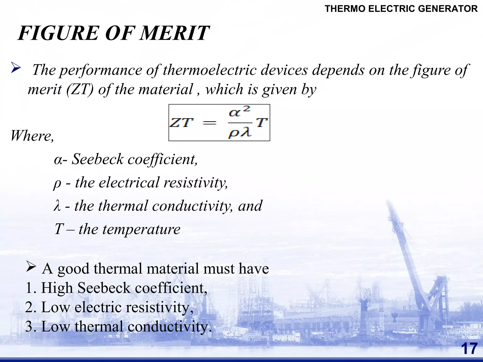
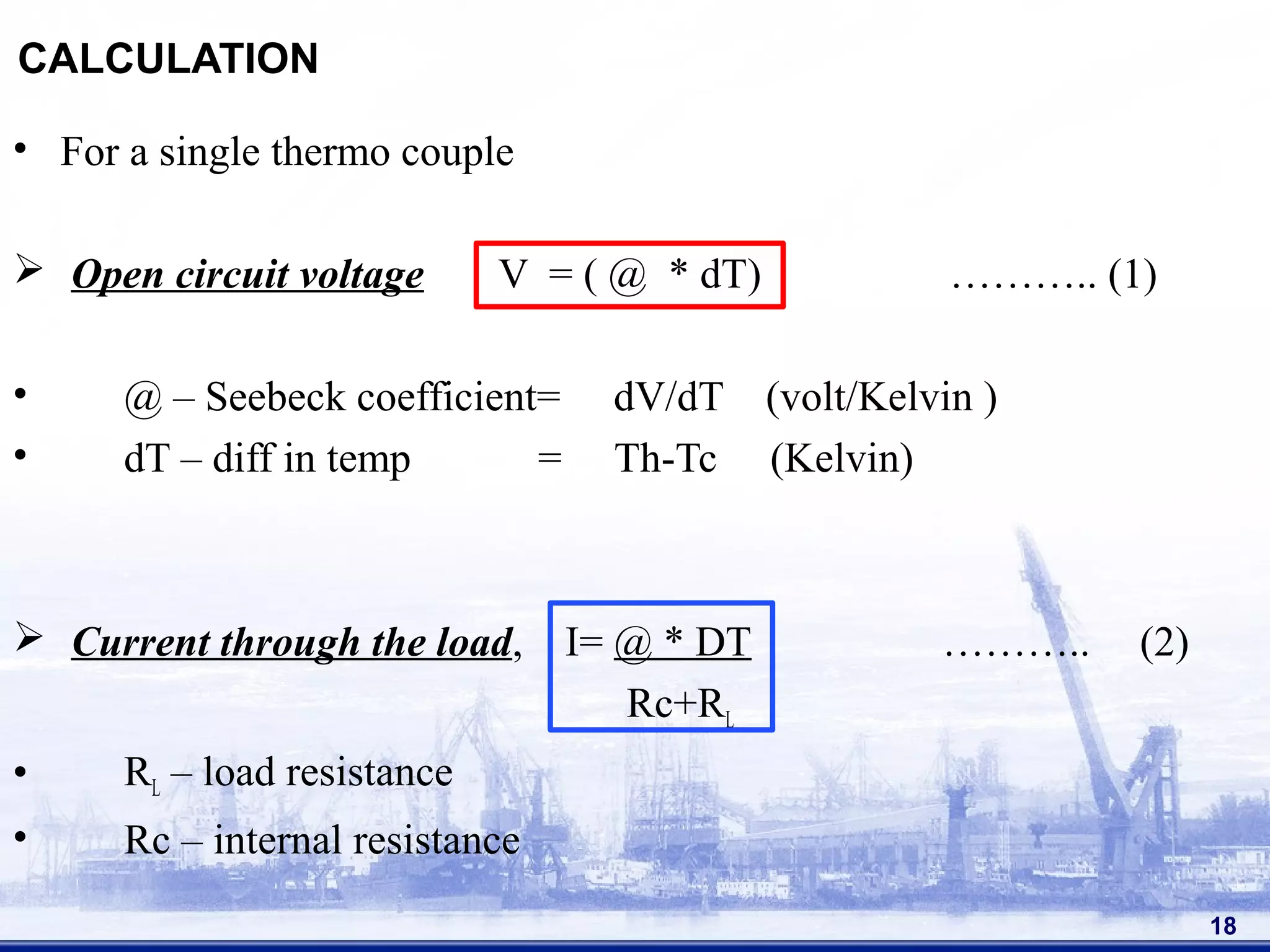
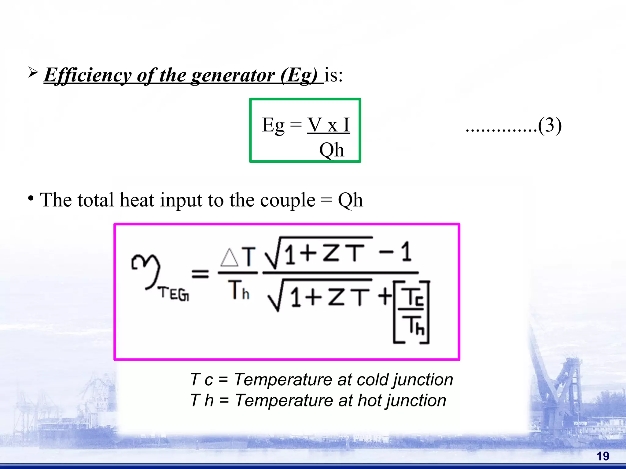
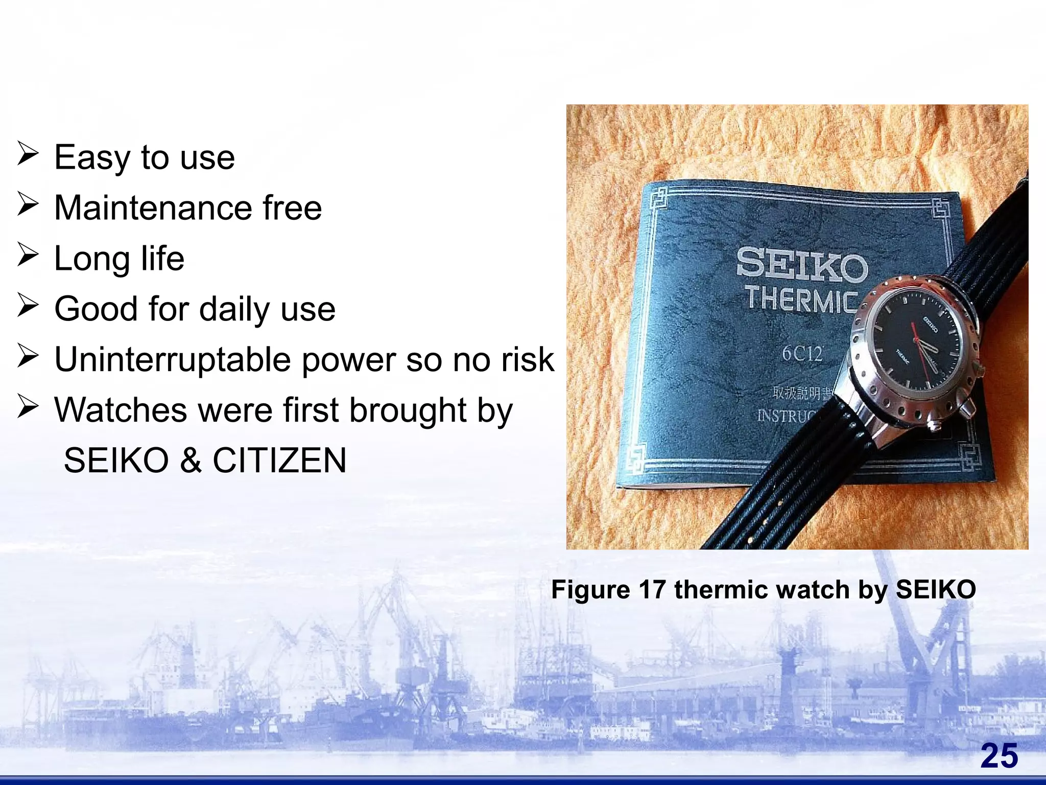
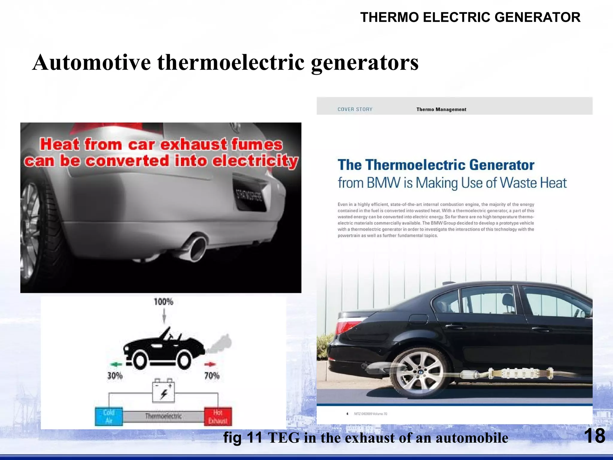
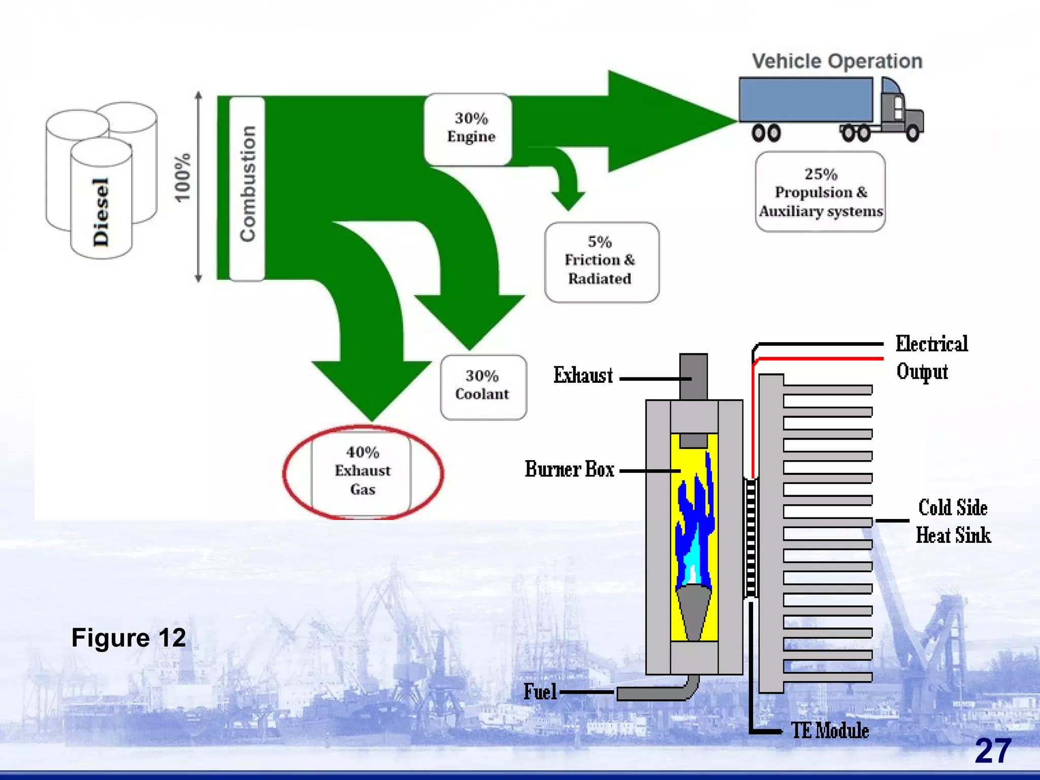
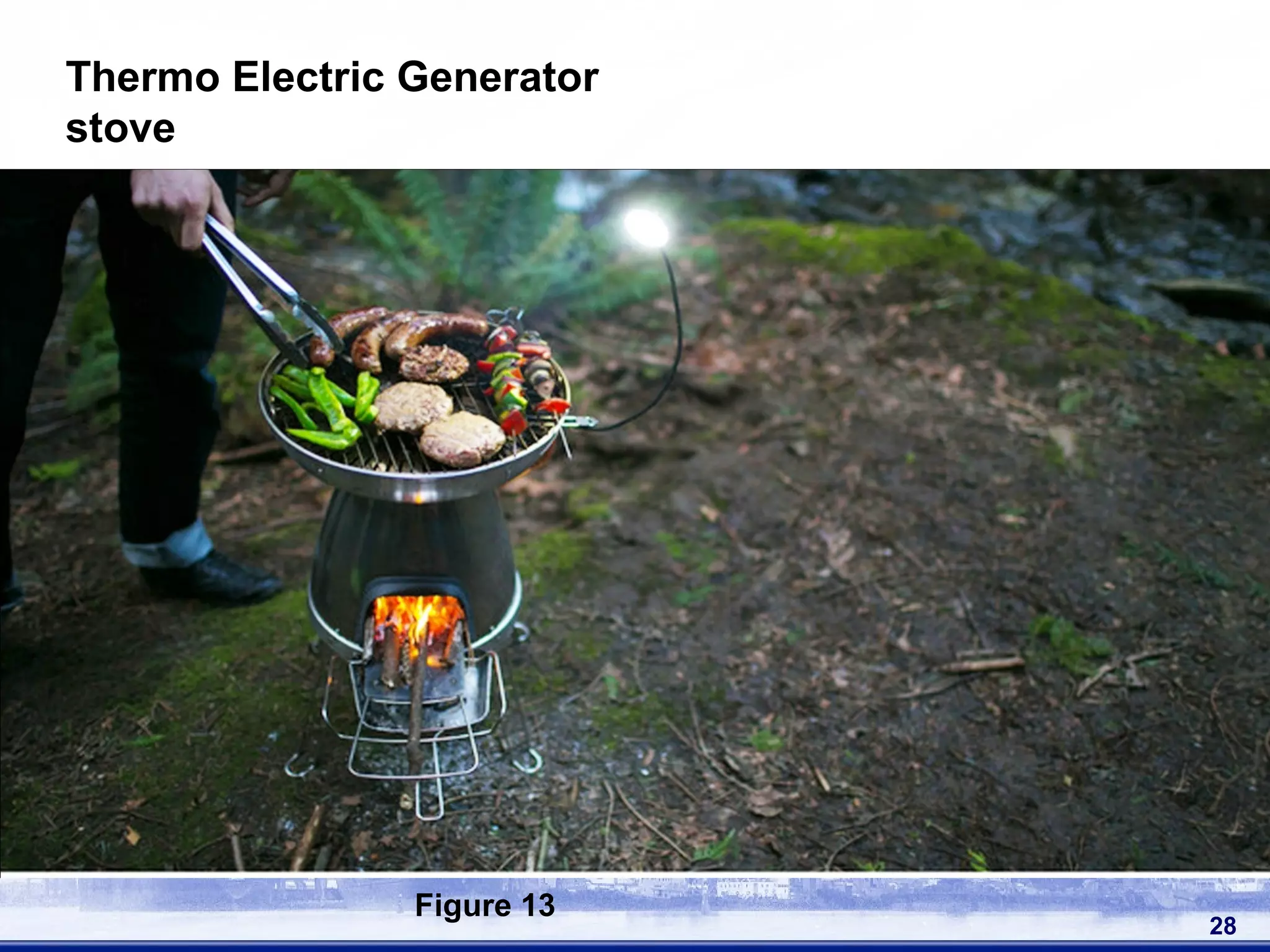
The document discusses thermoelectric generators (TEGs), which convert temperature differences directly into electrical power via the Seebeck effect. TEGs have various applications such as powering low-power electronics by harvesting waste heat from sources like the human body, car exhaust, and industrial machinery. While TEGs have advantages like solid-state operation and maintenance-free use, their efficiency is still relatively low compared to other power generation methods. Research continues on improving TEG materials and designs to increase their performance and viability.
![Thomas Johann Seebeck [ 1770 – 1831 ]
8
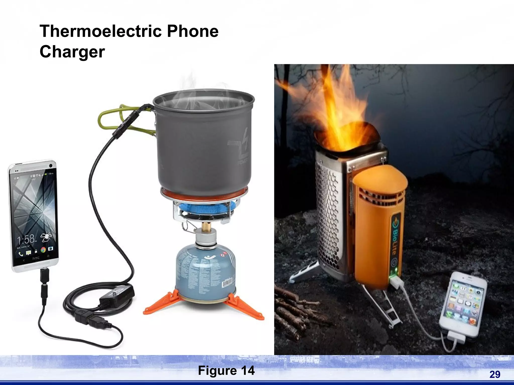
Figure 4](https://image.slidesharecdn.com/seminarppt-150404224537-conversion-gate01/75/THERMOELECTRIC-GENERATORS-SEMINAR-IEEE-8-2048.jpg)
![Jean Peltier [ 1785 - 1845 ]
12
Figure 7](https://image.slidesharecdn.com/seminarppt-150404224537-conversion-gate01/75/THERMOELECTRIC-GENERATORS-SEMINAR-IEEE-12-2048.jpg)


![Reference
[1] Joao Paulo Carmo,Luis Miguel Goncalves and Jose Higino Correia, “Thermoelectric microconverter
for energy harvesting systems”, IEEE transactions on industrial electronics, VOL. 57, NO. 3, march
2010
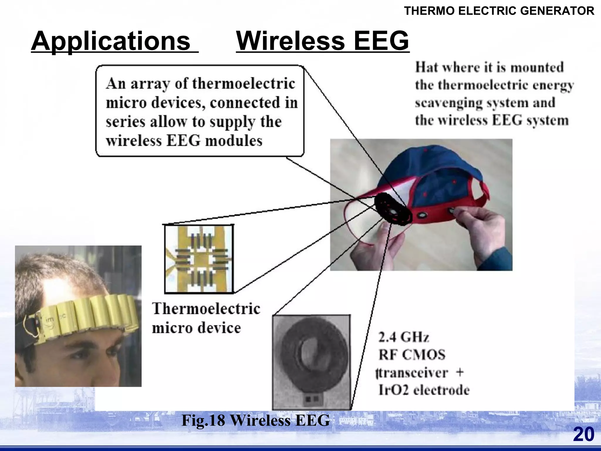
[2] Tom Torfs, Vladimir Leonov, Refet Firat Yazicioglu,Patrick Merken, Chris Van Hoof,” Wearable
Autonomous Wireless Electro-encephalography System Fully Powered by Human Body Heat”, IEEE
SENSORS 2008 Conference.
[3] L.M. Goncalves and J.G. Rocha,” Application of Microsystems Technology in the Fabrication of
Thermoelectric Micro-Converters”, Solid State Circuits Technologies, Book edited by: Jacobus W.
Swart.
[4] Tianqi Yang, Jinsheng Xiao, Wenyu Zhao, Qingjie Zhang,”Structural Optimization of Two-stage
Thermoelectric Generator for Wide Temperature Range Application”,2011 IEEE.
[5] Xiaodong Zhang, C.C. Chan, and Wenlong Li,” An Automotive Thermoelectric Energy System with
Parallel Configuration for Engine Waste Heat Recovery”, IEEE trasactions on industrial electronics
2010.
[6] Luciana Wasnievski da Silva,and Massoud Kaviany,” Fabrication and Measured Performance of a
First-Generation Microthermoelectric Cooler”, Journal of microelectro mechanical systems,VOL. 14,
NO. 5,october 2005.
[7] Design and Fabrication of Heat Storage Thermoelectric Harvesting Devices M. E. Kiziroglou,
Member, IEEE, S. W. Wright, T. T. Toh, P. D. Mitcheson, Senior Member, IEEE,Th. Becker and E.
M. Yeatman, Fellow, IEEE 2012
34
THERMO ELECTRIC GENERATOR](https://image.slidesharecdn.com/seminarppt-150404224537-conversion-gate01/75/THERMOELECTRIC-GENERATORS-SEMINAR-IEEE-34-2048.jpg)