Download as PDF, PPTX
![Temperature Scales:
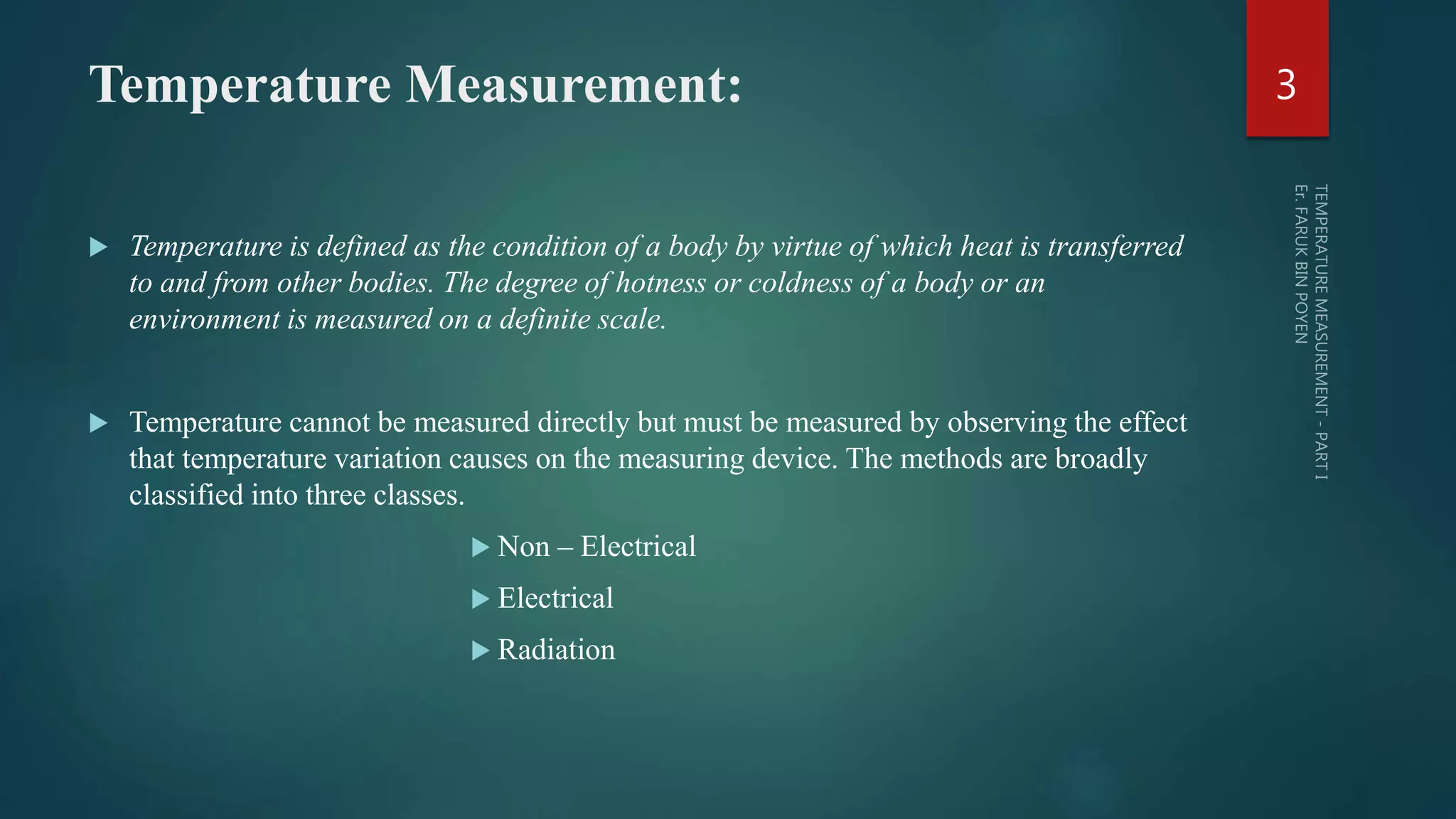
Absolute Temperature (Kelvin scale): K = °C + 273.15,
°C being temperature in Celsius scale.
Absolute Scale (Rankine scale): R = °F + 459.69,
°F being temperature in Fahrenheit scale.
[
𝑇2
𝑇1
] 𝑅𝑎𝑛𝑘𝑖𝑛𝑒= [
𝑇2
𝑇1
] 𝐾𝑒𝑙𝑣𝑖𝑛
℉ = 32 +
9
5
℃ ≡
℃
100
=
℉−32
180
R =
9
5
K
Reaumur Scale: R’ assigns 0° R’ to the ice – point and 80° R’ to the steam – point and often finds use in
alcohol industry.
Lower fixed point or ice – point is the temperature of ice prepared from distilled water at 760 mm of
mercury.
Upper fixed point or steam – point is the temperature of steam prepared from distilled water boiling at 760
mm of mercury.
4](https://image.slidesharecdn.com/temperaturemeasurement-parti-161103122445/75/Temperature-measurement-part-i-4-2048.jpg)
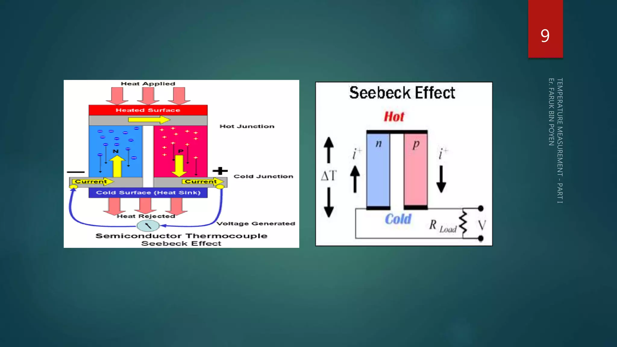
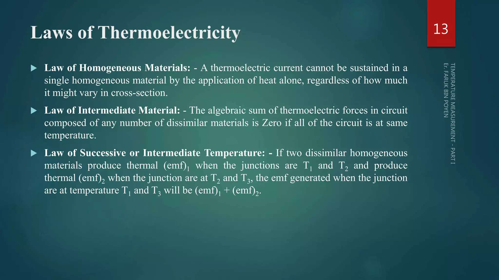
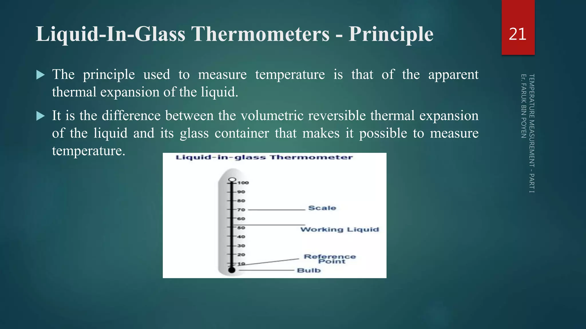

The document discusses various aspects of temperature measurement, including temperature scales, methods, and the principles of different thermometers such as bimetallic, liquid-in-glass, and gas-filled thermometers. It explains temperature definitions, the laws of thermoelectricity, and the relevance of effects like the Seebeck, Peltier, and Thomson effects in temperature measurement. Additionally, it highlights the advantages and disadvantages of various temperature measurement methods and instruments.