Downloaded 189 times


![References
[1] S.B. Riffat*, Xiaoli Ma ," Thermoelectrics: a review of present and
potential applications" , www.elsevier.com/locate/apthermeng.
[2] Mostafa Hasania and Nader Rahbar," Application of thermoelectric
cooler as a power generator in waste heat recovery from a PEM fuel cell-
An experimental study", www.elsevier.com/locate/he.
[3] Wei Hea, Gan Zhang,Xingxing Zhang, Jie Ji, Guiqiang Li and Xudong
Zhao," Recent development and application of thermoelectric generator
and cooler", www.elsevier.com/locate/apenergy .
[4] X.F. Zheng, C.X. Liu, Y.Y. Yann, Q. Wang, “A review of thermoelectrics
research–Recent developments and potentials for sustainable and
renewable energy applications” , www.elsevier.com/locate/rser .
[5] Francis Stabler, “Automotive Thermoelectric Generator Design Issues”
[6] P. Mohamed Shameer, D. Christopher, “Design of Exhaust Heat
Recovery Power Generation System Using Thermo-Electric Generator”
[7] http://www.nature.com](https://image.slidesharecdn.com/a98a3be4-5739-4ec4-ac98-aed12722025f-160809225432/85/Thermoelectric-Generation-29-320.jpg)


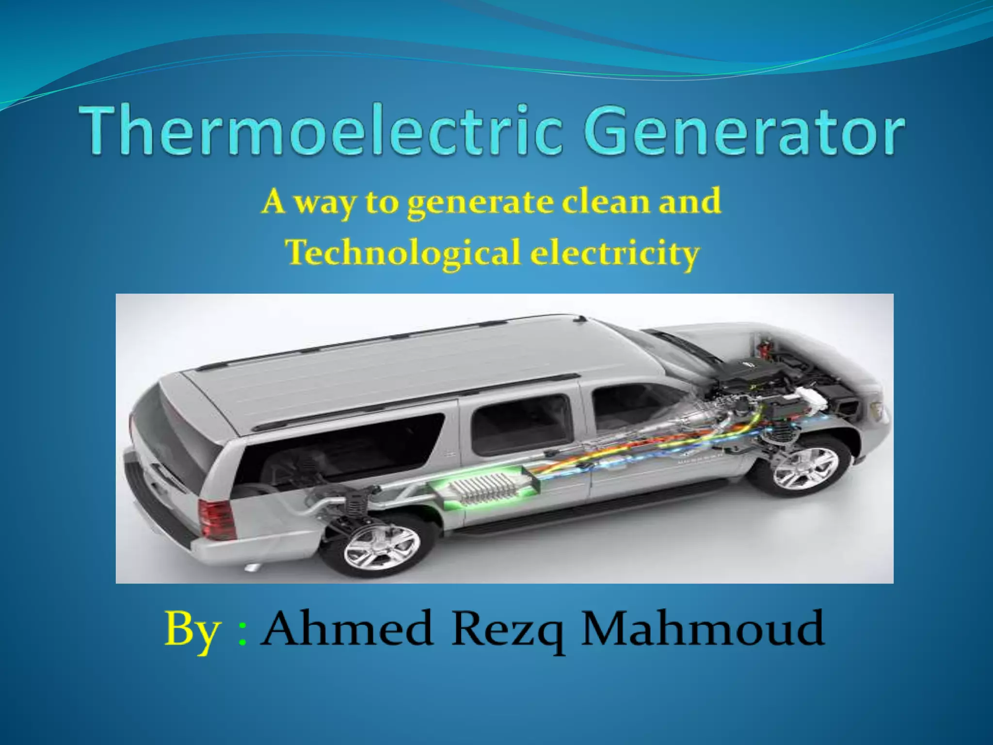
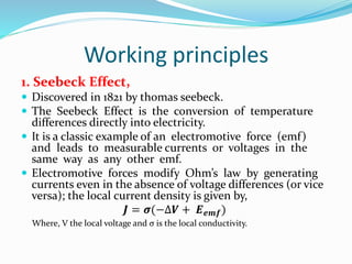
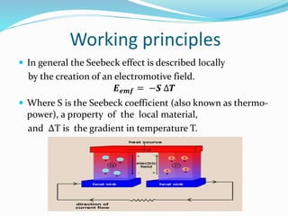
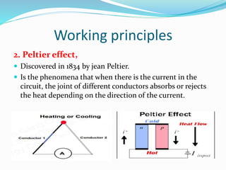
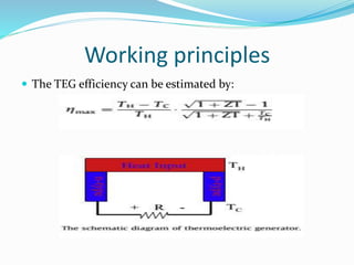
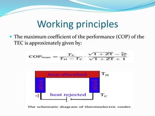
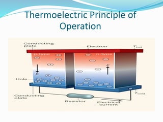
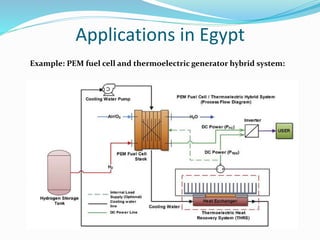
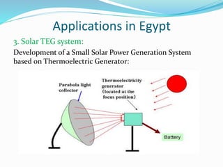
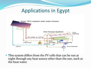
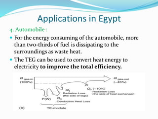
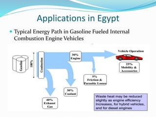
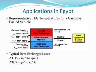
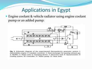
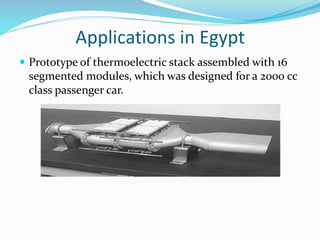
The document discusses thermoelectric generators and their working principles. Thermoelectric generators can directly convert temperature differences into electricity through the Seebeck effect and vice versa through the Peltier effect. They have applications in waste heat recovery from vehicles, industry, and solar power generation due to their solid-state operation without moving parts. However, their efficiency is still relatively low. The document also discusses thermoelectric materials and provides examples of applications of thermoelectric generators in Egypt.