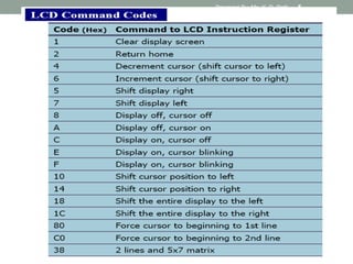
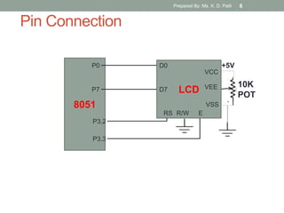
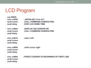
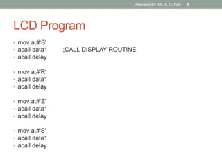
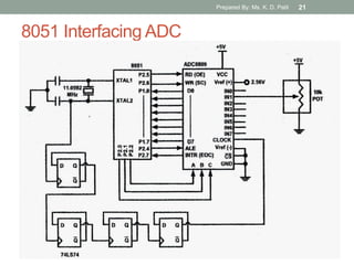
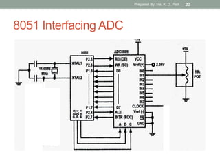
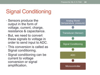
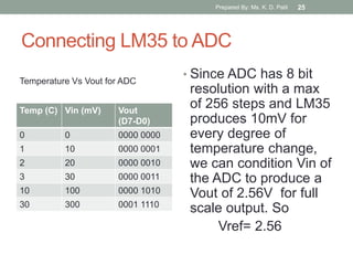
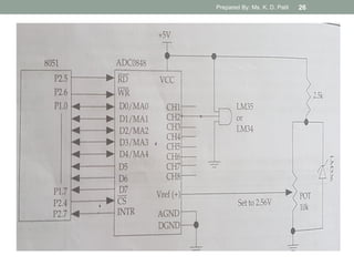
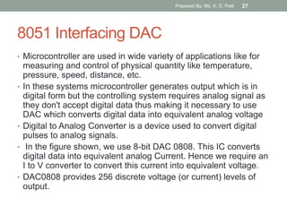
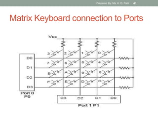
SlideShare a Scribd company logo
1 of 44
Download to read offline
8051 Interfacing & Applications
Subject : Processor Architecture & Interfacing
Class : SEIT
Prepared By
Ms. K. D. Patil, AP
Department of IT, Sanjivani COE, Kopargaon.
Prepared By: Ms. K. D. Patil 1
8255 PPI Pin
Diagram
Prepared By: Ms. K. D. Patil 2
8255 Block Diagram
Prepared By: Ms. K. D. Patil 3
8051 Interfacing LCD (Liquid Crystal
Display)
Prepared By: Ms. K. D. Patil 4
Prepared By: Ms. K. D. Patil 5
Pin Connection
8051
P0
P7 LCD
VCC
VEE
VSS
RS R/W E
D0
D7
P3.3
P3.2
10K
POT
+5V
Prepared By: Ms. K. D. Patil 6
LCD Program
• org 0000h
• mov a,#38h ; INITIALIZE 2 line 5x7
• acall comm ;CALL COMMAND SUBROUTINE
• acall delay ;GIVE LCD SOME TIME
• mov a,#0eh ;DISPLAY ON,CURSOR ON
• acall comm ;CALL COMMAND SUBROUTINE
• acall delay
• mov a,#01h ;clear LCD
• acall comm
• acall delay
• mov a,#06h ;shift cursor right
• acall comm
• acall delay
• mov a,#80h ;FORCE CURSOR TO BEGINNING OF FIRST LINE
• acall comm
• acall delay
Prepared By: Ms. K. D. Patil 7
LCD Program
• mov a,#„S'
• acall data1 ;CALL DISPLAY ROUTINE
• acall delay
• mov a,#'R'
• acall data1
• acall delay
• mov a,#„E'
• acall data1
• acall delay
• mov a,#'S'
• acall data1
• acall delay
Prepared By: Ms. K. D. Patil 8
LCD Program
• comm: ;SEND COMMAND TO LCD
• mov p0,a ;COPY REG A TO PORT0
• clr p2.2 ;RS=0 FOR COMMAND
• clr p2.1 ;R/W=0 FOR WRITE
• setb p2.0 ;E=1
• clr p2.0 ;E=0
ret
• data1: ;WRITE DATA TO LCD
• mov p0,a ;COPY REG A TO PORT0
• setb p2.2 ;RS=1 FOR DATA
• clr p2.1 ;R/W=0 FOR WRITE
• setb p2.0 ;E=1
• clr p2.0 ;E=0
ret
• delay: mov r1,#255
• here2: mov r2,#255
• here: djnz r2,here
• djnz r1,here2
• Ret
• end
Prepared By: Ms. K. D. Patil 9
8051 Interfacing LED
• LED (Light Emitting Diode) is a P N
junction diode which emits light when
activated.
• It is activated when the PN junction
sustains a forward voltage (forward bias), a
current from P to N, called forward current.
• When this current is applied, electrons
recombine with electron holes within the
device thereby releasing energy in form of
light.
• LED finds application in traffic signals,
lighting, camera flashes etc.
• The way to distinguish between the
positive and negative terminal is, the
positive is longer than the negative in
length.
Prepared By: Ms. K. D. Patil 10
8051 Interfacing LED
• While LEDs are interfaced
with 8051, Quartz crystals or
ceramic resonator that
determines the operating
frequency of 8051
microcontroller is needed.
• The XTAL1 and XTAL2 can
be configured in two ways;
• external clock drive configuration
• internal clock drive configuration.
• Two capacitors C1 and C2
are connected to the quartz
crystal. It can be a quartz
crystal or ceramic resonator.
• The crystal oscillator frequency is
from 1.2MHz to 12MHz. The crystal
oscillator is used to generate clock
pulses that provide the means for
timing calculation.
• Crystal pins are connected to the
ground through capacitors of 33pf.
Prepared By: Ms. K. D. Patil 11
8051 Interfacing LED
• In the following Diagram, LEDs are connected to the
port P0.
• LEDs need approximately voltage drop of 1.7V and
10mA current to flow through them in order to glow at
maximum intensity.
Prepared By: Ms. K. D. Patil 12
8051 Interfacing LED
Prepared By: Ms. K. D. Patil 13
8051 Interfacing 7 Segment Display
• 7 segment display is a 10 pin electronic component
with eight led’s embedded inside it to displays number
from 0 to 9 even we can display few characters like A,
B, C, H, E, e, F, etc. .
• It is available in two configurations:
• common cathode
• common anode
• In Common Anode to light up any given segment the
corresponding Cathode pin should be connected to
ground or reference ,which completes the circuit and
LED will be in forward bias.
• In Common Cathode to corresponding LED Anode pin
the circuit will be completed and the particular LED will
be light up since it will be in forward bias.
Prepared By: Ms. K. D. Patil 14
8051 Interfacing 7 Segment Display
• A seven segment display consists
of seven LEDs arranged in the
form of a “squarish eight”
slightly inclined to the right and a
single LED as the dot character.
Different characters can be
displayed by selectively glowing
the required LED segments.
Prepared By: Ms. K. D. Patil 15
8051 Interfacing 7 Segment Display
Prepared By: Ms. K. D. Patil 16
8051 Interfacing ADC
• Digital computers use binary
values but in physical world
everything is Analog
(continuous) eg. Temperature,
Pressure
• A physical quantity is converted
into electrical (voltage, current)
signals using a device called as
Transducer (also referred as
Sensors).
• We need Analog-to-Digital
converter (ADC) to translate
Analog signals to Digital number
so that Microcontroller can read
and process them.
• ADC0808 allows us to monitor
upto 8 different analog input
channels using single chip
Prepared By: Ms. K. D. Patil 17
ADC0808
Prepared By: Ms. K. D. Patil 18
Address Lines (A,B,C)
Selected ADC
channel
C B A
IN0 0 0 0
IN1 0 0 1
IN2 0 1 0
IN3 0 1 1
IN4 1 0 0
IN5 1 0 1
IN6 1 1 0
IN7 1 1 1
• ADC0808 has 8-bit
data output
• 8 analog input
channels are
multiplexed and
selected using three
address pins A, B & C.
Prepared By: Ms. K. D. Patil 19
Signals for A/D Conversion
• Address Latch Enable (ALE): A LOW-TO-HIGH signal at this
pin will latch the above-selected address and selected the
respective channel for ADC conversion.
• START Conversion (SC): The A/D converter‟s successive
approximation register (SAR) is reset on the positive edge of the
start conversion (SC) pulse. Thus we need to generate a LOW-
HIGH pulse for starting the ADC conversion.
• End of Conversion (EOC): Once the conversion is over, this
pin is pulled HIGH by ADC0808. This pin needs to be monitored
for the conversion to complete and then read the data.
• Output Enable(OE): ADC0808 does the A/D conversion and
holds the data in the internal registers. A HIGH signal on this pin
will bring the data on the output lines.
• D0-D7 are the digital Data output lines.
Prepared By: Ms. K. D. Patil 20
8051 Interfacing ADC
Prepared By: Ms. K. D. Patil 21
8051 Interfacing ADC
Prepared By: Ms. K. D. Patil 22
8051 Interfacing Temperature Sensor
(LM34/LM35)
• Temperature is converted to electrical signals using a
transducer called as Thermistor.
• Simple and widely used Temperature sensors include
LM34 & LM35 from Semiconductor Corp
• LM34 does not require external calibration since it is
internally calibrated.
• LM35 are precision integrated circuit temperature sensors
whose output voltage is linearly proportional to Celsius
temp. It does not require external calibration since it is
internally calibrated. It outputs 10mV for each degree of
centigrade temperature.
Prepared By: Ms. K. D. Patil 23
Signal Conditioning
• Sensors produce the
output in the form of
voltage, current, charge,
resistance & capacitance.
• But, we need to convert
these signals to voltage in
order to send input to ADC.
• This conversion is called as
Signal conditioning.
• Signal conditioning can be
current to voltage
conversion or signal
amplification.
Analog World
(temperature, pressure)
Transducer (Sensor)
Signal Conditioning
ADC
Microcontroller
Prepared By: Ms. K. D. Patil 24
Connecting LM35 to ADC
Temp (C) Vin (mV) Vout
(D7-D0)
0 0 0000 0000
1 10 0000 0001
2 20 0000 0010
3 30 0000 0011
10 100 0000 1010
30 300 0001 1110
• Since ADC has 8 bit
resolution with a max
of 256 steps and LM35
produces 10mV for
every degree of
temperature change,
we can condition Vin of
the ADC to produce a
Vout of 2.56V for full
scale output. So
Vref= 2.56
Temperature Vs Vout for ADC
Prepared By: Ms. K. D. Patil 25
Interfacing Diagram
Prepared By: Ms. K. D. Patil 26
8051 Interfacing DAC
• Microcontroller are used in wide variety of applications like for
measuring and control of physical quantity like temperature,
pressure, speed, distance, etc.
• In these systems microcontroller generates output which is in
digital form but the controlling system requires analog signal as
they don't accept digital data thus making it necessary to use
DAC which converts digital data into equivalent analog voltage
• Digital to Analog Converter is a device used to convert digital
pulses to analog signals.
• In the figure shown, we use 8-bit DAC 0808. This IC converts
digital data into equivalent analog Current. Hence we require an
I to V converter to convert this current into equivalent voltage.
• DAC0808 provides 256 discrete voltage (or current) levels of
output.
Prepared By: Ms. K. D. Patil 27
DAC0808
• In the MC1408 (DAC0808), the digital inputs are converted
to current (Iout), and by connecting a resistor to the Iout pin,
we convert the result to voltage.
• The total current provided by the Iout pin is a function of the
binary numbers at the D0 – D7 inputs of the DAC0808 and
the reference current (Iref), and is as follows:
• where D0 is the LSB, D7 is the MSB for the inputs, and Iref
is the input current that must be applied to pin 14. The Iref
current is generally set to 2.0 mA.
Prepared By: Ms. K. D. Patil 28
Prepared By: Ms. K. D. Patil 29
Interfacing Diagram
Prepared By: Ms. K. D. Patil 30
8051 Interfacing Stepper Motor
 Stepper motor is a widely
used device that
translates electrical pulses
into mechanical
movement
 Stepper motor is used in
applications for position
control such as
 disk drives
 dot matrix printer
 robotics etc.
 Stepper motors commonly
have a permanent magnet
rotor (shaft) surrounded
by a stator
Prepared By: Ms. K. D. Patil 31
• Commonly used stepper
motors have four stator
windings that are paired
with a center – tapped
common. Such motors are
called as four-phase or
unipolar stepper motor.
• It has a permanent magnet
rotor (shaft) which is
surrounded by a stator.
• A practical PM stepper
motor will have 1.8 degrees
step angle and 50 tooth on
its rotor.
• There are 8 main poles on
the stator, each having 5
tooth in the pole face
Prepared By: Ms. K. D. Patil 32
Prepared By: Ms. K. D. Patil 33
Prepared By: Ms. K. D. Patil 34
Prepared By: Ms. K. D. Patil 35
Prepared By: Ms. K. D. Patil 36
4 step Sequence
Step Windi
ng A
Windi
ng B
Windi
ng C
Windi
ng D
1 1 0 0 1
2 1 1 0 0
3 0 1 1 0
4 0 0 1 1
Prepared By: Ms. K. D. Patil 37
Step Angle
• Step angle is defined as the minimum degree of rotation
associated with a single step.
• Total number of steps needed to rotate 360 degrees is
Steps per Revolution.
No of steps per revolution = 360° / step angle
• Steps per second = (rpm x steps per revolution) / 60
• Example: step angle = 2°
No of steps per revolution = 180
Prepared By: Ms. K. D. Patil 38
Interfacing Diagram
Prepared By: Ms. K. D. Patil 39
8051 Interfacing Keyboard
• Keyboards are organized in a matrix of rows and columns.
• The CPU processes both rows and columns through ports
• So, with two 8-bit ports, an 8X8 matrix of keys can be
connected to the controller.
• When a key is pressed, a row and a column make a
contact. Otherwise there is no connection
• In microcontroller, programs stored in EPROM scan the
keys continuously.
• In the following figure, 4 X 4 matrix connected to two ports.
rows are connected to output ports and columns are
connected to an input port.
Prepared By: Ms. K. D. Patil 40
Matrix Keyboard connection to Ports
Prepared By: Ms. K. D. Patil 41
Scanning & Identifying Key
• It is a function of microcontroller to scan the keyboard
continuously to detect and identify key pressed
• To detect Pressed key microcontroller grounds all rows by
providing 0 to output latch, then it reads the columns
• If the data read from columns is D3-D0 = 1111 , no key is pressed
and the process continues till key press is detected.
• If one of the column bits has a zero, means key press has
occurred.
• If D3-D0 = 1101 this means that key in the column D1 has been
pressed.
• After detecting a key press, microcontroller will go through the process
of identifying key.
Prepared By: Ms. K. D. Patil 42
Scanning & Identifying Key
• Starting with the top Row, the microcontroller grounds it by
providing a low to Row D0 only
• If reads a column if data read is all 1s, no key in that row is
activated and the process is moved to the next row.
• It grounds the next row, reads the columns, and checks for
any zero
• This process continues until row is identified
• After identification of the Row in which Key has been
pressed, find out column the key press belongs to
Prepared By: Ms. K. D. Patil 43
References:
• M. A. Mazidi, J. C. Mazidi, R. D. McKinlay, “The 8051
Microcontroller & Embedded Systems using Assembly and
C”, 2nd Edition, Pearson publication
Prepared By: Ms. K. D. Patil 44

More Related Content

What's hot

Keypad Interfacing with 8051 Microcontroller
Keypad Interfacing with 8051 MicrocontrollerKeypad Interfacing with 8051 Microcontroller
Keypad Interfacing with 8051 MicrocontrollerSudhanshu Janwadkar
 
Addressing modes of 8051
Addressing modes of 8051Addressing modes of 8051
Addressing modes of 8051SARITHA REDDY
 
DAC Interfacing with 8051.pdf
DAC Interfacing with 8051.pdfDAC Interfacing with 8051.pdf
DAC Interfacing with 8051.pdfSrikrishna Thota
 
Microcontroller-8051.ppt
Microcontroller-8051.pptMicrocontroller-8051.ppt
Microcontroller-8051.pptDr.YNM
 
8051 microcontroller
8051 microcontroller 8051 microcontroller
8051 microcontroller Gaurav Verma
 
8051 Microcontroller PPT's By Er. Swapnil Kaware
8051 Microcontroller PPT's By Er. Swapnil Kaware8051 Microcontroller PPT's By Er. Swapnil Kaware
8051 Microcontroller PPT's By Er. Swapnil KawareProf. Swapnil V. Kaware
 
Timer And Counter in 8051 Microcontroller
Timer And Counter in 8051 MicrocontrollerTimer And Counter in 8051 Microcontroller
Timer And Counter in 8051 MicrocontrollerJay Makwana
 
8051 Addressing Modes
8051 Addressing Modes8051 Addressing Modes
8051 Addressing ModesSenthil Kumar
 
Memory & I/O interfacing
Memory & I/O  interfacingMemory & I/O  interfacing
Memory & I/O interfacingdeval patel
 
8086 pin details
8086 pin details8086 pin details
8086 pin detailsAJAL A J
 
8085 interrupts
8085 interrupts8085 interrupts
8085 interruptsRam Babu
 
Microcontroller 8051 and its interfacing
Microcontroller 8051 and its interfacingMicrocontroller 8051 and its interfacing
Microcontroller 8051 and its interfacingAnkur Mahajan
 
Interfacing stepper motor
Interfacing stepper motorInterfacing stepper motor
Interfacing stepper motorPRADEEP
 

What's hot (20)

Keypad Interfacing with 8051 Microcontroller
Keypad Interfacing with 8051 MicrocontrollerKeypad Interfacing with 8051 Microcontroller
Keypad Interfacing with 8051 Microcontroller
 
Addressing modes of 8051
Addressing modes of 8051Addressing modes of 8051
Addressing modes of 8051
 
DAC Interfacing with 8051.pdf
DAC Interfacing with 8051.pdfDAC Interfacing with 8051.pdf
DAC Interfacing with 8051.pdf
 
8255 PPI
8255 PPI8255 PPI
8255 PPI
 
Microcontroller-8051.ppt
Microcontroller-8051.pptMicrocontroller-8051.ppt
Microcontroller-8051.ppt
 
Interrupts in 8051
Interrupts in 8051Interrupts in 8051
Interrupts in 8051
 
8051 microcontroller
8051 microcontroller 8051 microcontroller
8051 microcontroller
 
Interrupts of microprocessor 8085
Interrupts of microprocessor  8085Interrupts of microprocessor  8085
Interrupts of microprocessor 8085
 
8051 Microcontroller PPT's By Er. Swapnil Kaware
8051 Microcontroller PPT's By Er. Swapnil Kaware8051 Microcontroller PPT's By Er. Swapnil Kaware
8051 Microcontroller PPT's By Er. Swapnil Kaware
 
Timer And Counter in 8051 Microcontroller
Timer And Counter in 8051 MicrocontrollerTimer And Counter in 8051 Microcontroller
Timer And Counter in 8051 Microcontroller
 
8051 Addressing Modes
8051 Addressing Modes8051 Addressing Modes
8051 Addressing Modes
 
Pin diagram 8085
Pin diagram 8085 Pin diagram 8085
Pin diagram 8085
 
Timing diagram 8085 microprocessor
Timing diagram 8085 microprocessorTiming diagram 8085 microprocessor
Timing diagram 8085 microprocessor
 
Microprocessor 8086
Microprocessor 8086Microprocessor 8086
Microprocessor 8086
 
Memory & I/O interfacing
Memory & I/O  interfacingMemory & I/O  interfacing
Memory & I/O interfacing
 
8086 pin details
8086 pin details8086 pin details
8086 pin details
 
8085 interrupts
8085 interrupts8085 interrupts
8085 interrupts
 
Microcontroller 8051 and its interfacing
Microcontroller 8051 and its interfacingMicrocontroller 8051 and its interfacing
Microcontroller 8051 and its interfacing
 
8155 PPI
8155 PPI8155 PPI
8155 PPI
 
Interfacing stepper motor
Interfacing stepper motorInterfacing stepper motor
Interfacing stepper motor
 

Similar to 8051 interfacing

Unit iv microcontrollers final
Unit iv microcontrollers finalUnit iv microcontrollers final
Unit iv microcontrollers finalSARITHA REDDY
 
adcanddac hai kya bhayy me know if-01.pptx
adcanddac hai kya bhayy me know if-01.pptxadcanddac hai kya bhayy me know if-01.pptx
adcanddac hai kya bhayy me know if-01.pptxshivraj3252
 
Mc module5 lcd_interface_ppt_msj
Mc module5 lcd_interface_ppt_msjMc module5 lcd_interface_ppt_msj
Mc module5 lcd_interface_ppt_msjmangala jolad
 
Interfacing with peripherals: analog to digital converters and digital to ana...
Interfacing with peripherals: analog to digital converters and digital to ana...Interfacing with peripherals: analog to digital converters and digital to ana...
Interfacing with peripherals: analog to digital converters and digital to ana...NimeshSingh27
 
digitalvoltmeterusing805112b2-170214173216 (1).pdf
digitalvoltmeterusing805112b2-170214173216 (1).pdfdigitalvoltmeterusing805112b2-170214173216 (1).pdf
digitalvoltmeterusing805112b2-170214173216 (1).pdfsatyamsinha37
 
DIGITAL VOLTMETER USING 8051 MICROCONTROLLER
DIGITAL VOLTMETER USING 8051 MICROCONTROLLERDIGITAL VOLTMETER USING 8051 MICROCONTROLLER
DIGITAL VOLTMETER USING 8051 MICROCONTROLLERChirag Lakhani
 
project - Copy
project - Copyproject - Copy
project - Copypiedaholic
 
Analog to Digital Converters
Analog to Digital ConvertersAnalog to Digital Converters
Analog to Digital ConvertersAmitabh Shukla
 
Digital voltmeter using 89c51 microcontroller
Digital voltmeter using 89c51 microcontrollerDigital voltmeter using 89c51 microcontroller
Digital voltmeter using 89c51 microcontrollerSaylee joshi
 
analog to digital converter and dac final
analog to digital converter and dac finalanalog to digital converter and dac final
analog to digital converter and dac finalDrVikasMahor
 
Construction of digital voltmeter by Bapi Kumar Das
Construction of digital voltmeter by Bapi Kumar DasConstruction of digital voltmeter by Bapi Kumar Das
Construction of digital voltmeter by Bapi Kumar DasB.k. Das
 
Pic ppt 13104022(4th_year)
Pic ppt 13104022(4th_year)Pic ppt 13104022(4th_year)
Pic ppt 13104022(4th_year)Daman Singh
 
Digital clock workshop
Digital clock workshopDigital clock workshop
Digital clock workshopKedarv
 
Distance Protection
Distance ProtectionDistance Protection
Distance Protectionncct
 
ADC and DAC interfacing.pdf
ADC and DAC interfacing.pdfADC and DAC interfacing.pdf
ADC and DAC interfacing.pdfVikasMahor3
 
Temperature Based Fan Controller
Temperature Based Fan Controller Temperature Based Fan Controller
Temperature Based Fan Controller richa1910n
 
MPC of TWT based Transmitter
MPC of TWT based TransmitterMPC of TWT based Transmitter
MPC of TWT based TransmitterAbhishek Sutrave
 
MICROPROCESSOR BASED SUN TRACKING SOLAR PANEL SYSTEM TO MAXIMIZE ENERGY GENER...
MICROPROCESSOR BASED SUN TRACKING SOLAR PANEL SYSTEM TO MAXIMIZE ENERGY GENER...MICROPROCESSOR BASED SUN TRACKING SOLAR PANEL SYSTEM TO MAXIMIZE ENERGY GENER...
MICROPROCESSOR BASED SUN TRACKING SOLAR PANEL SYSTEM TO MAXIMIZE ENERGY GENER...moiz89
 
interfacing of temperature sensor LM 35 with 8051.pdf
interfacing of temperature sensor LM 35 with 8051.pdfinterfacing of temperature sensor LM 35 with 8051.pdf
interfacing of temperature sensor LM 35 with 8051.pdfSrikrishna Thota
 

Similar to 8051 interfacing (20)

Unit iv microcontrollers final
Unit iv microcontrollers finalUnit iv microcontrollers final
Unit iv microcontrollers final
 
adcanddac hai kya bhayy me know if-01.pptx
adcanddac hai kya bhayy me know if-01.pptxadcanddac hai kya bhayy me know if-01.pptx
adcanddac hai kya bhayy me know if-01.pptx
 
Mc module5 lcd_interface_ppt_msj
Mc module5 lcd_interface_ppt_msjMc module5 lcd_interface_ppt_msj
Mc module5 lcd_interface_ppt_msj
 
Interfacing with peripherals: analog to digital converters and digital to ana...
Interfacing with peripherals: analog to digital converters and digital to ana...Interfacing with peripherals: analog to digital converters and digital to ana...
Interfacing with peripherals: analog to digital converters and digital to ana...
 
digitalvoltmeterusing805112b2-170214173216 (1).pdf
digitalvoltmeterusing805112b2-170214173216 (1).pdfdigitalvoltmeterusing805112b2-170214173216 (1).pdf
digitalvoltmeterusing805112b2-170214173216 (1).pdf
 
DIGITAL VOLTMETER USING 8051 MICROCONTROLLER
DIGITAL VOLTMETER USING 8051 MICROCONTROLLERDIGITAL VOLTMETER USING 8051 MICROCONTROLLER
DIGITAL VOLTMETER USING 8051 MICROCONTROLLER
 
project - Copy
project - Copyproject - Copy
project - Copy
 
Analog to Digital Converters
Analog to Digital ConvertersAnalog to Digital Converters
Analog to Digital Converters
 
Digital voltmeter using 89c51 microcontroller
Digital voltmeter using 89c51 microcontrollerDigital voltmeter using 89c51 microcontroller
Digital voltmeter using 89c51 microcontroller
 
analog to digital converter and dac final
analog to digital converter and dac finalanalog to digital converter and dac final
analog to digital converter and dac final
 
Construction of digital voltmeter by Bapi Kumar Das
Construction of digital voltmeter by Bapi Kumar DasConstruction of digital voltmeter by Bapi Kumar Das
Construction of digital voltmeter by Bapi Kumar Das
 
Pic ppt 13104022(4th_year)
Pic ppt 13104022(4th_year)Pic ppt 13104022(4th_year)
Pic ppt 13104022(4th_year)
 
Digital clock workshop
Digital clock workshopDigital clock workshop
Digital clock workshop
 
Distance Protection
Distance ProtectionDistance Protection
Distance Protection
 
ADC and DAC interfacing.pdf
ADC and DAC interfacing.pdfADC and DAC interfacing.pdf
ADC and DAC interfacing.pdf
 
Temperature Based Fan Controller
Temperature Based Fan Controller Temperature Based Fan Controller
Temperature Based Fan Controller
 
MPC of TWT based Transmitter
MPC of TWT based TransmitterMPC of TWT based Transmitter
MPC of TWT based Transmitter
 
A Commercial Low Cost, Highly Efficient UC3842 based High Brightness LED (HBL...
A Commercial Low Cost, Highly Efficient UC3842 based High Brightness LED (HBL...A Commercial Low Cost, Highly Efficient UC3842 based High Brightness LED (HBL...
A Commercial Low Cost, Highly Efficient UC3842 based High Brightness LED (HBL...
 
MICROPROCESSOR BASED SUN TRACKING SOLAR PANEL SYSTEM TO MAXIMIZE ENERGY GENER...
MICROPROCESSOR BASED SUN TRACKING SOLAR PANEL SYSTEM TO MAXIMIZE ENERGY GENER...MICROPROCESSOR BASED SUN TRACKING SOLAR PANEL SYSTEM TO MAXIMIZE ENERGY GENER...
MICROPROCESSOR BASED SUN TRACKING SOLAR PANEL SYSTEM TO MAXIMIZE ENERGY GENER...
 
interfacing of temperature sensor LM 35 with 8051.pdf
interfacing of temperature sensor LM 35 with 8051.pdfinterfacing of temperature sensor LM 35 with 8051.pdf
interfacing of temperature sensor LM 35 with 8051.pdf
 

More from KanchanPatil34

Unit 2_2 Binary Tree as ADT_General Tree.pdf
Unit 2_2 Binary Tree as ADT_General Tree.pdfUnit 2_2 Binary Tree as ADT_General Tree.pdf
Unit 2_2 Binary Tree as ADT_General Tree.pdfKanchanPatil34
 
Unit 2_3 Binary Tree Traversals.pdf
Unit 2_3 Binary Tree Traversals.pdfUnit 2_3 Binary Tree Traversals.pdf
Unit 2_3 Binary Tree Traversals.pdfKanchanPatil34
 
Unit 1_SLL and DLL.pdf
Unit 1_SLL and DLL.pdfUnit 1_SLL and DLL.pdf
Unit 1_SLL and DLL.pdfKanchanPatil34
 
Unit 1_Stack and Queue using Linked Organization.pdf
Unit 1_Stack and Queue using Linked Organization.pdfUnit 1_Stack and Queue using Linked Organization.pdf
Unit 1_Stack and Queue using Linked Organization.pdfKanchanPatil34
 
PAI Unit 3 Paging in 80386 Microporcessor
PAI Unit 3 Paging in 80386 MicroporcessorPAI Unit 3 Paging in 80386 Microporcessor
PAI Unit 3 Paging in 80386 MicroporcessorKanchanPatil34
 
PAI Unit 3 Multitasking in 80386
PAI Unit 3 Multitasking in 80386PAI Unit 3 Multitasking in 80386
PAI Unit 3 Multitasking in 80386KanchanPatil34
 
PAI Unit 2 Segmentation in 80386 microprocessor
PAI Unit 2 Segmentation in 80386 microprocessorPAI Unit 2 Segmentation in 80386 microprocessor
PAI Unit 2 Segmentation in 80386 microprocessorKanchanPatil34
 
PAI Unit 2 Protection in 80386 segmentation
PAI Unit 2 Protection in 80386 segmentationPAI Unit 2 Protection in 80386 segmentation
PAI Unit 2 Protection in 80386 segmentationKanchanPatil34
 
SE PAI Unit 2_Data Structures in 80386 segmentation
SE PAI Unit 2_Data Structures in 80386 segmentationSE PAI Unit 2_Data Structures in 80386 segmentation
SE PAI Unit 2_Data Structures in 80386 segmentationKanchanPatil34
 
SE PAI Unit 5_Timer Programming in 8051 microcontroller_Part 1
SE PAI Unit 5_Timer Programming in 8051 microcontroller_Part 1SE PAI Unit 5_Timer Programming in 8051 microcontroller_Part 1
SE PAI Unit 5_Timer Programming in 8051 microcontroller_Part 1KanchanPatil34
 
SE PAI Unit 5_Timer Programming in 8051 microcontroller_Part 2
SE PAI Unit 5_Timer Programming in 8051 microcontroller_Part 2SE PAI Unit 5_Timer Programming in 8051 microcontroller_Part 2
SE PAI Unit 5_Timer Programming in 8051 microcontroller_Part 2KanchanPatil34
 
SE PAI Unit 5_Serial Port Programming in 8051 micro controller_Part 3
SE PAI Unit 5_Serial Port Programming in 8051 micro controller_Part 3SE PAI Unit 5_Serial Port Programming in 8051 micro controller_Part 3
SE PAI Unit 5_Serial Port Programming in 8051 micro controller_Part 3KanchanPatil34
 
SE PAI Unit 5_Serial Port Programming in 8051 microcontroller_Part 2
SE PAI Unit 5_Serial Port Programming in 8051 microcontroller_Part 2SE PAI Unit 5_Serial Port Programming in 8051 microcontroller_Part 2
SE PAI Unit 5_Serial Port Programming in 8051 microcontroller_Part 2KanchanPatil34
 
SE PAI Unit 5_Serial Port Programming in 8051 microcontroller_Part 1
SE PAI Unit 5_Serial Port Programming in 8051 microcontroller_Part 1SE PAI Unit 5_Serial Port Programming in 8051 microcontroller_Part 1
SE PAI Unit 5_Serial Port Programming in 8051 microcontroller_Part 1KanchanPatil34
 
SE PAI Unit 5_IO programming in 8051
SE PAI Unit 5_IO programming in 8051SE PAI Unit 5_IO programming in 8051
SE PAI Unit 5_IO programming in 8051KanchanPatil34
 
Unit 5_Interrupt programming in 8051 micro controller - part 2
Unit 5_Interrupt programming in 8051 micro controller - part 2Unit 5_Interrupt programming in 8051 micro controller - part 2
Unit 5_Interrupt programming in 8051 micro controller - part 2KanchanPatil34
 
Unit 5_interrupt programming_Part 1
Unit 5_interrupt programming_Part 1Unit 5_interrupt programming_Part 1
Unit 5_interrupt programming_Part 1KanchanPatil34
 
Unit 3 se pai_ivt and idt
Unit 3 se pai_ivt and idtUnit 3 se pai_ivt and idt
Unit 3 se pai_ivt and idtKanchanPatil34
 
Unit 2 se pai_registers in 80386
Unit 2 se pai_registers in 80386Unit 2 se pai_registers in 80386
Unit 2 se pai_registers in 80386KanchanPatil34
 

More from KanchanPatil34 (20)

Unit 2_2 Binary Tree as ADT_General Tree.pdf
Unit 2_2 Binary Tree as ADT_General Tree.pdfUnit 2_2 Binary Tree as ADT_General Tree.pdf
Unit 2_2 Binary Tree as ADT_General Tree.pdf
 
Unit 2_1 Tree.pdf
Unit 2_1 Tree.pdfUnit 2_1 Tree.pdf
Unit 2_1 Tree.pdf
 
Unit 2_3 Binary Tree Traversals.pdf
Unit 2_3 Binary Tree Traversals.pdfUnit 2_3 Binary Tree Traversals.pdf
Unit 2_3 Binary Tree Traversals.pdf
 
Unit 1_SLL and DLL.pdf
Unit 1_SLL and DLL.pdfUnit 1_SLL and DLL.pdf
Unit 1_SLL and DLL.pdf
 
Unit 1_Stack and Queue using Linked Organization.pdf
Unit 1_Stack and Queue using Linked Organization.pdfUnit 1_Stack and Queue using Linked Organization.pdf
Unit 1_Stack and Queue using Linked Organization.pdf
 
PAI Unit 3 Paging in 80386 Microporcessor
PAI Unit 3 Paging in 80386 MicroporcessorPAI Unit 3 Paging in 80386 Microporcessor
PAI Unit 3 Paging in 80386 Microporcessor
 
PAI Unit 3 Multitasking in 80386
PAI Unit 3 Multitasking in 80386PAI Unit 3 Multitasking in 80386
PAI Unit 3 Multitasking in 80386
 
PAI Unit 2 Segmentation in 80386 microprocessor
PAI Unit 2 Segmentation in 80386 microprocessorPAI Unit 2 Segmentation in 80386 microprocessor
PAI Unit 2 Segmentation in 80386 microprocessor
 
PAI Unit 2 Protection in 80386 segmentation
PAI Unit 2 Protection in 80386 segmentationPAI Unit 2 Protection in 80386 segmentation
PAI Unit 2 Protection in 80386 segmentation
 
SE PAI Unit 2_Data Structures in 80386 segmentation
SE PAI Unit 2_Data Structures in 80386 segmentationSE PAI Unit 2_Data Structures in 80386 segmentation
SE PAI Unit 2_Data Structures in 80386 segmentation
 
SE PAI Unit 5_Timer Programming in 8051 microcontroller_Part 1
SE PAI Unit 5_Timer Programming in 8051 microcontroller_Part 1SE PAI Unit 5_Timer Programming in 8051 microcontroller_Part 1
SE PAI Unit 5_Timer Programming in 8051 microcontroller_Part 1
 
SE PAI Unit 5_Timer Programming in 8051 microcontroller_Part 2
SE PAI Unit 5_Timer Programming in 8051 microcontroller_Part 2SE PAI Unit 5_Timer Programming in 8051 microcontroller_Part 2
SE PAI Unit 5_Timer Programming in 8051 microcontroller_Part 2
 
SE PAI Unit 5_Serial Port Programming in 8051 micro controller_Part 3
SE PAI Unit 5_Serial Port Programming in 8051 micro controller_Part 3SE PAI Unit 5_Serial Port Programming in 8051 micro controller_Part 3
SE PAI Unit 5_Serial Port Programming in 8051 micro controller_Part 3
 
SE PAI Unit 5_Serial Port Programming in 8051 microcontroller_Part 2
SE PAI Unit 5_Serial Port Programming in 8051 microcontroller_Part 2SE PAI Unit 5_Serial Port Programming in 8051 microcontroller_Part 2
SE PAI Unit 5_Serial Port Programming in 8051 microcontroller_Part 2
 
SE PAI Unit 5_Serial Port Programming in 8051 microcontroller_Part 1
SE PAI Unit 5_Serial Port Programming in 8051 microcontroller_Part 1SE PAI Unit 5_Serial Port Programming in 8051 microcontroller_Part 1
SE PAI Unit 5_Serial Port Programming in 8051 microcontroller_Part 1
 
SE PAI Unit 5_IO programming in 8051
SE PAI Unit 5_IO programming in 8051SE PAI Unit 5_IO programming in 8051
SE PAI Unit 5_IO programming in 8051
 
Unit 5_Interrupt programming in 8051 micro controller - part 2
Unit 5_Interrupt programming in 8051 micro controller - part 2Unit 5_Interrupt programming in 8051 micro controller - part 2
Unit 5_Interrupt programming in 8051 micro controller - part 2
 
Unit 5_interrupt programming_Part 1
Unit 5_interrupt programming_Part 1Unit 5_interrupt programming_Part 1
Unit 5_interrupt programming_Part 1
 
Unit 3 se pai_ivt and idt
Unit 3 se pai_ivt and idtUnit 3 se pai_ivt and idt
Unit 3 se pai_ivt and idt
 
Unit 2 se pai_registers in 80386
Unit 2 se pai_registers in 80386Unit 2 se pai_registers in 80386
Unit 2 se pai_registers in 80386
 

Recently uploaded

Enzyme, Pharmaceutical Aids, Miscellaneous Last Part of Chapter no 5th.pdf
Enzyme, Pharmaceutical Aids, Miscellaneous Last Part of Chapter no 5th.pdfEnzyme, Pharmaceutical Aids, Miscellaneous Last Part of Chapter no 5th.pdf
Enzyme, Pharmaceutical Aids, Miscellaneous Last Part of Chapter no 5th.pdfSumit Tiwari
 
ECONOMIC CONTEXT - LONG FORM TV DRAMA - PPT
ECONOMIC CONTEXT - LONG FORM TV DRAMA - PPTECONOMIC CONTEXT - LONG FORM TV DRAMA - PPT
ECONOMIC CONTEXT - LONG FORM TV DRAMA - PPTiammrhaywood
 
Alper Gobel In Media Res Media Component
Alper Gobel In Media Res Media ComponentAlper Gobel In Media Res Media Component
Alper Gobel In Media Res Media ComponentInMediaRes1
 
Kisan Call Centre - To harness potential of ICT in Agriculture by answer farm...
Kisan Call Centre - To harness potential of ICT in Agriculture by answer farm...Kisan Call Centre - To harness potential of ICT in Agriculture by answer farm...
Kisan Call Centre - To harness potential of ICT in Agriculture by answer farm...Krashi Coaching
 
Paris 2024 Olympic Geographies - an activity
Paris 2024 Olympic Geographies - an activityParis 2024 Olympic Geographies - an activity
Paris 2024 Olympic Geographies - an activityGeoBlogs
 
Solving Puzzles Benefits Everyone (English).pptx
Solving Puzzles Benefits Everyone (English).pptxSolving Puzzles Benefits Everyone (English).pptx
Solving Puzzles Benefits Everyone (English).pptxOH TEIK BIN
 
Hybridoma Technology ( Production , Purification , and Application )
Hybridoma Technology  ( Production , Purification , and Application  ) Hybridoma Technology  ( Production , Purification , and Application  )
Hybridoma Technology ( Production , Purification , and Application ) Sakshi Ghasle
 
How to Make a Pirate ship Primary Education.pptx
How to Make a Pirate ship Primary Education.pptxHow to Make a Pirate ship Primary Education.pptx
How to Make a Pirate ship Primary Education.pptxmanuelaromero2013
 
“Oh GOSH! Reflecting on Hackteria's Collaborative Practices in a Global Do-It...
“Oh GOSH! Reflecting on Hackteria's Collaborative Practices in a Global Do-It...“Oh GOSH! Reflecting on Hackteria's Collaborative Practices in a Global Do-It...
“Oh GOSH! Reflecting on Hackteria's Collaborative Practices in a Global Do-It...Marc Dusseiller Dusjagr
 
Mastering the Unannounced Regulatory Inspection
Mastering the Unannounced Regulatory InspectionMastering the Unannounced Regulatory Inspection
Mastering the Unannounced Regulatory InspectionSafetyChain Software
 
18-04-UA_REPORT_MEDIALITERAСY_INDEX-DM_23-1-final-eng.pdf
18-04-UA_REPORT_MEDIALITERAСY_INDEX-DM_23-1-final-eng.pdf18-04-UA_REPORT_MEDIALITERAСY_INDEX-DM_23-1-final-eng.pdf
18-04-UA_REPORT_MEDIALITERAСY_INDEX-DM_23-1-final-eng.pdfssuser54595a
 
Separation of Lanthanides/ Lanthanides and Actinides
Separation of Lanthanides/ Lanthanides and ActinidesSeparation of Lanthanides/ Lanthanides and Actinides
Separation of Lanthanides/ Lanthanides and ActinidesFatimaKhan178732
 
Science 7 - LAND and SEA BREEZE and its Characteristics
Science 7 - LAND and SEA BREEZE and its CharacteristicsScience 7 - LAND and SEA BREEZE and its Characteristics
Science 7 - LAND and SEA BREEZE and its CharacteristicsKarinaGenton
 
mini mental status format.docx
mini    mental       status     format.docxmini    mental       status     format.docx
mini mental status format.docxPoojaSen20
 
Accessible design: Minimum effort, maximum impact
Accessible design: Minimum effort, maximum impactAccessible design: Minimum effort, maximum impact
Accessible design: Minimum effort, maximum impactdawncurless
 
Interactive Powerpoint_How to Master effective communication
Interactive Powerpoint_How to Master effective communicationInteractive Powerpoint_How to Master effective communication
Interactive Powerpoint_How to Master effective communicationnomboosow
 
SOCIAL AND HISTORICAL CONTEXT - LFTVD.pptx
SOCIAL AND HISTORICAL CONTEXT - LFTVD.pptxSOCIAL AND HISTORICAL CONTEXT - LFTVD.pptx
SOCIAL AND HISTORICAL CONTEXT - LFTVD.pptxiammrhaywood
 
MENTAL STATUS EXAMINATION format.docx
MENTAL     STATUS EXAMINATION format.docxMENTAL     STATUS EXAMINATION format.docx
MENTAL STATUS EXAMINATION format.docxPoojaSen20
 

Recently uploaded (20)

Enzyme, Pharmaceutical Aids, Miscellaneous Last Part of Chapter no 5th.pdf
Enzyme, Pharmaceutical Aids, Miscellaneous Last Part of Chapter no 5th.pdfEnzyme, Pharmaceutical Aids, Miscellaneous Last Part of Chapter no 5th.pdf
Enzyme, Pharmaceutical Aids, Miscellaneous Last Part of Chapter no 5th.pdf
 
ECONOMIC CONTEXT - LONG FORM TV DRAMA - PPT
ECONOMIC CONTEXT - LONG FORM TV DRAMA - PPTECONOMIC CONTEXT - LONG FORM TV DRAMA - PPT
ECONOMIC CONTEXT - LONG FORM TV DRAMA - PPT
 
Alper Gobel In Media Res Media Component
Alper Gobel In Media Res Media ComponentAlper Gobel In Media Res Media Component
Alper Gobel In Media Res Media Component
 
9953330565 Low Rate Call Girls In Rohini Delhi NCR
9953330565 Low Rate Call Girls In Rohini  Delhi NCR9953330565 Low Rate Call Girls In Rohini  Delhi NCR
9953330565 Low Rate Call Girls In Rohini Delhi NCR
 
Kisan Call Centre - To harness potential of ICT in Agriculture by answer farm...
Kisan Call Centre - To harness potential of ICT in Agriculture by answer farm...Kisan Call Centre - To harness potential of ICT in Agriculture by answer farm...
Kisan Call Centre - To harness potential of ICT in Agriculture by answer farm...
 
Código Creativo y Arte de Software | Unidad 1
Código Creativo y Arte de Software | Unidad 1Código Creativo y Arte de Software | Unidad 1
Código Creativo y Arte de Software | Unidad 1
 
Paris 2024 Olympic Geographies - an activity
Paris 2024 Olympic Geographies - an activityParis 2024 Olympic Geographies - an activity
Paris 2024 Olympic Geographies - an activity
 
Solving Puzzles Benefits Everyone (English).pptx
Solving Puzzles Benefits Everyone (English).pptxSolving Puzzles Benefits Everyone (English).pptx
Solving Puzzles Benefits Everyone (English).pptx
 
Hybridoma Technology ( Production , Purification , and Application )
Hybridoma Technology  ( Production , Purification , and Application  ) Hybridoma Technology  ( Production , Purification , and Application  )
Hybridoma Technology ( Production , Purification , and Application )
 
How to Make a Pirate ship Primary Education.pptx
How to Make a Pirate ship Primary Education.pptxHow to Make a Pirate ship Primary Education.pptx
How to Make a Pirate ship Primary Education.pptx
 
“Oh GOSH! Reflecting on Hackteria's Collaborative Practices in a Global Do-It...
“Oh GOSH! Reflecting on Hackteria's Collaborative Practices in a Global Do-It...“Oh GOSH! Reflecting on Hackteria's Collaborative Practices in a Global Do-It...
“Oh GOSH! Reflecting on Hackteria's Collaborative Practices in a Global Do-It...
 
Mastering the Unannounced Regulatory Inspection
Mastering the Unannounced Regulatory InspectionMastering the Unannounced Regulatory Inspection
Mastering the Unannounced Regulatory Inspection
 
18-04-UA_REPORT_MEDIALITERAСY_INDEX-DM_23-1-final-eng.pdf
18-04-UA_REPORT_MEDIALITERAСY_INDEX-DM_23-1-final-eng.pdf18-04-UA_REPORT_MEDIALITERAСY_INDEX-DM_23-1-final-eng.pdf
18-04-UA_REPORT_MEDIALITERAСY_INDEX-DM_23-1-final-eng.pdf
 
Separation of Lanthanides/ Lanthanides and Actinides
Separation of Lanthanides/ Lanthanides and ActinidesSeparation of Lanthanides/ Lanthanides and Actinides
Separation of Lanthanides/ Lanthanides and Actinides
 
Science 7 - LAND and SEA BREEZE and its Characteristics
Science 7 - LAND and SEA BREEZE and its CharacteristicsScience 7 - LAND and SEA BREEZE and its Characteristics
Science 7 - LAND and SEA BREEZE and its Characteristics
 
mini mental status format.docx
mini    mental       status     format.docxmini    mental       status     format.docx
mini mental status format.docx
 
Accessible design: Minimum effort, maximum impact
Accessible design: Minimum effort, maximum impactAccessible design: Minimum effort, maximum impact
Accessible design: Minimum effort, maximum impact
 
Interactive Powerpoint_How to Master effective communication
Interactive Powerpoint_How to Master effective communicationInteractive Powerpoint_How to Master effective communication
Interactive Powerpoint_How to Master effective communication
 
SOCIAL AND HISTORICAL CONTEXT - LFTVD.pptx
SOCIAL AND HISTORICAL CONTEXT - LFTVD.pptxSOCIAL AND HISTORICAL CONTEXT - LFTVD.pptx
SOCIAL AND HISTORICAL CONTEXT - LFTVD.pptx
 
MENTAL STATUS EXAMINATION format.docx
MENTAL     STATUS EXAMINATION format.docxMENTAL     STATUS EXAMINATION format.docx
MENTAL STATUS EXAMINATION format.docx
 

8051 interfacing

  • 1. 8051 Interfacing & Applications Subject : Processor Architecture & Interfacing Class : SEIT Prepared By Ms. K. D. Patil, AP Department of IT, Sanjivani COE, Kopargaon. Prepared By: Ms. K. D. Patil 1
  • 2. 8255 PPI Pin Diagram Prepared By: Ms. K. D. Patil 2
  • 3. 8255 Block Diagram Prepared By: Ms. K. D. Patil 3
  • 4. 8051 Interfacing LCD (Liquid Crystal Display) Prepared By: Ms. K. D. Patil 4
  • 5. Prepared By: Ms. K. D. Patil 5
  • 6. Pin Connection 8051 P0 P7 LCD VCC VEE VSS RS R/W E D0 D7 P3.3 P3.2 10K POT +5V Prepared By: Ms. K. D. Patil 6
  • 7. LCD Program • org 0000h • mov a,#38h ; INITIALIZE 2 line 5x7 • acall comm ;CALL COMMAND SUBROUTINE • acall delay ;GIVE LCD SOME TIME • mov a,#0eh ;DISPLAY ON,CURSOR ON • acall comm ;CALL COMMAND SUBROUTINE • acall delay • mov a,#01h ;clear LCD • acall comm • acall delay • mov a,#06h ;shift cursor right • acall comm • acall delay • mov a,#80h ;FORCE CURSOR TO BEGINNING OF FIRST LINE • acall comm • acall delay Prepared By: Ms. K. D. Patil 7
  • 8. LCD Program • mov a,#„S' • acall data1 ;CALL DISPLAY ROUTINE • acall delay • mov a,#'R' • acall data1 • acall delay • mov a,#„E' • acall data1 • acall delay • mov a,#'S' • acall data1 • acall delay Prepared By: Ms. K. D. Patil 8
  • 9. LCD Program • comm: ;SEND COMMAND TO LCD • mov p0,a ;COPY REG A TO PORT0 • clr p2.2 ;RS=0 FOR COMMAND • clr p2.1 ;R/W=0 FOR WRITE • setb p2.0 ;E=1 • clr p2.0 ;E=0 ret • data1: ;WRITE DATA TO LCD • mov p0,a ;COPY REG A TO PORT0 • setb p2.2 ;RS=1 FOR DATA • clr p2.1 ;R/W=0 FOR WRITE • setb p2.0 ;E=1 • clr p2.0 ;E=0 ret • delay: mov r1,#255 • here2: mov r2,#255 • here: djnz r2,here • djnz r1,here2 • Ret • end Prepared By: Ms. K. D. Patil 9
  • 10. 8051 Interfacing LED • LED (Light Emitting Diode) is a P N junction diode which emits light when activated. • It is activated when the PN junction sustains a forward voltage (forward bias), a current from P to N, called forward current. • When this current is applied, electrons recombine with electron holes within the device thereby releasing energy in form of light. • LED finds application in traffic signals, lighting, camera flashes etc. • The way to distinguish between the positive and negative terminal is, the positive is longer than the negative in length. Prepared By: Ms. K. D. Patil 10
  • 11. 8051 Interfacing LED • While LEDs are interfaced with 8051, Quartz crystals or ceramic resonator that determines the operating frequency of 8051 microcontroller is needed. • The XTAL1 and XTAL2 can be configured in two ways; • external clock drive configuration • internal clock drive configuration. • Two capacitors C1 and C2 are connected to the quartz crystal. It can be a quartz crystal or ceramic resonator. • The crystal oscillator frequency is from 1.2MHz to 12MHz. The crystal oscillator is used to generate clock pulses that provide the means for timing calculation. • Crystal pins are connected to the ground through capacitors of 33pf. Prepared By: Ms. K. D. Patil 11
  • 12. 8051 Interfacing LED • In the following Diagram, LEDs are connected to the port P0. • LEDs need approximately voltage drop of 1.7V and 10mA current to flow through them in order to glow at maximum intensity. Prepared By: Ms. K. D. Patil 12
  • 13. 8051 Interfacing LED Prepared By: Ms. K. D. Patil 13
  • 14. 8051 Interfacing 7 Segment Display • 7 segment display is a 10 pin electronic component with eight led’s embedded inside it to displays number from 0 to 9 even we can display few characters like A, B, C, H, E, e, F, etc. . • It is available in two configurations: • common cathode • common anode • In Common Anode to light up any given segment the corresponding Cathode pin should be connected to ground or reference ,which completes the circuit and LED will be in forward bias. • In Common Cathode to corresponding LED Anode pin the circuit will be completed and the particular LED will be light up since it will be in forward bias. Prepared By: Ms. K. D. Patil 14
  • 15. 8051 Interfacing 7 Segment Display • A seven segment display consists of seven LEDs arranged in the form of a “squarish eight” slightly inclined to the right and a single LED as the dot character. Different characters can be displayed by selectively glowing the required LED segments. Prepared By: Ms. K. D. Patil 15
  • 16. 8051 Interfacing 7 Segment Display Prepared By: Ms. K. D. Patil 16
  • 17. 8051 Interfacing ADC • Digital computers use binary values but in physical world everything is Analog (continuous) eg. Temperature, Pressure • A physical quantity is converted into electrical (voltage, current) signals using a device called as Transducer (also referred as Sensors). • We need Analog-to-Digital converter (ADC) to translate Analog signals to Digital number so that Microcontroller can read and process them. • ADC0808 allows us to monitor upto 8 different analog input channels using single chip Prepared By: Ms. K. D. Patil 17
  • 18. ADC0808 Prepared By: Ms. K. D. Patil 18
  • 19. Address Lines (A,B,C) Selected ADC channel C B A IN0 0 0 0 IN1 0 0 1 IN2 0 1 0 IN3 0 1 1 IN4 1 0 0 IN5 1 0 1 IN6 1 1 0 IN7 1 1 1 • ADC0808 has 8-bit data output • 8 analog input channels are multiplexed and selected using three address pins A, B & C. Prepared By: Ms. K. D. Patil 19
  • 20. Signals for A/D Conversion • Address Latch Enable (ALE): A LOW-TO-HIGH signal at this pin will latch the above-selected address and selected the respective channel for ADC conversion. • START Conversion (SC): The A/D converter‟s successive approximation register (SAR) is reset on the positive edge of the start conversion (SC) pulse. Thus we need to generate a LOW- HIGH pulse for starting the ADC conversion. • End of Conversion (EOC): Once the conversion is over, this pin is pulled HIGH by ADC0808. This pin needs to be monitored for the conversion to complete and then read the data. • Output Enable(OE): ADC0808 does the A/D conversion and holds the data in the internal registers. A HIGH signal on this pin will bring the data on the output lines. • D0-D7 are the digital Data output lines. Prepared By: Ms. K. D. Patil 20
  • 21. 8051 Interfacing ADC Prepared By: Ms. K. D. Patil 21
  • 22. 8051 Interfacing ADC Prepared By: Ms. K. D. Patil 22
  • 23. 8051 Interfacing Temperature Sensor (LM34/LM35) • Temperature is converted to electrical signals using a transducer called as Thermistor. • Simple and widely used Temperature sensors include LM34 & LM35 from Semiconductor Corp • LM34 does not require external calibration since it is internally calibrated. • LM35 are precision integrated circuit temperature sensors whose output voltage is linearly proportional to Celsius temp. It does not require external calibration since it is internally calibrated. It outputs 10mV for each degree of centigrade temperature. Prepared By: Ms. K. D. Patil 23
  • 24. Signal Conditioning • Sensors produce the output in the form of voltage, current, charge, resistance & capacitance. • But, we need to convert these signals to voltage in order to send input to ADC. • This conversion is called as Signal conditioning. • Signal conditioning can be current to voltage conversion or signal amplification. Analog World (temperature, pressure) Transducer (Sensor) Signal Conditioning ADC Microcontroller Prepared By: Ms. K. D. Patil 24
  • 25. Connecting LM35 to ADC Temp (C) Vin (mV) Vout (D7-D0) 0 0 0000 0000 1 10 0000 0001 2 20 0000 0010 3 30 0000 0011 10 100 0000 1010 30 300 0001 1110 • Since ADC has 8 bit resolution with a max of 256 steps and LM35 produces 10mV for every degree of temperature change, we can condition Vin of the ADC to produce a Vout of 2.56V for full scale output. So Vref= 2.56 Temperature Vs Vout for ADC Prepared By: Ms. K. D. Patil 25
  • 26. Interfacing Diagram Prepared By: Ms. K. D. Patil 26
  • 27. 8051 Interfacing DAC • Microcontroller are used in wide variety of applications like for measuring and control of physical quantity like temperature, pressure, speed, distance, etc. • In these systems microcontroller generates output which is in digital form but the controlling system requires analog signal as they don't accept digital data thus making it necessary to use DAC which converts digital data into equivalent analog voltage • Digital to Analog Converter is a device used to convert digital pulses to analog signals. • In the figure shown, we use 8-bit DAC 0808. This IC converts digital data into equivalent analog Current. Hence we require an I to V converter to convert this current into equivalent voltage. • DAC0808 provides 256 discrete voltage (or current) levels of output. Prepared By: Ms. K. D. Patil 27
  • 28. DAC0808 • In the MC1408 (DAC0808), the digital inputs are converted to current (Iout), and by connecting a resistor to the Iout pin, we convert the result to voltage. • The total current provided by the Iout pin is a function of the binary numbers at the D0 – D7 inputs of the DAC0808 and the reference current (Iref), and is as follows: • where D0 is the LSB, D7 is the MSB for the inputs, and Iref is the input current that must be applied to pin 14. The Iref current is generally set to 2.0 mA. Prepared By: Ms. K. D. Patil 28
  • 29. Prepared By: Ms. K. D. Patil 29
  • 30. Interfacing Diagram Prepared By: Ms. K. D. Patil 30
  • 31. 8051 Interfacing Stepper Motor  Stepper motor is a widely used device that translates electrical pulses into mechanical movement  Stepper motor is used in applications for position control such as  disk drives  dot matrix printer  robotics etc.  Stepper motors commonly have a permanent magnet rotor (shaft) surrounded by a stator Prepared By: Ms. K. D. Patil 31
  • 32. • Commonly used stepper motors have four stator windings that are paired with a center – tapped common. Such motors are called as four-phase or unipolar stepper motor. • It has a permanent magnet rotor (shaft) which is surrounded by a stator. • A practical PM stepper motor will have 1.8 degrees step angle and 50 tooth on its rotor. • There are 8 main poles on the stator, each having 5 tooth in the pole face Prepared By: Ms. K. D. Patil 32
  • 33. Prepared By: Ms. K. D. Patil 33
  • 34. Prepared By: Ms. K. D. Patil 34
  • 35. Prepared By: Ms. K. D. Patil 35
  • 36. Prepared By: Ms. K. D. Patil 36
  • 37. 4 step Sequence Step Windi ng A Windi ng B Windi ng C Windi ng D 1 1 0 0 1 2 1 1 0 0 3 0 1 1 0 4 0 0 1 1 Prepared By: Ms. K. D. Patil 37
  • 38. Step Angle • Step angle is defined as the minimum degree of rotation associated with a single step. • Total number of steps needed to rotate 360 degrees is Steps per Revolution. No of steps per revolution = 360° / step angle • Steps per second = (rpm x steps per revolution) / 60 • Example: step angle = 2° No of steps per revolution = 180 Prepared By: Ms. K. D. Patil 38
  • 39. Interfacing Diagram Prepared By: Ms. K. D. Patil 39
  • 40. 8051 Interfacing Keyboard • Keyboards are organized in a matrix of rows and columns. • The CPU processes both rows and columns through ports • So, with two 8-bit ports, an 8X8 matrix of keys can be connected to the controller. • When a key is pressed, a row and a column make a contact. Otherwise there is no connection • In microcontroller, programs stored in EPROM scan the keys continuously. • In the following figure, 4 X 4 matrix connected to two ports. rows are connected to output ports and columns are connected to an input port. Prepared By: Ms. K. D. Patil 40
  • 41. Matrix Keyboard connection to Ports Prepared By: Ms. K. D. Patil 41
  • 42. Scanning & Identifying Key • It is a function of microcontroller to scan the keyboard continuously to detect and identify key pressed • To detect Pressed key microcontroller grounds all rows by providing 0 to output latch, then it reads the columns • If the data read from columns is D3-D0 = 1111 , no key is pressed and the process continues till key press is detected. • If one of the column bits has a zero, means key press has occurred. • If D3-D0 = 1101 this means that key in the column D1 has been pressed. • After detecting a key press, microcontroller will go through the process of identifying key. Prepared By: Ms. K. D. Patil 42
  • 43. Scanning & Identifying Key • Starting with the top Row, the microcontroller grounds it by providing a low to Row D0 only • If reads a column if data read is all 1s, no key in that row is activated and the process is moved to the next row. • It grounds the next row, reads the columns, and checks for any zero • This process continues until row is identified • After identification of the Row in which Key has been pressed, find out column the key press belongs to Prepared By: Ms. K. D. Patil 43
  • 44. References: • M. A. Mazidi, J. C. Mazidi, R. D. McKinlay, “The 8051 Microcontroller & Embedded Systems using Assembly and C”, 2nd Edition, Pearson publication Prepared By: Ms. K. D. Patil 44