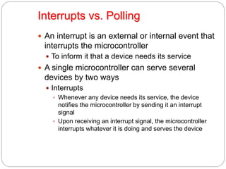
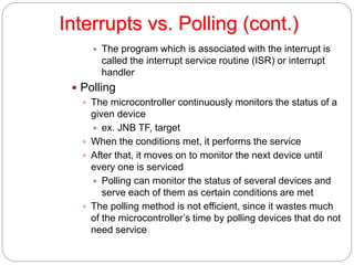
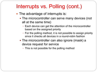
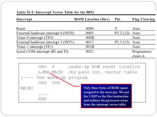
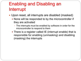
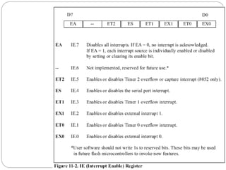
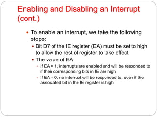
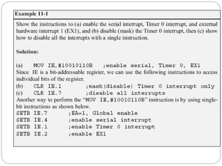
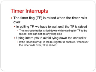
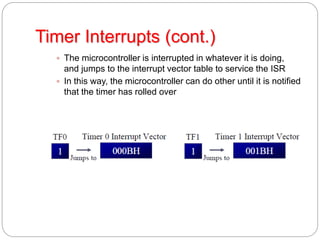
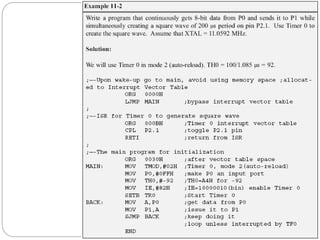
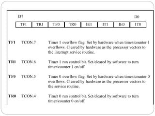
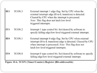
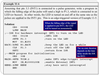
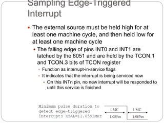
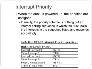
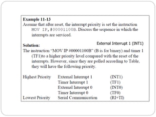
INTERRUPTS
PROGRAMMING
by
E.M.Roopa Devi
Kongu Engineering College
Interrupts vs. Polling
 An interrupt is an external or internal event that
interrupts the microcontroller
 To inform it that a device needs its service
 A single microcontroller can serve several
devices by two ways
 Interrupts
 Whenever any device needs its service, the device
notifies the microcontroller by sending it an interrupt
signal
 Upon receiving an interrupt signal, the microcontroller
interrupts whatever it is doing and serves the device
Interrupts vs. Polling (cont.)
 The program which is associated with the interrupt is
called the interrupt service routine (ISR) or interrupt
handler
 Polling
 The microcontroller continuously monitors the status of a
given device
 ex. JNB TF, target
 When the conditions met, it performs the service
 After that, it moves on to monitor the next device until
every one is serviced
 Polling can monitor the status of several devices and
serve each of them as certain conditions are met
 The polling method is not efficient, since it wastes much
of the microcontroller’s time by polling devices that do not
need service
Interrupts vs. Polling (cont.)
 The advantage of interrupts is:
 The microcontroller can serve many devices (not
all at the same time)
 Each device can get the attention of the microcontroller
based on the assigned priority
 For the polling method, it is not possible to assign priority
since it checks all devices in a round-robin fashion
 The microcontroller can also ignore (mask) a
device request for service
 This is not possible for the polling method
Interrupt Service Routine
 For every interrupt, there must be an interrupt
service routine (ISR), or interrupt handler
 When an interrupt is invoked, the microcontroller
runs the interrupt service routine
 There is a fixed location in memory that holds the
address of its ISR
 The group of memory locations set aside to hold the
addresses of ISRs is called interrupt vector table
Steps in Executing an Interrupt
 Upon activation of an interrupt, the
microcontroller goes through:
 It finishes the instruction it is executing and saves
the address of the next instruction (PC) on the
stack
 It also saves the current status of all the registers
internally (not on the stack)
 It jumps to a fixed location in memory, called the
interrupt vector table, that holds the address of
the ISR
Steps in Executing an Interrupt
(cont.)
 It gets the address of the ISR from the interrupt
vector table and jumps to ISR
 It starts to execute the interrupt service subroutine until it
reaches the last instruction of the subroutine which is
RETI (return from interrupt)
 Upon executing the RETI instruction, the
microcontroller returns to the place where it was
interrupted
 It gets the program counter (PC) address from the stack
by popping the top two bytes of the stack into the PC
 It starts to execute from that address
Six Interrupts in 8051
 Six interrupts are allocated as follows
 Reset – power-up reset
 Two interrupts are set aside for the timers:
 One for timer 0 and one for timer 1
 Two interrupts are set aside for hardware external
interrupts
 P3.2 and P3.3 are for the external hardware interrupts INT0
(or EX1), and INT1 (or EX2)
 Serial communication has a single interrupt that
belongs to both receive and transfer
Enabling and Disabling an
Interrupt
 Upon reset, all interrupts are disabled (masked)
 None will be responded to by the microcontroller if
they are activated
 The interrupts must be enabled by software in order for the
microcontroller to respond to them
 There is a register called IE (interrupt enable) that is
responsible for enabling (unmasking) and disabling
(masking) the interrupts
Enabling and Disabling an Interrupt
(cont.)
 To enable an interrupt, we take the following
steps:
 Bit D7 of the IE register (EA) must be set to high
to allow the rest of register to take effect
 The value of EA
 If EA = 1, interrupts are enabled and will be responded to
if their corresponding bits in IE are high
 If EA = 0, no interrupt will be responded to, even if the
associated bit in the IE register is high
Timer Interrupts
 The timer flag (TF) is raised when the timer rolls
over
 In polling TF, we have to wait until the TF is raised
 The microcontroller is tied down while waiting for TF to be
raised, and can not do anything else
 Using interrupts to avoid tying down the controller
 If the timer interrupt in the IE register is enabled, whenever
the timer rolls over, TF is raised
Timer Interrupts (cont.)
 The microcontroller is interrupted in whatever it is doing,
and jumps to the interrupt vector table to service the ISR
 In this way, the microcontroller can do other until it is notified
that the timer has rolled over
Triggering* means making a circuit active.
In level triggering the circuit will become
active when the gating or clock pulse is on a
particular level.
In edge triggering the circuit becomes
active at negative or positive edge of the
clock signal.
External Hardware Interrupts
 The 8051 has two external hardware interrupts
 Pin 12 (P3.2) and pin 13 (P3.3) of the 8051
 Designated as INT0 and INT1
 Used as external hardware interrupts
 The interrupt vector table locations 0003H and
0013H are set aside for INT0 and INT1
 There are two activation levels for the external
hardware interrupts
 Level trigged
 Edge trigged
Level-Triggered Interrupt
 INT0 and INT1 pins are normally high
 If a low-level signal is applied to them, it triggers
the interrupt
 The microcontroller stops whatever it is doing and jumps
to the interrupt vector table to service that interrupt
 The low-level signal at the INT pin must be removed
before the execution of the last instruction of the ISR,
RETI
 Otherwise, another interrupt will be generated
 This is called a level-triggered or level-activated interrupt
and is the default mode upon reset
Sampling Low Level-Triggered
Interrupt
 P3.2 and P3.3 are used for normal I/O
 Unless the INT0 and INT1 bits in the IE register
are enabled
 After the hardware interrupts are enabled, the controller
keeps sampling the INTn pin for a low-level signal once
each machine cycle
 The pin must be held in a low state until the start of the
execution of ISR
 If the INTn pin is brought back to a logic high before
the start of the execution of ISR, there will be no
interrupt
 If INTn pin is left at a logic low after the RETI instruction
of the ISR, another interrupt will be activated after one
instruction is executed
Sampling Low Level-Triggered
Interrupt (cont.)
 To ensure the activation of the hardware
interrupt at the INTn pin,
 The duration of the low-level signal is around 4
machine cycles, but no more
 This is due to the fact that the level-triggered interrupt is
not latched
 Thus the pin must be held in a low state until the start of
the ISR execution
Edge-Triggered Interrupt
 To make INT0 and INT1 edge-triggered
interrupts, we must program the bits of the
TCON register
 The TCON register holds the IT0 and IT1 flag bits
that determine level- or edge-triggered mode of
the hardware interrupt
 IT0 and IT1 are bits D0 and D2 of TCON
 They are also referred to as TCON.0 and TCON.2
since the TCON register is bit-addressable
Sampling Edge-Triggered
Interrupt
 The external source must be held high for at
least one machine cycle, and then held low for
at least one machine cycle
 The falling edge of pins INT0 and INT1 are
latched by the 8051 and are held by the TCON.1
and TCON.3 bits of TCON register
 Function as interrupt-in-service flags
 It indicates that the interrupt is being serviced now
 On this INTn pin, no new interrupt will be responded to
until this service is finished
Sampling Edge-Triggered Interrupt
(cont.)
 When the ISRs are finished, TCON.1 and
TCON.3 are cleared
 The interrupt is finished and the 8051 is ready to
respond to another interrupt on that pin
 During the time that the interrupt service routine is being
executed, the INTn pin is ignored, no matter how many
times it makes a high-to-low transition
 RETI clears the corresponding bit in TCON
register (TCON.1 or TCON.3)
 There is no need for instruction CLR TCON.1 before
RETI in the ISR associated with INT0
Serial Communication Interrupt
 TI (transfer interrupt) is raised when the stop bit
is transferred
 Indicating that the SBUF register is ready to transfer
the next byte
 RI (received interrupt) is raised when the stop bit
is received
 Indicating that the received byte needs to be picked
up before it is lost (overrun) by new incoming serial
data
RI and TI Flags and Interrupts
 In the 8051 there is only one interrupt set aside
for serial communication
 Used to both send and receive data
 If the interrupt bit in the IE register (IE.4) is
enabled, when RI or TI is raised the 8051 gets
interrupted and jumps to memory location 0023H
to execute the ISR
 In that ISR we must examine the TI and RI flags to see
which one caused the interrupt and respond accordingly
Use of Serial COM in 8051
 The serial interrupt is used mainly for receiving
data and is never used for sending data serially
 This is like getting a telephone call in which we
need a ring to be notified
 If we need to make a phone call there are other
ways to remind ourselves and there is no need for
ringing
 However in receiving the phone call, we must
respond immediately no matter what we are doing
or we will miss the call
TRANS: RETI
END
HERE: JNB TI, HERE
CLR TI
SJMP BACK
TRANS: RETI
END
Interrupt Flag Bits
 The TCON register holds four of the interrupt
flags in the 8051
 The SCON register has the RI and TI flags
Interrupt Priority
 When the 8051 is powered up, the priorities are
assigned
 In reality, the priority scheme is nothing but an
internal polling sequence in which the 8051 polls
the interrupts in the sequence listed and responds
accordingly
Altering Interrupt Priority
 We can alter the sequence of interrupt priority
by programming a register called IP (interrupt
priority)
 To give a higher priority to any of the interrupts,
we make the corresponding bit in the IP register
high
 When two or more interrupt bits in the IP register
are set to high
 While these interrupts have a higher priority than others,
they are serviced according to the sequence of Table 11-
13
External Interrupt 1 (INT1)
Interrupt inside an Interrupt
 In the 8051 a low-priority interrupt can be
interrupted by a higher-priority interrupt but not by
another low priority interrupt
 Although all the interrupts are latched and kept
internally, no low-priority interrupt can get the
immediate attention of the CPU until the 8051 has
finished servicing the high-priority interrupts
Triggering Interrupt by Software
 To test an ISR by way of simulation can be done
with simple instructions to set the interrupts high
 Thereby cause the 8051 to jump to the interrupt
vector table
 ex. If the IE bit for timer 1 is set, an instruction such
as SETB TF1 will interrupt the 8051 in whatever it is
doing and will force it to jump to the interrupt vector
table
 We do not need to wait for timer 1 go roll over to have an
interrupt

Interrupt in 8051

  • 1.
  • 2.
    Interrupts vs. Polling An interrupt is an external or internal event that interrupts the microcontroller  To inform it that a device needs its service  A single microcontroller can serve several devices by two ways  Interrupts  Whenever any device needs its service, the device notifies the microcontroller by sending it an interrupt signal  Upon receiving an interrupt signal, the microcontroller interrupts whatever it is doing and serves the device
  • 3.
    Interrupts vs. Polling(cont.)  The program which is associated with the interrupt is called the interrupt service routine (ISR) or interrupt handler  Polling  The microcontroller continuously monitors the status of a given device  ex. JNB TF, target  When the conditions met, it performs the service  After that, it moves on to monitor the next device until every one is serviced  Polling can monitor the status of several devices and serve each of them as certain conditions are met  The polling method is not efficient, since it wastes much of the microcontroller’s time by polling devices that do not need service
  • 4.
    Interrupts vs. Polling(cont.)  The advantage of interrupts is:  The microcontroller can serve many devices (not all at the same time)  Each device can get the attention of the microcontroller based on the assigned priority  For the polling method, it is not possible to assign priority since it checks all devices in a round-robin fashion  The microcontroller can also ignore (mask) a device request for service  This is not possible for the polling method
  • 5.
    Interrupt Service Routine For every interrupt, there must be an interrupt service routine (ISR), or interrupt handler  When an interrupt is invoked, the microcontroller runs the interrupt service routine  There is a fixed location in memory that holds the address of its ISR  The group of memory locations set aside to hold the addresses of ISRs is called interrupt vector table
  • 6.
    Steps in Executingan Interrupt  Upon activation of an interrupt, the microcontroller goes through:  It finishes the instruction it is executing and saves the address of the next instruction (PC) on the stack  It also saves the current status of all the registers internally (not on the stack)  It jumps to a fixed location in memory, called the interrupt vector table, that holds the address of the ISR
  • 7.
    Steps in Executingan Interrupt (cont.)  It gets the address of the ISR from the interrupt vector table and jumps to ISR  It starts to execute the interrupt service subroutine until it reaches the last instruction of the subroutine which is RETI (return from interrupt)  Upon executing the RETI instruction, the microcontroller returns to the place where it was interrupted  It gets the program counter (PC) address from the stack by popping the top two bytes of the stack into the PC  It starts to execute from that address
  • 8.
    Six Interrupts in8051  Six interrupts are allocated as follows  Reset – power-up reset  Two interrupts are set aside for the timers:  One for timer 0 and one for timer 1  Two interrupts are set aside for hardware external interrupts  P3.2 and P3.3 are for the external hardware interrupts INT0 (or EX1), and INT1 (or EX2)  Serial communication has a single interrupt that belongs to both receive and transfer
  • 10.
    Enabling and Disablingan Interrupt  Upon reset, all interrupts are disabled (masked)  None will be responded to by the microcontroller if they are activated  The interrupts must be enabled by software in order for the microcontroller to respond to them  There is a register called IE (interrupt enable) that is responsible for enabling (unmasking) and disabling (masking) the interrupts
  • 12.
    Enabling and Disablingan Interrupt (cont.)  To enable an interrupt, we take the following steps:  Bit D7 of the IE register (EA) must be set to high to allow the rest of register to take effect  The value of EA  If EA = 1, interrupts are enabled and will be responded to if their corresponding bits in IE are high  If EA = 0, no interrupt will be responded to, even if the associated bit in the IE register is high
  • 14.
    Timer Interrupts  Thetimer flag (TF) is raised when the timer rolls over  In polling TF, we have to wait until the TF is raised  The microcontroller is tied down while waiting for TF to be raised, and can not do anything else  Using interrupts to avoid tying down the controller  If the timer interrupt in the IE register is enabled, whenever the timer rolls over, TF is raised
  • 15.
    Timer Interrupts (cont.) The microcontroller is interrupted in whatever it is doing, and jumps to the interrupt vector table to service the ISR  In this way, the microcontroller can do other until it is notified that the timer has rolled over
  • 17.
    Triggering* means makinga circuit active. In level triggering the circuit will become active when the gating or clock pulse is on a particular level. In edge triggering the circuit becomes active at negative or positive edge of the clock signal.
  • 18.
    External Hardware Interrupts The 8051 has two external hardware interrupts  Pin 12 (P3.2) and pin 13 (P3.3) of the 8051  Designated as INT0 and INT1  Used as external hardware interrupts  The interrupt vector table locations 0003H and 0013H are set aside for INT0 and INT1  There are two activation levels for the external hardware interrupts  Level trigged  Edge trigged
  • 19.
    Level-Triggered Interrupt  INT0and INT1 pins are normally high  If a low-level signal is applied to them, it triggers the interrupt  The microcontroller stops whatever it is doing and jumps to the interrupt vector table to service that interrupt  The low-level signal at the INT pin must be removed before the execution of the last instruction of the ISR, RETI  Otherwise, another interrupt will be generated  This is called a level-triggered or level-activated interrupt and is the default mode upon reset
  • 22.
    Sampling Low Level-Triggered Interrupt P3.2 and P3.3 are used for normal I/O  Unless the INT0 and INT1 bits in the IE register are enabled  After the hardware interrupts are enabled, the controller keeps sampling the INTn pin for a low-level signal once each machine cycle  The pin must be held in a low state until the start of the execution of ISR  If the INTn pin is brought back to a logic high before the start of the execution of ISR, there will be no interrupt  If INTn pin is left at a logic low after the RETI instruction of the ISR, another interrupt will be activated after one instruction is executed
  • 23.
    Sampling Low Level-Triggered Interrupt(cont.)  To ensure the activation of the hardware interrupt at the INTn pin,  The duration of the low-level signal is around 4 machine cycles, but no more  This is due to the fact that the level-triggered interrupt is not latched  Thus the pin must be held in a low state until the start of the ISR execution
  • 24.
    Edge-Triggered Interrupt  Tomake INT0 and INT1 edge-triggered interrupts, we must program the bits of the TCON register  The TCON register holds the IT0 and IT1 flag bits that determine level- or edge-triggered mode of the hardware interrupt  IT0 and IT1 are bits D0 and D2 of TCON  They are also referred to as TCON.0 and TCON.2 since the TCON register is bit-addressable
  • 28.
    Sampling Edge-Triggered Interrupt  Theexternal source must be held high for at least one machine cycle, and then held low for at least one machine cycle  The falling edge of pins INT0 and INT1 are latched by the 8051 and are held by the TCON.1 and TCON.3 bits of TCON register  Function as interrupt-in-service flags  It indicates that the interrupt is being serviced now  On this INTn pin, no new interrupt will be responded to until this service is finished
  • 29.
    Sampling Edge-Triggered Interrupt (cont.) When the ISRs are finished, TCON.1 and TCON.3 are cleared  The interrupt is finished and the 8051 is ready to respond to another interrupt on that pin  During the time that the interrupt service routine is being executed, the INTn pin is ignored, no matter how many times it makes a high-to-low transition  RETI clears the corresponding bit in TCON register (TCON.1 or TCON.3)  There is no need for instruction CLR TCON.1 before RETI in the ISR associated with INT0
  • 32.
    Serial Communication Interrupt TI (transfer interrupt) is raised when the stop bit is transferred  Indicating that the SBUF register is ready to transfer the next byte  RI (received interrupt) is raised when the stop bit is received  Indicating that the received byte needs to be picked up before it is lost (overrun) by new incoming serial data
  • 33.
    RI and TIFlags and Interrupts  In the 8051 there is only one interrupt set aside for serial communication  Used to both send and receive data  If the interrupt bit in the IE register (IE.4) is enabled, when RI or TI is raised the 8051 gets interrupted and jumps to memory location 0023H to execute the ISR  In that ISR we must examine the TI and RI flags to see which one caused the interrupt and respond accordingly
  • 34.
    Use of SerialCOM in 8051  The serial interrupt is used mainly for receiving data and is never used for sending data serially  This is like getting a telephone call in which we need a ring to be notified  If we need to make a phone call there are other ways to remind ourselves and there is no need for ringing  However in receiving the phone call, we must respond immediately no matter what we are doing or we will miss the call
  • 35.
  • 37.
    HERE: JNB TI,HERE CLR TI SJMP BACK TRANS: RETI END
  • 38.
    Interrupt Flag Bits The TCON register holds four of the interrupt flags in the 8051  The SCON register has the RI and TI flags
  • 39.
    Interrupt Priority  Whenthe 8051 is powered up, the priorities are assigned  In reality, the priority scheme is nothing but an internal polling sequence in which the 8051 polls the interrupts in the sequence listed and responds accordingly
  • 41.
    Altering Interrupt Priority We can alter the sequence of interrupt priority by programming a register called IP (interrupt priority)  To give a higher priority to any of the interrupts, we make the corresponding bit in the IP register high  When two or more interrupt bits in the IP register are set to high  While these interrupts have a higher priority than others, they are serviced according to the sequence of Table 11- 13
  • 44.
  • 45.
    Interrupt inside anInterrupt  In the 8051 a low-priority interrupt can be interrupted by a higher-priority interrupt but not by another low priority interrupt  Although all the interrupts are latched and kept internally, no low-priority interrupt can get the immediate attention of the CPU until the 8051 has finished servicing the high-priority interrupts
  • 46.
    Triggering Interrupt bySoftware  To test an ISR by way of simulation can be done with simple instructions to set the interrupts high  Thereby cause the 8051 to jump to the interrupt vector table  ex. If the IE bit for timer 1 is set, an instruction such as SETB TF1 will interrupt the 8051 in whatever it is doing and will force it to jump to the interrupt vector table  We do not need to wait for timer 1 go roll over to have an interrupt