Downloaded 623 times

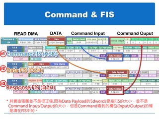
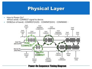
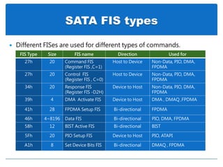
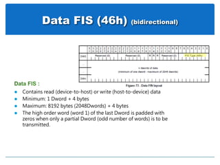
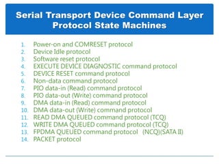
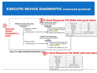
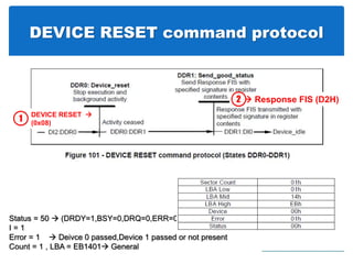
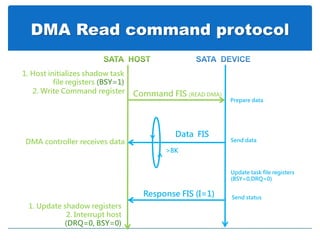
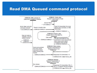
![Read DMA Queued command protocol
Response FIS (Status=50)
Response FIS ( I=1 , Status=50?)
Interrupt host (BSY=0,DRQ=0)
1. Host initializes DMA controller
(BSY=1)
( BSY=01 ,REL= Count[2]=1,
I/O = Count[1] = 0 , Count[0]=1 ,
I=1 if release interrupt enabled )
2. Send READ DMA QUEUED Command
Count[7:3] = TAG
Response FIS ( Status=58, Count[7:3]=TAG )
(BSY=0,DRQ=1)
Update task file registers
(BSY=0,DRQ=0)
(BSY=1)
1. Interrupt host
2. Host deactivates 3rd DMA controller
3. Host issue SERVICE command
>8K
Read TAG & backup DMA controller context
Queue command
Command FIS (READ DMA QUEUED)
Set Device Bits FIS ( SERV=1 , I=1 )Device is ready to transfer data
& Service request
Command FIS (SERVICE)
Host release bus / command
(BSY=0,DRQ=1)
(BSY=0)
more commads
Data FIS Send data
DMA controller receives data
( REL= Count[2]=0,
I/O = Count[1] = 1 ,
Count[0]=0)
( REL= Count[2]=0,
I/O = Count[1] = 1 ,
Count[0]=1)
Response with command that
ready to execute
Device processing data
Wait for the CPU to respond to the interrupt Deactivate the 3rd party DMA engine
Send status
last command queued in(BSY=1)
more queued commands not complete](https://image.slidesharecdn.com/satabytc-160426082734/85/SATA-Introduction-35-320.jpg)
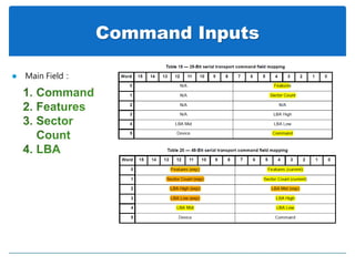
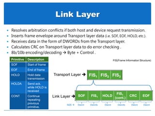
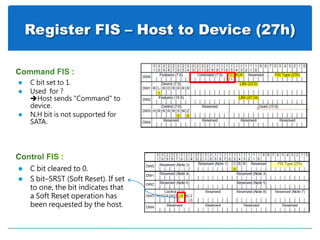
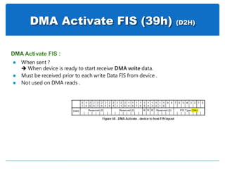
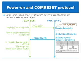
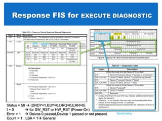
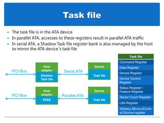
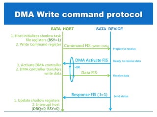
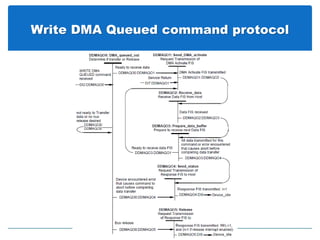
![Write DMA Queued command protocol
Response FIS (Status=50)
Response FIS ( I=1 , Status=50?)
Interrupt host (BSY=0,DRQ=0)
1. Host initializes DMA controller
(BSY=1)
( BSY=01 ,REL= Count[2]=1,
I/O = Count[1] = 0 , Count[0]=1 ,
I=1 if release interrupt enabled )
2. Send READ DMA QUEUED Command
Count[7:3] = TAG
Response FIS ( Status=58, Count[7:3]=TAG )
(BSY=0,DRQ=1)
Update task file registers
(BSY=0,DRQ=0)
(BSY=1)
1. Interrupt host
2. Host deactivates DMA
controller
3. Host issue SERVICE command
>8K
Read TAG & restore DMA controller context
Queue command
Command FIS (WRITE DMA QUEUED)
Set Device Bits FIS ( SERV=1 , I=1 ) Device is ready to transfer data
& Service request
Command FIS (SERVICE)
Host release bus / command
(BSY=0,DRQ=1)
(BSY=0)
more commads
DMA Activate FIS
Receive data
DMA controller sends data
( REL= Count[2]=0,
I/O = Count[1] = 1 ,
Count[0]=0)
( REL= Count[2]=0,
I/O = Count[1] = 1 ,
Count[0]=1)
Response with command that
ready to execute
Send status
last command queued in(BSY=1)
more queued commands not complete](https://image.slidesharecdn.com/satabytc-160426082734/85/SATA-Introduction-36-320.jpg)
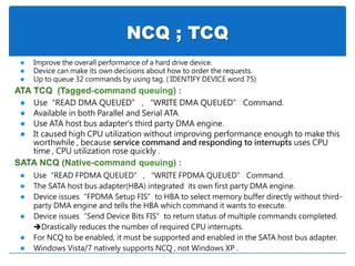
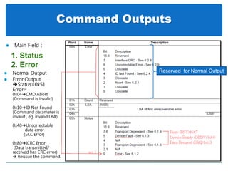
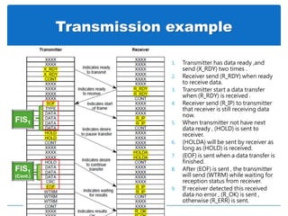
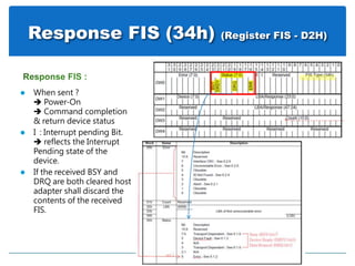
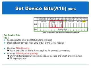
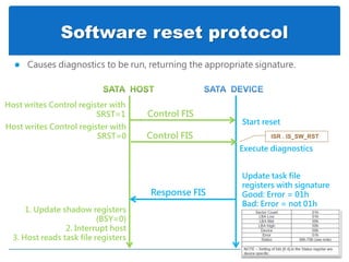
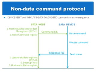
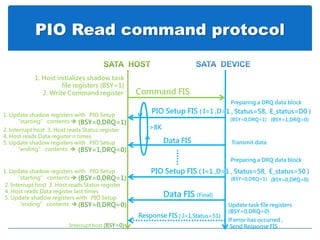
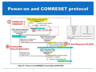
![FPDMA Read command protocol
Response FIS (Status=50)
Interrupt host (BSY=0,DRQ=0)
(BSY=0)
( BSY=0 ,DRQ= 0 , I=0 )
Send READ FPDMA QUEUED Command
Count[7:3] = NCQ TAG (BSY=1)
Update task file registers
(BSY=0)
Select the DMA engine context by TAG
(DMA Buffer ID)
Host loads PRD pointer into DMA engine
DMA controller receives data
Command FIS (READ FPDMA QUEUED)
Host sets SActive Register
(BSY=0)
more commads
Data FIS
Send data
DMA Setup FIS
Set Device Bits FIS (BSY=0 , I=1 , SActive )
(DMA Buffer ID= TAG , D=1 , I=0,
Transfer count )
this command not complete
Transfer count not exhausted
bit n in SActive field set to one
where n = TAG for each command
TAG value that has completed
Queue command
& store NCQ TAG in SActive
Send status
Multiple commands can be indicated as complete at a time
more queued commands not complete
Update Host copy SActive Register](https://image.slidesharecdn.com/satabytc-160426082734/85/SATA-Introduction-38-320.jpg)
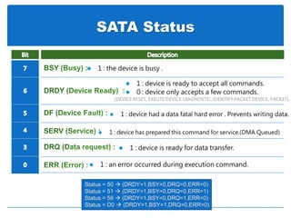
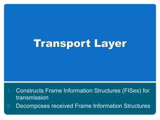
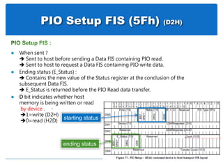
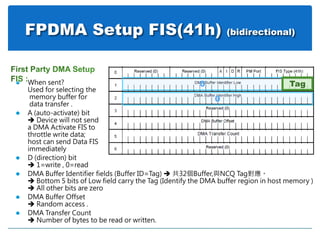
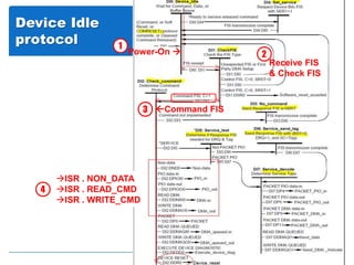
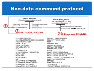
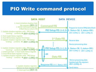
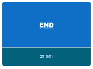
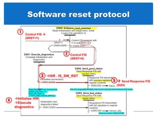
![FPDMA Write command protocol
Response FIS (Status=50)
Interrupt host (BSY=0,DRQ=0)
(BSY=0)
( BSY=0 ,DRQ= 0 , I=0 )
Send WRITE FPDMA QUEUED Command
Count[7:3] = NCQ TAG (BSY=1)
Update task file registers
(BSY=0)
Select the DMA engine context by TAG
(DMA Buffer ID)
Host loads PRD pointer into DMA engine
DMA controller sends data
Command FIS (WRITE FPDMA QUEUED)
(BSY=0)
more commads
DMA Activate FIS
Receive data
DMA Setup FIS
Set Device Bits FIS (BSY=0 , I=1 ,SActive)
(DMA Buffer ID= TAG , D=0 , I=0,
Auto-Activate=1 ,Transfer count )
this command not complete
Transfer count not exhausted
bit n in SActive field set to one
where n = TAG for each command
TAG value that has completed
Queue command
& store NCQ TAG in SActive
Data FIS
if Auto-Activate==0
Send status
more queued commands not complete
Multiple commands can be indicated as complete at a time
Host sets SActive Register
Update Host copy SActive Register](https://image.slidesharecdn.com/satabytc-160426082734/85/SATA-Introduction-39-320.jpg)
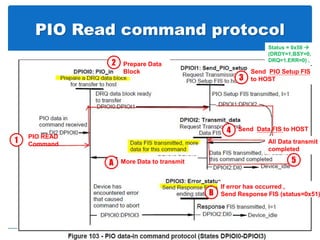
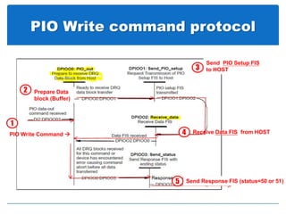
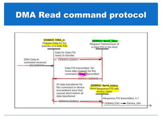
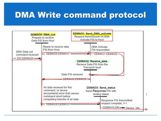

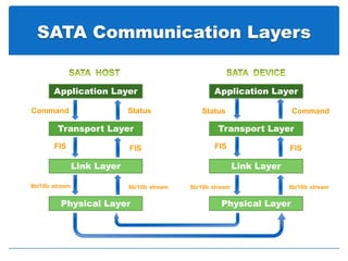
This document discusses the different communication layers in Serial ATA (SATA), including the physical, link, transport, and command layers. It provides details on the Frame Information Structure (FIS) types used at each layer for various command types like PIO read, PIO write, DMA read, and DMA write. It also explains the command sequences and state machines involved in operations like non-data commands, software reset, and device idle protocol.


![谷歌留痕技术教程[ 𝙩𝙤𝙥 𝟮𝟯𝟯. 𝙘 𝙤𝙢 ]](https://cdn.slidesharecdn.com/ss_thumbnails/top233-260130173900-2eb784f9-thumbnail.jpg?width=640&height=640&fit=bounds)


