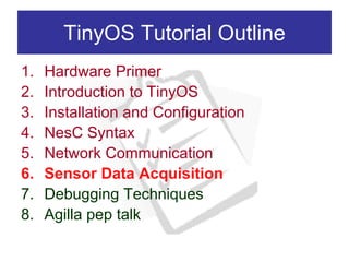
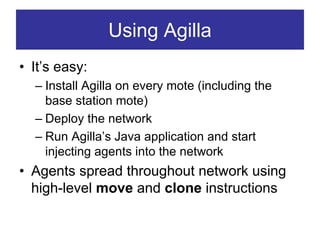
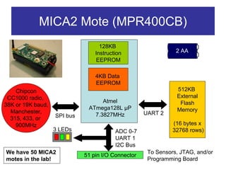
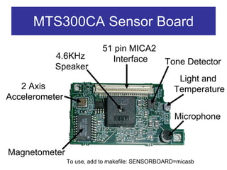
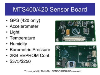
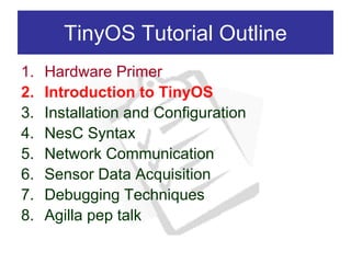
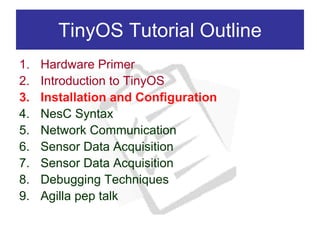
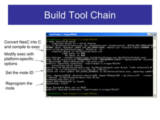
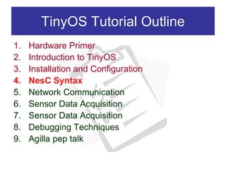
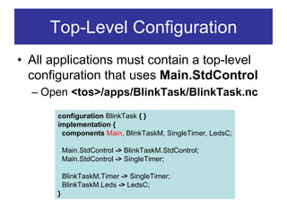
This document provides an outline for a TinyOS tutorial that introduces the TinyOS operating system and development environment. It covers the hardware primer, introduction to TinyOS, installation and configuration, NesC syntax, network communication, sensor data acquisition, debugging techniques, and concludes with an overview of the Agilla mobile agent system. The outline includes 10 sections that will guide students through understanding the TinyOS hardware platforms, programming model, components, interfaces, and building/installing applications.
![Module Syntax: Interface
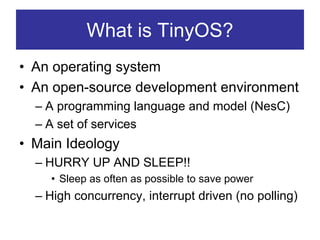
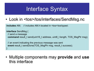
• Look in <tos>/tos/system/AMStandard.nc
module AMStandard {
provides {
interface StdControl as Control;
interface SendMsg[uint8_t id]; // parameterized by AM ID
command uint16_t activity(); // # of packets sent in past second
…
Component
}
Interface
uses {
event result_t sendDone();
interface StdControl as UARTControl;
…
}
}
implementation {
…// code implementing all provided commands and used events
}](https://image.slidesharecdn.com/tostutorial-120308005733-phpapp01/85/Tos-tutorial-28-320.jpg)
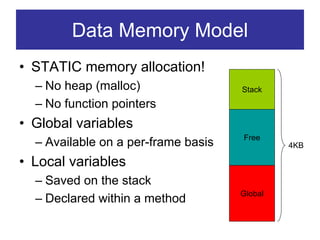
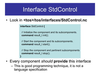
![Module Syntax: Implementation
module AMStandard {
provides { interface SendMsg[uint8_t id]; … }
uses {event result_t sendDone(); … }
}
implementation {
task void sendTask() {
…
signal sendDone(); signal SendMsg.SendDone(….);
}
command result_t SendMsg.send[uint8_t id](uint16_t addr,
uint8_t length, TOS_MsgPtr data) {
…
post sendTask();
…
return SUCCESS;
}
default event result_t sendDone() { return SUCCESS; }
}](https://image.slidesharecdn.com/tostutorial-120308005733-phpapp01/85/Tos-tutorial-29-320.jpg)
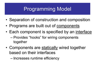
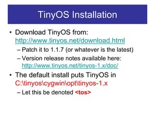
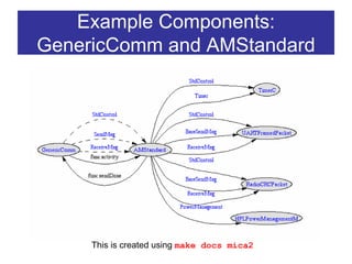
![Configuration Syntax: Interface
• Look in <tos>/tos/system/GenericComm.nc
configuration GenericComm {
provides {
interface StdControl as Control;
Component interface SendMsg[uint8_t id]; //parameterized by active message id
Interface interface ReceiveMsg[uint8_t id];
command uint16_t activity();
}
uses { event result_t sendDone();}
}
implementation {
components AMStandard, RadioCRCPacket as RadioPacket, TimerC,
Component
NoLeds as Leds, UARTFramedPacket as UARTPacket,
Selection
HPLPowerManagementM;
… // code wiring the components together
}](https://image.slidesharecdn.com/tostutorial-120308005733-phpapp01/85/Tos-tutorial-31-320.jpg)
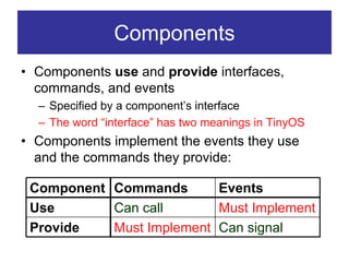
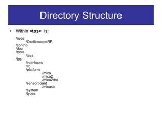
![Configuration Syntax: Wiring
• Still in <tos>/tos/system/GenericComm.nc
configuration GenericComm {
provides {
interface StdControl as Control;
interface SendMsg[uint8_t id]; //parameterized by active message id
command uint16_t activity(); …
}
uses {event result_t sendDone(); …}
}
implementation {
components AMStandard, TimerC, …;
Control = AMStandard.Control;
SendMsg = AMStandard.SendMsg;
activity = AMStandard.activity;
AMStandard.TimerControl -> TimerC.StdControl;
AMStandard.ActivityTimer -> TimerC.Timer[unique("Timer")]; …
}](https://image.slidesharecdn.com/tostutorial-120308005733-phpapp01/85/Tos-tutorial-32-320.jpg)
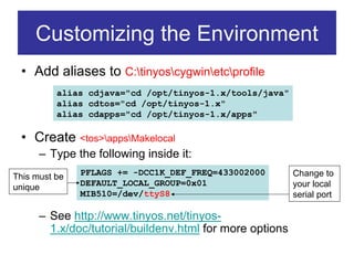
![Fan-Out and Fan-In
• A user can be mapped to multiple providers (fan-out)
– Open <tos>appsCntToLedsAndRfmCntToLedsAndRfm.nc
configuration CntToLedsAndRfm { }
implementation {
components Main, Counter, IntToLeds, IntToRfm, TimerC;
Main.StdControl -> Counter.StdControl;
Main.StdControl -> IntToLeds.StdControl;
Main.StdControl -> IntToRfm.StdControl;
Main.StdControl -> TimerC.StdControl;
Counter.Timer -> TimerC.Timer[unique("Timer")];
IntToLeds <- Counter.IntOutput;
Counter.IntOutput -> IntToRfm;
}
• A provider can be mapped to multiple users (fan-in)](https://image.slidesharecdn.com/tostutorial-120308005733-phpapp01/85/Tos-tutorial-34-320.jpg)
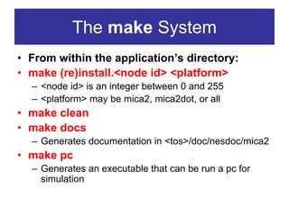
![Potential Fan-Out Bug
• Whenever you fan-out/in an interface,
ensure the return value has a combination
function
– Can do:
App.Leds -> LedsC;
App.Leds -> NoLeds;
– CANNOT do:
AppOne.ReceiveMsg -> GenericComm.ReceiveMsg[12];
AppTwo.ReceiveMsg -> GenericComm.ReceiveMsg[12];](https://image.slidesharecdn.com/tostutorial-120308005733-phpapp01/85/Tos-tutorial-35-320.jpg)
![TOS Active Messages
• TOS uses active typedef struct TOS_Msg {
// the following are transmitted
messages as defined in uint16_t addr;
<tos>/system/types/AM.h uint8_t type;
• Message is “active” uint8_t group;
because it contains the uint8_t length;
int8_t data[TOSH_DATA_LENGTH];
destination address, uint16_t crc;
group ID, and type // the following are not transmitted
• TOSH_DATA_LENGTH = uint16_t strength;
29 bytes uint8_t ack;
uint16_t time;
– Can change via
uint8_t sendSecurityMode;
MSG_SIZE=x in Makefile
uint8_t receiveSecurityMode;
– Max 36 } TOS_Msg;
Header (5) Payload (29) CRC](https://image.slidesharecdn.com/tostutorial-120308005733-phpapp01/85/Tos-tutorial-40-320.jpg)
![Active Messaging (Cont.)
AM Handler AM Handler AM Handler
Application 47 48 49
Tos_Msg[AM=47] signal[48]
signal[47] signal[49]
GenericComm GenericComm
AMStandard AMStandard
Radio Stack, TX Radio Stack, RX
Wireless](https://image.slidesharecdn.com/tostutorial-120308005733-phpapp01/85/Tos-tutorial-41-320.jpg)
![Sending a message (1 of 3)
• First create a .h file with a struct defining
the message data format, and a unique
active message number
– Open <tos>/apps/Oscilloscope/OscopeMsg.h
struct OscopeResetMsg
struct OscopeMsg
{
{
/* Empty payload! */
uint16_t sourceMoteID;
};
uint16_t lastSampleNumber;
uint16_t channel;
enum {
uint16_t data[BUFFER_SIZE];
AM_OSCOPEMSG = 10,
};
AM_OSCOPERESETMSG = 32
};](https://image.slidesharecdn.com/tostutorial-120308005733-phpapp01/85/Tos-tutorial-43-320.jpg)
![Sending a Message (2 of 3)
module OscilloscopeM { …
uses interface SendMsg as DataMsg; …
}
implementation{
TOS_Msg msg; …
task void dataTask() {
struct OscopeMsg *pack = (struct OscopeMsg *)msg.data;
… // fill up the message
call DataMsg.send(TOS_BCAST_ADDR, sizeof(struct OscopeMsg),
&msg[currentMsg]);
}
event result_t DataMsg.sendDone(TOS_MsgPtr sent, result_t success) {
return SUCCESS;
}
}
Question: How does TOS know the AM number?](https://image.slidesharecdn.com/tostutorial-120308005733-phpapp01/85/Tos-tutorial-44-320.jpg)
![Sending a Message (3 of 3)
• The AM number is determined by the
configuration file
– Open <tos>/apps/OscilloscopeRF/Oscilloscope.nc
configuration Oscilloscope { }
implementation {
components Main, OscilloscopeM, GenericComm as Comm, …;
…
OscilloscopeM.DataMsg -> Comm.SendMsg[AM_OSCOPEMSG];
}](https://image.slidesharecdn.com/tostutorial-120308005733-phpapp01/85/Tos-tutorial-45-320.jpg)
![Receiving a Message
configuration Oscilloscope { }
implementation {
components Main, OscilloscopeM, UARTComm as Comm, ….;
…
OscilloscopeM.ResetCounterMsg ->
Comm.ReceiveMsg[AM_OSCOPERESETMSG];
}
module OscilloscopeM {
uses interface ReceiveMsg as ResetCounterMsg; …
}
implementation {
uint16_t readingNumber;
event TOS_MsgPtr ResetCounterMsg.receive(TOS_MsgPtr m) {
atomic { readingNumber = 0; }
return m;
}
}](https://image.slidesharecdn.com/tostutorial-120308005733-phpapp01/85/Tos-tutorial-46-320.jpg)
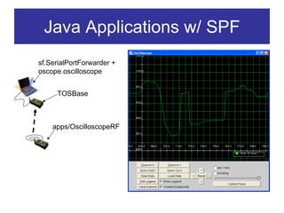
![MIG
• Message Interface Generator
– Generates a Java class representing a TOS message
– Located in /usr/local/bin This is the generator as defined in
/usr/local/lib/ncc/gen*.pm
– Usage:
mig –java-classname=[classname] java [filename.h] [struct name] > outputFile
• Normally, you allow the Makefile to generate the
Message classes
OscopeMsg.java:
$(MIG) -java-classname=$(PACKAGE).OscopeMsg
$(APP)/OscopeMsg.h OscopeMsg -o $@
$(JAVAC) $@](https://image.slidesharecdn.com/tostutorial-120308005733-phpapp01/85/Tos-tutorial-51-320.jpg)