Downloaded 1,729 times


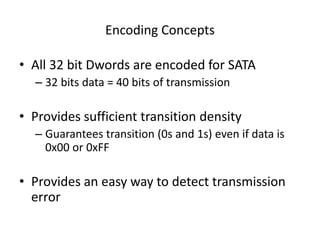
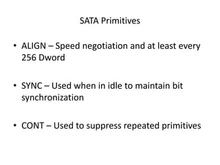
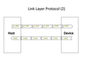


![BIST Activate FIS
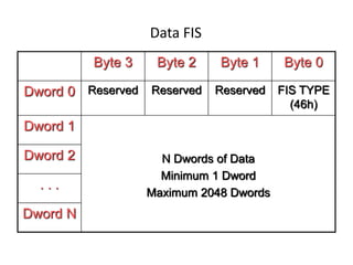
Byte 3 Byte 2 Byte 1 Byte 0
0 Reserved [ TASLFPRV ] Reserved FIS Type 58h
1 Data [31:24] Data [23:16] Data [15:8] Data [7:0]
2 Data [31:24] Data [23:16] Data [15:8] Data [7:0]
T - Far end transmit only – transmit Dwords defined in words 1 & 2
A - No ALIGN transmission (valid only with T)
S - Bypass scrambling (valid only with T)
L - Far end retimed loopback with ALIGN insertion
F - Far end analog loopback
P - Transmit primitives defined in words 1 & 2 of the FIS
R - Reserved
V - Vendor Unique Test Mode – other bits undefined](https://image.slidesharecdn.com/sata-140613142548-phpapp02/85/SATA-Protocol-60-320.jpg)


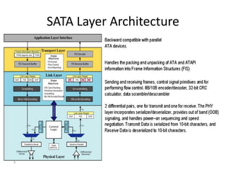
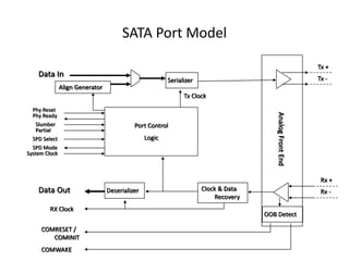
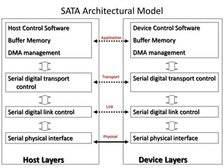
This document discusses the history and technical details of Serial ATA (SATA) storage interfaces. It covers: - The evolution of parallel ATA standards over time and their limitations that led to SATA. - The key benefits of SATA including smaller connectors, higher speeds, and support for multiple devices via point-to-point connections. - An overview of the SATA architecture and protocol stack, including the physical, link, and transport layers. - Details of the physical layer such as connectors, cabling, and out-of-band signaling. - How the link layer implements 8b/10b encoding, scrambling, frame structure, and flow control primitives.


![[Deck] What's New in Spark-Iceberg Integration via DSV2.pptx](https://cdn.slidesharecdn.com/ss_thumbnails/deckwhatsnewinspark-icebergintegrationviadsv2-260210005337-25955b12-thumbnail.jpg?width=640&height=640&fit=bounds)