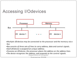
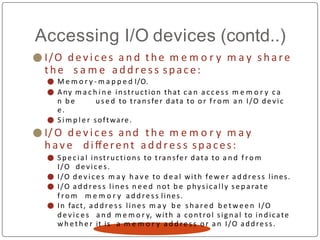
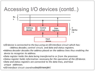
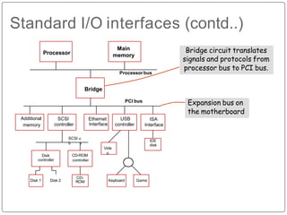
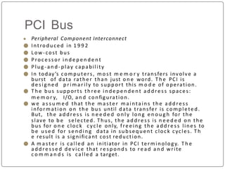
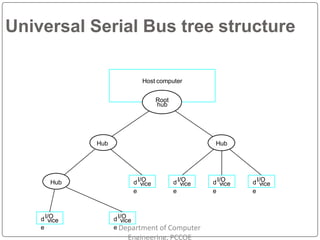
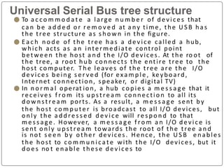
INPUT/OUTPUT ORGANIZATION
Department of Computer
Engineering, PCCOE
Accessing I/Odevices
Bus
I/O device 1 I/O device n
Processor
Department of Computer
Engineering, PCCOE
Memory
•Multiple I/O devices may be connected to the processor and the memory via a
bus.
•Bus consists of three sets of lines to carry address, data and control signals.
•Each I/O device is assigned an unique address.
•To access an I/O device, the processor places the address on the address lines.
•The device recognizes the address, and responds to the control signals.
Accessing I/O devices (contd..)
⚫ I/O dev i c es a n d the m e m o r y m a y sha re
the s a m e a ddress space:
⚫ M e m o r y - m a p p e d I/O.
⚫ Any m a c h i n e instruction that c a n a c c e s s m e m o r y c a
n b e u s e d to transfer data to o r f r o m a n I/O devic
e.
⚫ S i m p l e r software.
⚫ I/ O d ev i ces and the m e m o r y m a y
h av e different a ddress spaces:
⚫ Spe c ia l instructions to transfer data to a n d f r o m
I/O devices.
⚫ I/O d e v i c e s m a y h av e to de al with fewe r a d d re ss lines.
⚫ I/O a d d re s s lines n e e d not b e physically se parate
f r o m m e m o r y a d d re s s lines.
⚫ In fact, a d d re s s lines m a y b e s h a re d b e t we e n I/O
d e v ic e s a n d m e m o r y, with a control signal to indicate
w h et h e r it is a m e m o r y a d d re s s o r a n I/O address.
Accessing I/O devices (contd..)
I/
O
i n
erfac
t e
Address
decoder
Data
registers
Control
circuit
Input
device
Bu
s
•I/O device is connected to the bus using an I/O interface circuit which has:
- Address decoder, control circuit, and data and status registers.
•Address decoder decodes the address placed on the address lines thus enabling the
device to recognize its address.
•Data register holds the data being transferred to or from the processor.
•Status register holds information necessary for the operation of the I/O device.
•Data and status registers are connected to the data lines, and have
unique addresses.
•I/O interface circuit coordinat
D
ee
sp
I/
a
O
rtt
m
ra
en
ns
tfo
ef
rs
C
Accessing I/O devices (contd..)
Department of Computer
Engineering, PCCOE
⚫ Rec a ll t hat t h e r a t e o f t r a n s fe r to a n d f r o m I/O
d e v i c e s is s l o w e r t h a n t h e s p e e d of t h e
p r o c e s s o r. T h i s c r e a t e s t h e n e e d f o r
m e c h a n i s m s to s y n c h r o n i z e d a t a t ra n s fe r s
b e t w e e n t h e m .
⚫ P r o g r a m - c o n t r o l l e d I/O:
⚫ Pro cessor re peat edly monitors a status flag to
achieve the necessary synchronization.
⚫ Processor polls the I/O device.
⚫ Two o t h e r m e c h a n i s m s u s e d f o r
s y n c h r o n i z i n g d a t a t ra n sfe rs b e t w e e n t h e
p r o c e s s o r a n d m e m o r y :
⚫ Interrupts.
⚫ Direct M e m o r y Access.
Bus arbitration
Engineering, PCCOE
⚫ Processor a n d DMA controllers both
n e e d to initiate data transfers o n the
bus a n d a cc ess m a i n m e m o r y.
⚫ T h e d ev i c e that is allowed to initiate
transfers o n the bus at a ny given t i m e
is called thebus master.
⚫ W h e n the current m a ste r
relinquishes its status
master, another d ev ic e
bus
as the bus
ca n acquire
this status.
⚫ T h e p ro c e s s b y w h ic h the next d e v i c e to b e c o m e the
bus m a s te r is sele cte d a n d bus m a ste rsh i p is
transferred to it is called bus arbitration.
⚫ Centralize d arbitration:
⚫ A single bus arbiter p e r fo r m s the arbitration.
⚫ Distributed arbitration:
⚫ All d e v ic e s particD
ip
ep
aa
tr
e
tm
in
ent
th
oe
f Cs
oe
m
lp
eu
ctte
ir
on of the n ext bus
Interface Circuits
Department of Computer
Engineering, PCCOE
Interface circuits
Department of Computer
Engineering, PCCOE
⚫ I/O interface consists of the circuitry required
to conne ct a n I/O de v ic e to a c o m p u te r bus.
⚫ S ide of the interfa ce whic h connects to
the c o m p u te r has bus signals for:
⚫ Address,
⚫ Data
⚫ Control
⚫ S ide of the interfa ce whic h connects to the
I/O de v ic e has:
⚫ Data pat h a n d associated co nt ro ls to tra nsfe r data bet ween
the inte rfa ce a n d the I/O device.
⚫ This side is called as a “port”.
⚫ Ports ca n be classified into two:
⚫ Parallel port,
⚫ Serial port.
Interface circuits (contd..)
Department of Computer
Engineering, PCCOE
⚫ Paral lel port tra nsfe rs data in the fo r m of
a n u m b e r of bits, n o r m a l l y 8 or 16 to or
f r o m the device.
⚫ Serial port transfers a n d recei ves data
o n e bit at a time.
⚫ Processor c o m m u n i c a t e s wi th the bus
in the s a m e way, wh et her it is a
parallel port or a serial port.
⚫ Co nve rsion f r o m the parallel to serial a n d v ic e ve rs
a takes plac e inside the interface circuit.
Parallel port
Valid
Data
Keyboard
Encod
er and
debug
er
circuit
SI
N
Inpu
intterfa
ce
DATAIN
Processor
Dat
a
Address
R / W
Master-read
Slave-read
- Slave-ready signal.
•Keyboard is connected to a processor using a parallel port.
•Processor is 32-bits and uses memory-mapped I/O and the
asynchronous bus protocol.
•On the processor side of the interface we have:
- Data lines.
- Address lines
- Control or R/W line.
- Master-ready signal and
Serial port
⚫ Serial port
processor
is u sed to connect the
to I/O devi ces that require
transmission of data o n e bit at a time.
⚫ Serial port c o m m u n i c a t e s in a bit-
serial fa shion on the d ev i c e side and
bit parallel fashion o n the bus side.
⚫ Transformation b e t we e n the parallel a n d serial
formats is a c h ieve d with shift registers that h av e
para llel a c c e s s
capability.
Serial port (contd..)
⚫ Serial interfaces require fewer wires, a n d
h e n c e serial transmission is convenient for
connecting devi ces that a re physically
distant f r o m the computer.
⚫ S p e e dof transmission of the data over a
serial interfa ce is k nown as the “bit rate”.
⚫ Bit rate d e p e n d s o n the nature of the d ev ic e s connected.
⚫ In o rd e r to a c c o m m o d a t e dev ic es wi th a
ra n g e of speeds, a serial interface m u st b e
able to u s e a ra n g e of clock speeds.
⚫ S evera l standard serial interfaces h av e b e e n
developed:
⚫ Universal Asyn ch ro nous Re ce ive r Transmitter (UART) for l ow -
sp e e d serial devices.
Standard I/O interfaces
⚫ I/O d e vic e is conn e c te d to a c o m p u te r using
a n interfa ce circuit.
⚫ Do we h ave to design a diffe rent interfa ce for
e v e r y combination of a n I/O de v ic e a n d a
computer?
⚫ A practical a p p roa c h is to deve lop standard
int erfa ces a n d protocols.
⚫ A personal c o m p u te r has:
⚫ A m o t h e r bo a rd which h o u se s t he proces sor chip, m a i n
m e m o r y a n d s o m e I/O interfaces.
⚫ A few conne ctors into w hi ch additional interfaces can b e
plugged.
⚫ Processor bus is d e fi n e d by the signals o n the
p roce ssor chip.
⚫ Devic es w hich require h i g h - s p e e d connection to the proces sor
Standard I/O interfaces (contd..)
⚫ A n u m b e r of standards h av e
b e e n d eve l o p ed for the
ex pa nsi o n bus.
⚫ S o m e h a v e e vo l ve d by default.
⚫ For e xa m p l e , IBM’s Industry Stan dard
Architecture.
⚫ T h re e widely u s e d bus standards:
⚫ PCI (Peripheral C o m p o n e n t Interconnect)
⚫ SC SI (Small C o m p u te r S y s t e m Interface)
⚫ U S B (Universal Serial Bus)
Standard I/O interfaces (contd..)
Main
memory
Processor
Bridge
Processor bus
PCI bus
Additional
memory
CD-ROM
controller
Disk
controller
Disk 1 Disk 2
CD-
ROM
SCSI
controller
USB
controller
Vide
o
Keyboard Game
IDE
disk
SCSI u
b s
Ethernet
Interface
Expansion bus on
the motherboard
Bridge circuit translates
signals and protocols from
processor bus to PCI bus.
ISA
Interface
PCI Bus
● Peripheral Component Interconnect
⚫ Introduced in 1 9 9 2
⚫ Low-cost bus
⚫ Proc e ssor i n d e p e n d e n t
⚫ Plu g - a n d - play capability
⚫ In today’s com pu ters, m o s t m e m o r y transfers involve a
burst of data rather than just o n e word. T h e PCI is
d e s i g n e d p r im a r i l y to support this m o d e of operation.
⚫ T h e bus supports th ree i n d e p e n d e n t a d d re s s spaces:
m e m o r y, I/O, a n d configuration.
⚫ w e a s s u m e d that the m a s te r mainta in s th e a d d re s s
information o n the bus until data transfer is comp lete d.
But, the a d d re s s is n e e d e d o n l y long e n o u g h for the
slave to b e selected. Thus, the a d d re s s is n e e d e d o n the
bus for o n e clock cycle only, free ing the a d d re s s lines to
b e u se d for s e n d in g data in subsequent clock cycles. T h
e result is a significant cost reduction.
⚫ A m a ste r is called a n initiator in PCI terminology. T h e
a d d re s s e d d e v i c e that re s p o n d s to re a d a n d write
c o m m a n d s is called a target.
SCSIBus
Department of Computer
Engineering, PCCOE
⚫ T h e a c r o n y m SCSI stands for S m a l l C o m p u te r
S y s t e m Inte rfa ce.
⚫ It refers to a standard bus d e fi n e d by the
A m e r i ca n National Standards Institute (ANSI)
⚫ In the original specifications of the standard,
devic es such as disks a re conn e c te d to a
c o m p u te r via a 5 0 - w i re cable, whic h ca n b e
up to 2 5 m e te rs in length a n d ca n transfer
data at rates up to 5 megabytes/s.
⚫ T h e SCSI bus standard has u n d e rgo n e m a n y
revisions, a n d its data transfer capability
has inc re ase d v e r y rapidly, almost doubling
e v e r y two years.
⚫ S C S I - 2 a n d S C S I - 3 h ave b e e n define d,
a n d e a c h has several options.
SCSI Bus(Contd.,)
Department of Computer
Engineering, PCCOE
⚫ D evic es co n n e c te d to the SC SI bus a re not part of the a d d re s s
s p a c e of the p ro c e s so r
⚫ T h e S C S I b u s is c o n n e c t e d to t h e p r o c e s s o r bus t h ro u g h a S C S
I controller. T h i s co nt ro l l e r u s e s DMA to t ra n s fe r d a ta p a cke ts f r o
m the m a i n m e m o r y to the device, or v i c e vers a.
⚫ A p a c ke t m a y c o n ta i n a b l o c k of data, c o m m a n d s f r o m t h
e p ro c e s sor to the device, o r status information about the device.
⚫ A co n t ro l l e r c o n n e c t e d to a S C S I bus is o n e of two t y p e s – an
in itiator or a target.
⚫ An in i t iator h a s t h e ability to s e l e c t a p a r t i cu l a r ta rget a n d to s e n d
c o m m a n d s s p e c i f y i n g t h e o p e ra t i o n s to be p e r f o r m e d . T h e d i s k
co n t ro l l e r o p e ra t e s as a target. It c a r r i e s out t h e c o m m a n d s
it re c e ive s f r o m the initiator.
⚫ T h e in i t iator e s ta b l i s h e s a l o g i ca l c o n n e c t i o n with t h e i n t e n d e
d target.
⚫ O n c e this conn ec tion h a s b e e n established, it c a n b e s u s p e n d e d
a n d re store d as needed to tra nsfe r c o m m a n d s a n d bursts of data.
⚫ W h i l e a particular con ne ction is suspe nd e d, other d ev ic e c a n u s e
the bus to tra nsfe r info rmation.
⚫ This ability to ove rla p data transfer requests is o n e of the ke y
features of the SCSI bus that le ad s to its h ig h p e r fo rm a n c e .
SCSI Bus(Contd.,)
Department of Computer
Engineering, PCCOE
⚫ Data transfers o n the SCSI bus a re
always controlled b y the target
controller.
⚫ To s e n d a c o m m a n d to a target, an
initiator requests control of the bus and,
after winning arbitration, selects the
controller it
a n d h a n d s
wants to c o m m u n i c a t e with
co nt ro l of the bus over to it.
⚫ T h e n the controller starts a data
tra nsfe r opera tion to rec ei ve a
c o m m a n d f r o m the initiator.
USB
Department of Computer
Engineering, PCCOE
⚫ Universal Serial Bus (USB) is a n industry
standard d eve l o p e d through a
collaborative effort of several co m p u t e r
a n d co m m u n i c a t i o ncompa ni es,
including C o m p a q , Hewlett-Packard,
Intel, Lucent , Microsoft, Nortel
Net wor ks, and Philips.
⚫ S p e e d
⚫ Low-speed(1.5 Mb/s)
⚫ Full-speed(12 Mb/s)
⚫ High-speed(480 Mb/s)
⚫ Port Limitation
⚫ Dev ice Characteristics
⚫ Plug - a nd- play
Host computer
Root
hub
Hub
dI/O
vice
Hub dI/O
e
vice
dI/O
vice
Hub
dI/O
e
vice dI/O
e
vice
dI/O
e
vice
Universal Serial Bus tree structure
e e Department of Computer
Engineering, PCCOE
Universal Serial Bus tree structure
⚫ To a c c o m m o d a t e a large n u m b e r of devi ce s that
ca n b e a d d e d o r r e m o v e d at a ny time, the U S B ha s
the tree structure as s ho w n in the figure.
⚫ E a c h n o d e of the tree ha s a d e v i c e called a hub,
which acts as a n intermediate control point
betwe en the host a n d the I/O devices. At the ro ot of
the tree, a root hub co nnects the entire tree to the
host computer. T h e leaves of the tree are the I/O
de vice s being s e r ve d (for exa m p l e , keyboard,
Internet connection, speaker, o r digital TV)
⚫ In n o r m a l operat ion, a hub copies a m e s s a g e that it
receives f ro m its u pst re a m co nnectio n to all its
d o w n st re a m ports. As a result, a m e s s a g e sent by
the host co m p u t e r is broadcast to all I/O devices, but
o nly the a d d re s s e d d e v i c e will re s p o n d to that
m e s s a ge . However, a m e s s a g e f ro m a n I/O d e v i c e is
sent o nly u pst re a m towards the root of the tree a n d
is not s e e n by other devices. Hence, the U S B enables
the host to c o m m u n i c a t e with the I/O devices, but it
d o e s no t enable these d evi ce s to

Unit 4 Part2-Input-output Subsystem.pptx

  • 1.
    INPUT/OUTPUT ORGANIZATION Department ofComputer Engineering, PCCOE
  • 2.
    Accessing I/Odevices Bus I/O device1 I/O device n Processor Department of Computer Engineering, PCCOE Memory •Multiple I/O devices may be connected to the processor and the memory via a bus. •Bus consists of three sets of lines to carry address, data and control signals. •Each I/O device is assigned an unique address. •To access an I/O device, the processor places the address on the address lines. •The device recognizes the address, and responds to the control signals.
  • 3.
    Accessing I/O devices(contd..) ⚫ I/O dev i c es a n d the m e m o r y m a y sha re the s a m e a ddress space: ⚫ M e m o r y - m a p p e d I/O. ⚫ Any m a c h i n e instruction that c a n a c c e s s m e m o r y c a n b e u s e d to transfer data to o r f r o m a n I/O devic e. ⚫ S i m p l e r software. ⚫ I/ O d ev i ces and the m e m o r y m a y h av e different a ddress spaces: ⚫ Spe c ia l instructions to transfer data to a n d f r o m I/O devices. ⚫ I/O d e v i c e s m a y h av e to de al with fewe r a d d re ss lines. ⚫ I/O a d d re s s lines n e e d not b e physically se parate f r o m m e m o r y a d d re s s lines. ⚫ In fact, a d d re s s lines m a y b e s h a re d b e t we e n I/O d e v ic e s a n d m e m o r y, with a control signal to indicate w h et h e r it is a m e m o r y a d d re s s o r a n I/O address.
  • 4.
    Accessing I/O devices(contd..) I/ O i n erfac t e Address decoder Data registers Control circuit Input device Bu s •I/O device is connected to the bus using an I/O interface circuit which has: - Address decoder, control circuit, and data and status registers. •Address decoder decodes the address placed on the address lines thus enabling the device to recognize its address. •Data register holds the data being transferred to or from the processor. •Status register holds information necessary for the operation of the I/O device. •Data and status registers are connected to the data lines, and have unique addresses. •I/O interface circuit coordinat D ee sp I/ a O rtt m ra en ns tfo ef rs C
  • 5.
    Accessing I/O devices(contd..) Department of Computer Engineering, PCCOE ⚫ Rec a ll t hat t h e r a t e o f t r a n s fe r to a n d f r o m I/O d e v i c e s is s l o w e r t h a n t h e s p e e d of t h e p r o c e s s o r. T h i s c r e a t e s t h e n e e d f o r m e c h a n i s m s to s y n c h r o n i z e d a t a t ra n s fe r s b e t w e e n t h e m . ⚫ P r o g r a m - c o n t r o l l e d I/O: ⚫ Pro cessor re peat edly monitors a status flag to achieve the necessary synchronization. ⚫ Processor polls the I/O device. ⚫ Two o t h e r m e c h a n i s m s u s e d f o r s y n c h r o n i z i n g d a t a t ra n sfe rs b e t w e e n t h e p r o c e s s o r a n d m e m o r y : ⚫ Interrupts. ⚫ Direct M e m o r y Access.
  • 6.
    Bus arbitration Engineering, PCCOE ⚫Processor a n d DMA controllers both n e e d to initiate data transfers o n the bus a n d a cc ess m a i n m e m o r y. ⚫ T h e d ev i c e that is allowed to initiate transfers o n the bus at a ny given t i m e is called thebus master. ⚫ W h e n the current m a ste r relinquishes its status master, another d ev ic e bus as the bus ca n acquire this status. ⚫ T h e p ro c e s s b y w h ic h the next d e v i c e to b e c o m e the bus m a s te r is sele cte d a n d bus m a ste rsh i p is transferred to it is called bus arbitration. ⚫ Centralize d arbitration: ⚫ A single bus arbiter p e r fo r m s the arbitration. ⚫ Distributed arbitration: ⚫ All d e v ic e s particD ip ep aa tr e tm in ent th oe f Cs oe m lp eu ctte ir on of the n ext bus
  • 7.
    Interface Circuits Department ofComputer Engineering, PCCOE
  • 8.
    Interface circuits Department ofComputer Engineering, PCCOE ⚫ I/O interface consists of the circuitry required to conne ct a n I/O de v ic e to a c o m p u te r bus. ⚫ S ide of the interfa ce whic h connects to the c o m p u te r has bus signals for: ⚫ Address, ⚫ Data ⚫ Control ⚫ S ide of the interfa ce whic h connects to the I/O de v ic e has: ⚫ Data pat h a n d associated co nt ro ls to tra nsfe r data bet ween the inte rfa ce a n d the I/O device. ⚫ This side is called as a “port”. ⚫ Ports ca n be classified into two: ⚫ Parallel port, ⚫ Serial port.
  • 9.
    Interface circuits (contd..) Departmentof Computer Engineering, PCCOE ⚫ Paral lel port tra nsfe rs data in the fo r m of a n u m b e r of bits, n o r m a l l y 8 or 16 to or f r o m the device. ⚫ Serial port transfers a n d recei ves data o n e bit at a time. ⚫ Processor c o m m u n i c a t e s wi th the bus in the s a m e way, wh et her it is a parallel port or a serial port. ⚫ Co nve rsion f r o m the parallel to serial a n d v ic e ve rs a takes plac e inside the interface circuit.
  • 10.
    Parallel port Valid Data Keyboard Encod er and debug er circuit SI N Inpu intterfa ce DATAIN Processor Dat a Address R/ W Master-read Slave-read - Slave-ready signal. •Keyboard is connected to a processor using a parallel port. •Processor is 32-bits and uses memory-mapped I/O and the asynchronous bus protocol. •On the processor side of the interface we have: - Data lines. - Address lines - Control or R/W line. - Master-ready signal and
  • 11.
    Serial port ⚫ Serialport processor is u sed to connect the to I/O devi ces that require transmission of data o n e bit at a time. ⚫ Serial port c o m m u n i c a t e s in a bit- serial fa shion on the d ev i c e side and bit parallel fashion o n the bus side. ⚫ Transformation b e t we e n the parallel a n d serial formats is a c h ieve d with shift registers that h av e para llel a c c e s s capability.
  • 12.
    Serial port (contd..) ⚫Serial interfaces require fewer wires, a n d h e n c e serial transmission is convenient for connecting devi ces that a re physically distant f r o m the computer. ⚫ S p e e dof transmission of the data over a serial interfa ce is k nown as the “bit rate”. ⚫ Bit rate d e p e n d s o n the nature of the d ev ic e s connected. ⚫ In o rd e r to a c c o m m o d a t e dev ic es wi th a ra n g e of speeds, a serial interface m u st b e able to u s e a ra n g e of clock speeds. ⚫ S evera l standard serial interfaces h av e b e e n developed: ⚫ Universal Asyn ch ro nous Re ce ive r Transmitter (UART) for l ow - sp e e d serial devices.
  • 13.
    Standard I/O interfaces ⚫I/O d e vic e is conn e c te d to a c o m p u te r using a n interfa ce circuit. ⚫ Do we h ave to design a diffe rent interfa ce for e v e r y combination of a n I/O de v ic e a n d a computer? ⚫ A practical a p p roa c h is to deve lop standard int erfa ces a n d protocols. ⚫ A personal c o m p u te r has: ⚫ A m o t h e r bo a rd which h o u se s t he proces sor chip, m a i n m e m o r y a n d s o m e I/O interfaces. ⚫ A few conne ctors into w hi ch additional interfaces can b e plugged. ⚫ Processor bus is d e fi n e d by the signals o n the p roce ssor chip. ⚫ Devic es w hich require h i g h - s p e e d connection to the proces sor
  • 14.
    Standard I/O interfaces(contd..) ⚫ A n u m b e r of standards h av e b e e n d eve l o p ed for the ex pa nsi o n bus. ⚫ S o m e h a v e e vo l ve d by default. ⚫ For e xa m p l e , IBM’s Industry Stan dard Architecture. ⚫ T h re e widely u s e d bus standards: ⚫ PCI (Peripheral C o m p o n e n t Interconnect) ⚫ SC SI (Small C o m p u te r S y s t e m Interface) ⚫ U S B (Universal Serial Bus)
  • 15.
    Standard I/O interfaces(contd..) Main memory Processor Bridge Processor bus PCI bus Additional memory CD-ROM controller Disk controller Disk 1 Disk 2 CD- ROM SCSI controller USB controller Vide o Keyboard Game IDE disk SCSI u b s Ethernet Interface Expansion bus on the motherboard Bridge circuit translates signals and protocols from processor bus to PCI bus. ISA Interface
  • 16.
    PCI Bus ● PeripheralComponent Interconnect ⚫ Introduced in 1 9 9 2 ⚫ Low-cost bus ⚫ Proc e ssor i n d e p e n d e n t ⚫ Plu g - a n d - play capability ⚫ In today’s com pu ters, m o s t m e m o r y transfers involve a burst of data rather than just o n e word. T h e PCI is d e s i g n e d p r im a r i l y to support this m o d e of operation. ⚫ T h e bus supports th ree i n d e p e n d e n t a d d re s s spaces: m e m o r y, I/O, a n d configuration. ⚫ w e a s s u m e d that the m a s te r mainta in s th e a d d re s s information o n the bus until data transfer is comp lete d. But, the a d d re s s is n e e d e d o n l y long e n o u g h for the slave to b e selected. Thus, the a d d re s s is n e e d e d o n the bus for o n e clock cycle only, free ing the a d d re s s lines to b e u se d for s e n d in g data in subsequent clock cycles. T h e result is a significant cost reduction. ⚫ A m a ste r is called a n initiator in PCI terminology. T h e a d d re s s e d d e v i c e that re s p o n d s to re a d a n d write c o m m a n d s is called a target.
  • 17.
    SCSIBus Department of Computer Engineering,PCCOE ⚫ T h e a c r o n y m SCSI stands for S m a l l C o m p u te r S y s t e m Inte rfa ce. ⚫ It refers to a standard bus d e fi n e d by the A m e r i ca n National Standards Institute (ANSI) ⚫ In the original specifications of the standard, devic es such as disks a re conn e c te d to a c o m p u te r via a 5 0 - w i re cable, whic h ca n b e up to 2 5 m e te rs in length a n d ca n transfer data at rates up to 5 megabytes/s. ⚫ T h e SCSI bus standard has u n d e rgo n e m a n y revisions, a n d its data transfer capability has inc re ase d v e r y rapidly, almost doubling e v e r y two years. ⚫ S C S I - 2 a n d S C S I - 3 h ave b e e n define d, a n d e a c h has several options.
  • 18.
    SCSI Bus(Contd.,) Department ofComputer Engineering, PCCOE ⚫ D evic es co n n e c te d to the SC SI bus a re not part of the a d d re s s s p a c e of the p ro c e s so r ⚫ T h e S C S I b u s is c o n n e c t e d to t h e p r o c e s s o r bus t h ro u g h a S C S I controller. T h i s co nt ro l l e r u s e s DMA to t ra n s fe r d a ta p a cke ts f r o m the m a i n m e m o r y to the device, or v i c e vers a. ⚫ A p a c ke t m a y c o n ta i n a b l o c k of data, c o m m a n d s f r o m t h e p ro c e s sor to the device, o r status information about the device. ⚫ A co n t ro l l e r c o n n e c t e d to a S C S I bus is o n e of two t y p e s – an in itiator or a target. ⚫ An in i t iator h a s t h e ability to s e l e c t a p a r t i cu l a r ta rget a n d to s e n d c o m m a n d s s p e c i f y i n g t h e o p e ra t i o n s to be p e r f o r m e d . T h e d i s k co n t ro l l e r o p e ra t e s as a target. It c a r r i e s out t h e c o m m a n d s it re c e ive s f r o m the initiator. ⚫ T h e in i t iator e s ta b l i s h e s a l o g i ca l c o n n e c t i o n with t h e i n t e n d e d target. ⚫ O n c e this conn ec tion h a s b e e n established, it c a n b e s u s p e n d e d a n d re store d as needed to tra nsfe r c o m m a n d s a n d bursts of data. ⚫ W h i l e a particular con ne ction is suspe nd e d, other d ev ic e c a n u s e the bus to tra nsfe r info rmation. ⚫ This ability to ove rla p data transfer requests is o n e of the ke y features of the SCSI bus that le ad s to its h ig h p e r fo rm a n c e .
  • 19.
    SCSI Bus(Contd.,) Department ofComputer Engineering, PCCOE ⚫ Data transfers o n the SCSI bus a re always controlled b y the target controller. ⚫ To s e n d a c o m m a n d to a target, an initiator requests control of the bus and, after winning arbitration, selects the controller it a n d h a n d s wants to c o m m u n i c a t e with co nt ro l of the bus over to it. ⚫ T h e n the controller starts a data tra nsfe r opera tion to rec ei ve a c o m m a n d f r o m the initiator.
  • 20.
    USB Department of Computer Engineering,PCCOE ⚫ Universal Serial Bus (USB) is a n industry standard d eve l o p e d through a collaborative effort of several co m p u t e r a n d co m m u n i c a t i o ncompa ni es, including C o m p a q , Hewlett-Packard, Intel, Lucent , Microsoft, Nortel Net wor ks, and Philips. ⚫ S p e e d ⚫ Low-speed(1.5 Mb/s) ⚫ Full-speed(12 Mb/s) ⚫ High-speed(480 Mb/s) ⚫ Port Limitation ⚫ Dev ice Characteristics ⚫ Plug - a nd- play
  • 21.
    Host computer Root hub Hub dI/O vice Hub dI/O e vice dI/O vice Hub dI/O e vicedI/O e vice dI/O e vice Universal Serial Bus tree structure e e Department of Computer Engineering, PCCOE
  • 22.
    Universal Serial Bustree structure ⚫ To a c c o m m o d a t e a large n u m b e r of devi ce s that ca n b e a d d e d o r r e m o v e d at a ny time, the U S B ha s the tree structure as s ho w n in the figure. ⚫ E a c h n o d e of the tree ha s a d e v i c e called a hub, which acts as a n intermediate control point betwe en the host a n d the I/O devices. At the ro ot of the tree, a root hub co nnects the entire tree to the host computer. T h e leaves of the tree are the I/O de vice s being s e r ve d (for exa m p l e , keyboard, Internet connection, speaker, o r digital TV) ⚫ In n o r m a l operat ion, a hub copies a m e s s a g e that it receives f ro m its u pst re a m co nnectio n to all its d o w n st re a m ports. As a result, a m e s s a g e sent by the host co m p u t e r is broadcast to all I/O devices, but o nly the a d d re s s e d d e v i c e will re s p o n d to that m e s s a ge . However, a m e s s a g e f ro m a n I/O d e v i c e is sent o nly u pst re a m towards the root of the tree a n d is not s e e n by other devices. Hence, the U S B enables the host to c o m m u n i c a t e with the I/O devices, but it d o e s no t enable these d evi ce s to