Downloaded 372 times

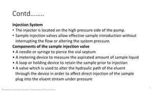
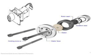
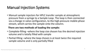
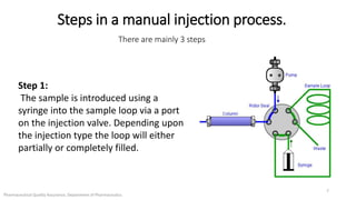
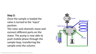

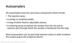
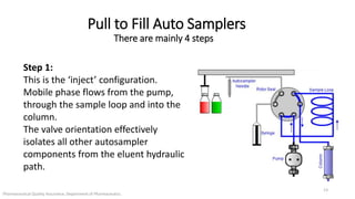
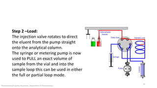
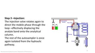
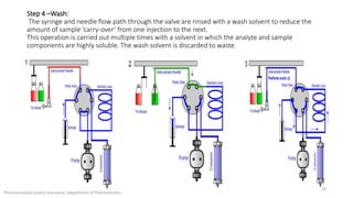
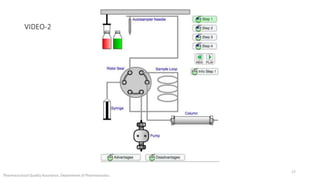
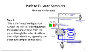
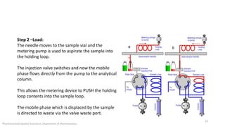
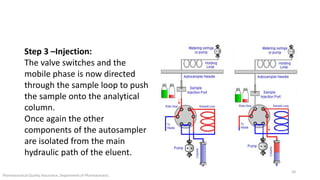
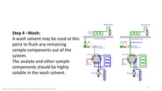
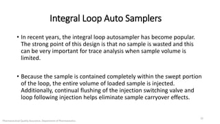

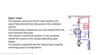
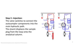


The document discusses sample injection systems used in high performance liquid chromatography (HPLC). It describes the key components of sample injection valves, including a needle or syringe, metering device, sample loop, and valve. It also summarizes different types of injection systems, including manual injection, pull-to-fill autosamplers, push-to-fill autosamplers, and integral-loop autosamplers. Each type follows similar steps of loading the sample, injecting it, and washing the system.


![Interfaces in chromatography [LC-MS, GC-MS, HPTLC, LC, GC]](https://cdn.slidesharecdn.com/ss_thumbnails/34-191218130611-thumbnail.jpg?width=640&height=640&fit=bounds)


