Downloaded 141 times


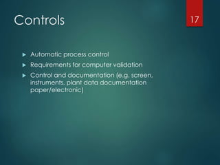
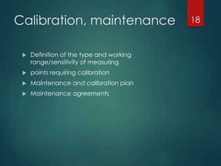
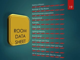
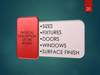


This document outlines the components and requirements of a user requirement specification (URS) for designing new facilities and equipment. A URS ensures that user needs are clearly defined upfront and includes operating requirements, regulatory standards, and specifications that will be used in the design review process. It covers various areas like project description, regulatory requirements, environmental conditions, safety devices, utilities needs, technical specifications, cleaning requirements, performance data, controls, and calibration and maintenance plans. The URS establishes the foundation for design qualification to take place before equipment is constructed so that risks can be identified and addressed early in the design phase.


![ICH guidelines for validation Of Equipments by Nikita Sahu[1].pptx](https://cdn.slidesharecdn.com/ss_thumbnails/ichguidelinesforvalidationofequipmentsbynikitasahu1-231229084118-997cfd59-thumbnail.jpg?width=640&height=640&fit=bounds)


