


![Note: if the pillar is not square, we make w = we in the
formula for σp, where we = 4 Ap / C.
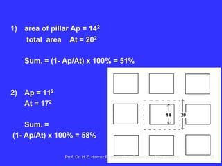
Ap = area of post (perpendicular to the vertical axis) that undergoes axial
loading due to H coverage;
C = outer perimeter of the pillar.
(Ref .: Brady & Brown, chap.13.)
d) Set the width of the gallery B.
e) Sp to determine the load on the pillar for a layer thickness H in the
storage area.
Sp = γ H [ (w+B)/w ] [ (L+B)/w ],
being γ = average specific weight of the cover;
L = length of the column.
f) Select the factor of safety F. Make σp / F = Sp and solve this equation
for w.
The range 1.5 ≤ F ≤ 2.0 is generally used, but each has the formula
recommendation to F to be used.
Prof. Dr. H.Z. Harraz Presentation Room and Pillar method 64](https://image.slidesharecdn.com/3-roomandpillar-141022163816-conversion-gate01/85/Room-and-Pillar-Mining-Method-64-320.jpg)
![g) Check the recovery mining, assuming that the total
thickness of the layer will be mined:
Rec = 1- [ w/(w+B) ] [ L/(L+B) ] .
h) If recovery is not acceptable and needs to be increased,
decreasing w and / or L to meet the goal. Check if the new
combination w and L is acceptable from the point of view
of stability ( F = σp / Sp ).
In Bieniawski formula, F = 1.5 is used for pillars of short duration (panels);
F = 2.0 for long term pillars (axes).
Prof. Dr. H.Z. Harraz Presentation Room and Pillar method 65](https://image.slidesharecdn.com/3-roomandpillar-141022163816-conversion-gate01/85/Room-and-Pillar-Mining-Method-65-320.jpg)
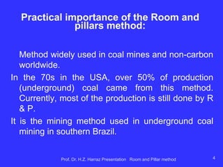
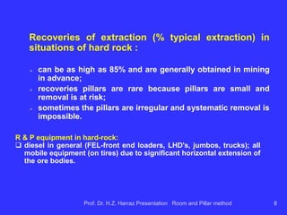
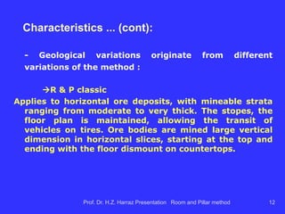
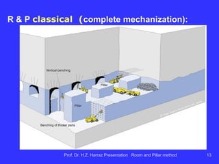
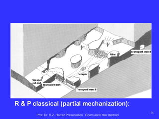
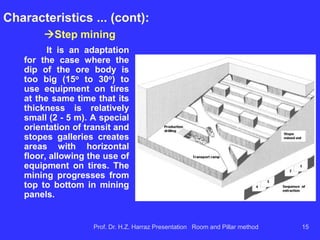
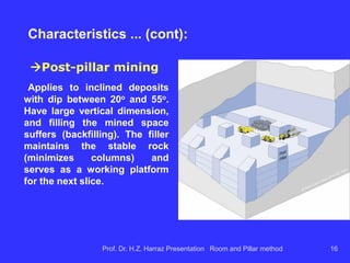
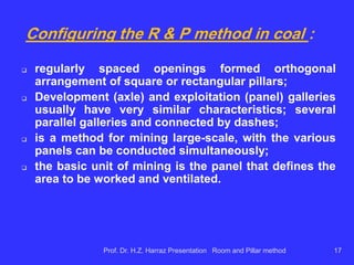
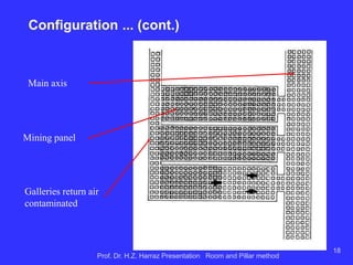
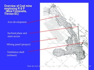
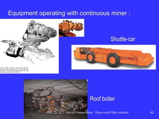
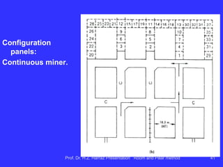
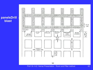
The document discusses the room and pillar (R&P) mining method, which is widely used for mining both coal and non-coal resources. It outlines the practical importance, applications, design parameters, and advantages and disadvantages of this method, including its effectiveness in various geological conditions and the mechanical requirements for extraction. It also provides insights into recovery rates, equipment used, and different configurations applicable to both hard and soft rock environments.


