
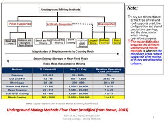
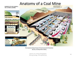
![Overview
Stoping is the process of extracting the desired ore or other mineral from an
underground mine, leaving behind an open space known as a stope.[1]
Stoping is the removal of the orebody from the surrounding rock.
Stoping is used when the country rock is sufficiently strong not to cave into the stope,
although in most cases artificial support is also provided.
The earliest forms of stoping were conducted with hand tools or by fire-setting; later
gunpowder was introduced. From the 19th century onward, various other explosives,
power-tools, and machines came into use. As mining progresses the stope is often
backfilled with tailings, or when needed for strength, a mixture of tailings and cement. In
old mines, stopes frequently collapse at a later time, leaving craters at the surface. They
are an unexpected danger when records of underground mining have been lost with the
passage of time.
Stoping is considered "Productive work", and is contrasted with "Deadwork", the work
required merely to access the mineral deposit, such as sinking shafts and winzes,
carving adits, tunnels, and levels, and establishing ventilation and transportation.[2]
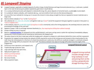
A stope can be created in a variety of ways The specific method of stoping depends
on a number of considerations, both technical and economical, based largely on the
geology of the ore body being mined. These include the incline of the deposit (whether
it is flat, tilted or vertical), the width of the deposit, the grade of the ore, the hardness
and strength of the surrounding rock, and the cost of materials for supports[3] (i.e., The
methods used may vary throughout each mine, depending on the changing
characteristics of the orebody and mine planning techniques).
Prof. Dr. H.Z. Harraz Presentation
Mining Methods
12](https://image.slidesharecdn.com/lecture1-111102174820-phpapp02/85/Lecture-4-Underground-Mining-12-320.jpg)
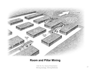
![It is common to dig shafts vertically downwards to reach the ore body and then drive
horizontal levels through it. Stoping then takes place from these levels.
When the ore body is more or less horizontal, various forms of room and pillar
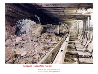
stoping, cut and fill,[4] or longwall mining can take place.
In steeply-dipping ore bodies, such as lodes of tin, the stopes become long narrow
near-vertical spaces, which, if one reaches the surface is known as a Gunnis or
Coffen.[1] A common method of mining such vertical ore bodies is stull stoping.
The development of the infrastructure for the stoping methods is time-consuming,
costly, and complex.
All methods involve:
drilling a pattern of holes into the rock
charging (filling) the holes with explosive
blasting the rock
bogging (digging) it out
transporting it to the surface.
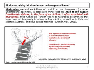
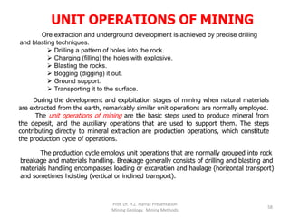
The general approach is to access the orebody at regular intervals (generally
between 15 and 40 vertical meters) and then stope between these.
Rock fill
Orebody
Access
drive
MPI Mines
Overview (Cont.)
Prof. Dr. H.Z. Harraz Presentation
Mining Methods
14](https://image.slidesharecdn.com/lecture1-111102174820-phpapp02/85/Lecture-4-Underground-Mining-14-320.jpg)
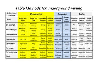
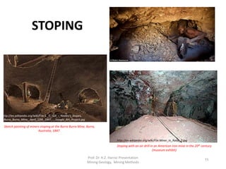
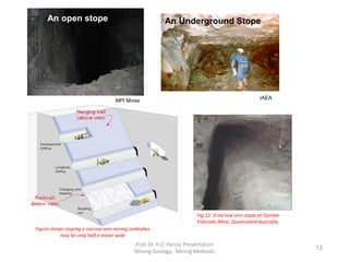
![1) Open-Stope Systems
Open stoping is generally divided into two basic forms based on direction: overhand and underhand
stoping, which refer to the removal of ore from above or below the level, respectively.
It is also possible to combine the two in a single operation.
1.1) Underhand stoping
Underhand stoping, also known as horizontal-cut underhand or underbreaking stoping, is the working of
an ore deposit from the top downwards.
Like shrinkage stoping, underhand stoping is most suitable for steeply dipping ore bodies.[5] Because of
the mechanical advantage it offers hand tools being struck downward (rather than upward, against
gravity), this method was dominant prior to the invention of rock blasting and powered tools.[6]
1.2) Overhand stoping
In overhand stoping, the deposit is worked from the bottom upward, the reverse of underhand stoping.
With the advent of rock blasting and power drills, it became the predominant direction of stoping.[3]
1.3) Combined stoping
In combined stoping, the deposit is simultaneously worked from the bottom upward and the top
downward, combining the techniques of overhand and underhand stoping into a single approach.
1.4) Breast stoping
Breast stoping is a method used in horizontal or near-horizontal ore bodies, where gravity is not
usable to move the ore around.[7]
Breast stoping lacks the characteristic "steps" of either underhand or overhand stoping, being mined in a
singular cut.
Room and pillar is a type of breast stoping.
Prof. Dr. H.Z. Harraz Presentation
Mining Methods
15](https://image.slidesharecdn.com/lecture1-111102174820-phpapp02/85/Lecture-4-Underground-Mining-15-320.jpg)
![3) Cut and Fill (C & F) Stoping
It is one of the more popular methods used for vein deposits and has recently grown in use.
It is an expensive but selective mining method, with low ore loss and dilution.[3] (i.e., allows selective mining
and avoid mining of waste or low grade ore).
Is relatively expensive and therefore is done only in high grade mineralization (Because the method involves
moving fill material as well as a significant amount of drilling and blasting).
It is a method of shorthole mining used in steeply dipping or It is preferred for orebodies with irregular ore
zones and scattered mineralization.
It requires working at face (which is less safe than longhole stoping).
It is used:-
in mining steeply dipping orebodies in stable rock masses (primarily in steeply dipping metal
deposits),
in strata with good to moderate stability, and comparatively high grade mineralization.
either fill option may be consolidated with concrete, or left unconsolidated.
Generally uses no cement
Bottom up mining method: Remove ore in horizontal slices, starting from a bottom undercut and
advancing upward.
Moderate production rates.
Good resource usage.
Not stress friendly.
Moderate ground support
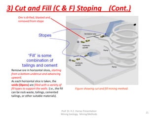
Ore is drilled, blasted and removed from stope.
The ore is mined in slices: As each horizontal or slightly inclined slice is taken, the voids (Opens) are
backfilled with a variety of fill types to support the walls (i.e., the fill can be rock waste, tailings, cemented
tailings, or other suitable materials).
{(note: The fill serves both to support the stope walls and provide a working platform for equipment
when the next slice is mined)}.
Prof. Dr. H.Z. Harraz Presentation
Mining Methods
20](https://image.slidesharecdn.com/lecture1-111102174820-phpapp02/85/Lecture-4-Underground-Mining-20-320.jpg)
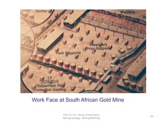
![3) Stull stoping
Stull stoping is a common method of to mine vertical ore bodies or
steeply-dipping ore bodies (because the stopes become long narrow near-
vertical spaces, which, if one reaches the surface is known as a Gunnis or
Coffen[1] ).
Stull stoping is a form of stoping used in hardrock mining that uses
systematic or random timbering ("stulls") placed between the foot and
hangingwall of the vein.
Stull stoping is a supported mining method using timber or rock bolts in
tabular, pitching ore bodies.
It is one of the methods that can be applied to ore bodies that have dips
between 10o and 45o.
The method requires that the hangingwall and often the footwall be of
competent rock as the stulls provide the only artificial support.
It often utilizes artificial pillars of waste to support the roof.
This type of stope has been used up to a depth of 3,500 feet (1,077 m)
and at intervals up to 12 feet (3.7 m) wide.[8]
Prof. Dr. H.Z. Harraz Presentation
Mining Methods
23](https://image.slidesharecdn.com/lecture1-111102174820-phpapp02/85/Lecture-4-Underground-Mining-23-320.jpg)
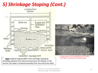
![5) Shrinkage Stoping
Shrinkage stoping may be termed a “classic” mining method, having been perhaps the most popular mining
method for most of the past century. It has largely been replaced by mechanized methods but is still used in many
small mines around the world.
Shrinkage stoping is a short-hole mining method which is most suitable for steeply dipping orebodies (70°- 90°).
Also, the blasted ore must not be affected by storage in the slopes (e.g., sulfide ores have a tendency to oxidize and
decompose when exposed to air).
Its most prominent feature is the use of gravity flow for ore handling: ore from stopes drops directly into rail cars
via chutes obviating manual loading, traditionally the most common and least liked job in mining.
Mining progresses upward (i.e., proceeds from the bottom upwards), with horizontal slices (similar to cut and fill
mining) of ore being blasted along the length of the stope. A portion of the broken ore is allowed to accumulate in
the stope to provide a working plat form for the miners and is there after withdrawn from the stope through
chutes.
The method is similar to cut and fill mining with the exception that after being blasted, broken ore is left in the
stope where it is used to support the surrounding rock and as a platform from which to work.
Because blasted rock takes up a greater volume than in situ rock (due to swell factor), some of the blasted ore
(~40%) must be removed to provide working space for the next ore slice.
Only enough ore is removed from the stope to allow for drilling and blasting the next slice.
Once the top of the stope is reached all the ore is removed from the stope.
The stope is emptied when all of the ore has been blasted.
The stope may be backfilled or left empty, depending on the rock conditions.[10]
Although it is very selective and allows for low dilution, since the most of the ore stays in the stope until mining is
completed there is a delayed return on capital investments.[3]
Shrinkage stoping is more suitable than sublevel stoping for stronger ore and weaker wallrock.
Prof. Dr. H.Z. Harraz Presentation
Mining Methods
26](https://image.slidesharecdn.com/lecture1-111102174820-phpapp02/85/Lecture-4-Underground-Mining-26-320.jpg)

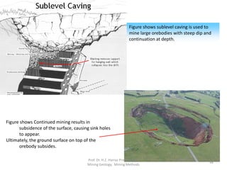
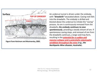
![ An undercut with haulage access is driven under the orebody, with "drawbells"
excavated between the top of the haulage level and the bottom of the undercut. The
drawbells serve as a place for caving rock to fall into.
The orebody is drilled and blasted above the undercut, and the ore is removed via the
haulage access.
Due to the friability of the orebody the ore above the first blast caves and falls into the
drawbells. As ore is removed from the drawbells the orebody caves in providing a
steady stream of ore[3].
If caving stops and removal of ore from the drawbells continues, a large void may form,
resulting in the potential for a sudden and massive collapse and potentially catastrophic
windblast throughout the mine.[4]
Where caving does continue, the ground surface may collapse into a surface depression
(such as those at the Climax and Henderson molybdenum mines in Colorado. Such a
configuration is one of several to which miners apply the term "glory hole“).
Orebodies that do not cave readily are sometimes preconditioned by hydraulic
fracturing, blasting, or by a combination of both. Hydraulic fracturing has been applied
to preconditioning strong roof rock over coal longwall panels, and to inducing caving in
both coal and hard rock mines.
Essentially block caving creates an underground 'inverted open pit'. Surface subsidence
can be a problem….???.
Prof. Dr. H.Z. Harraz Presentation
Mining Methods
50](https://image.slidesharecdn.com/lecture1-111102174820-phpapp02/85/Lecture-4-Underground-Mining-50-320.jpg)
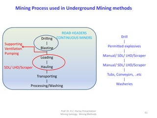
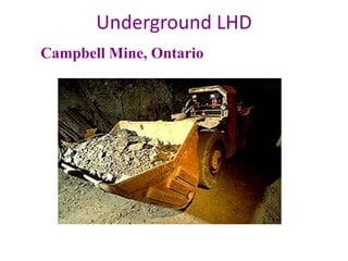
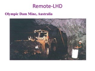
![ In mines which use rubber tired equipment for coarse ore removal, the ore (or
"muck") is removed from the stope (referred to as "mucked out" or "bogged")
using center articulated vehicles (referred to as boggers or LHD [i.e., Load, Haul,
Dump]). These pieces of equipment may operate using diesel or electric engines
and resemble a low-profile front end loader.
In shallower mines , the ore is then dumped into a truck to be hauled to the
surface.
In deeper mines the ore is dumped down an ore pass (a vertical or near vertical
excavation) where it falls to a collection level. On the collection level, it may
receive primary crushing via jaw or cone crusher. The ore is then moved by
conveyor belts, trucks or occasionally trains to the shaft to be hoisted to the
surface in buckets or skips and emptied into bins beneath the surface headframe
for transport to the mill.
In some cases the underground primary crusher feeds an inclined
conveyor belt which delivers ore via an incline shaft direct to the
surface. The ore is fed down ore passes, with mining equipment
accessing the ore body via a decline from surface.
Ore Removal
Prof. Dr. H.Z. Harraz Presentation
Mining Methods
57](https://image.slidesharecdn.com/lecture1-111102174820-phpapp02/85/Lecture-4-Underground-Mining-57-320.jpg)
The document discusses underground mining methods. It begins by explaining that the choice of mining method depends on characteristics of the orebody like thickness and dip, as well as the competency of surrounding rock. It then provides details on various hard rock and soft rock underground mining methods. These include longwall mining, room-and-pillar, blast mining, shortwall mining, and coal skimming for soft rocks. For hard rocks, methods include various stoping techniques, longwall mining, and caving methods. Stoping is defined as the process of extracting ore by leaving behind an open space called a stope.


