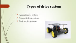
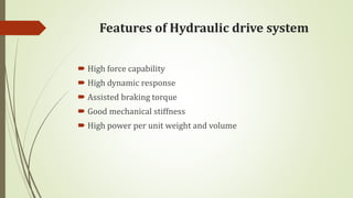
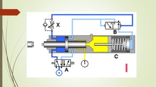
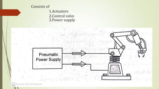
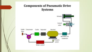
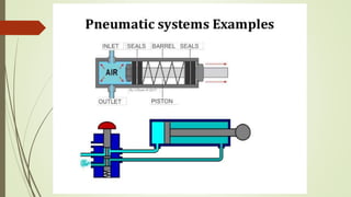
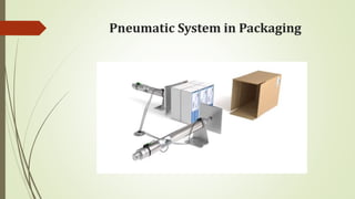
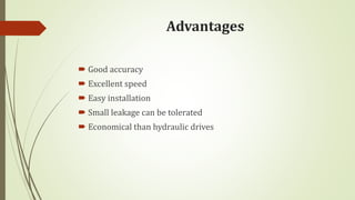
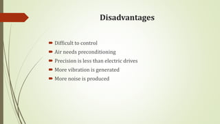
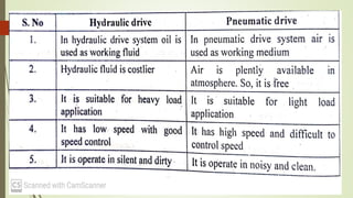
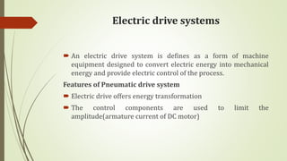
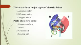
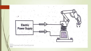
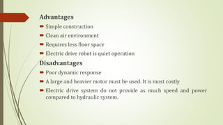
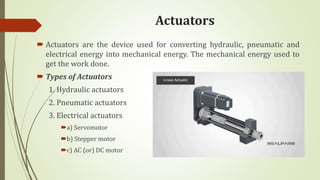
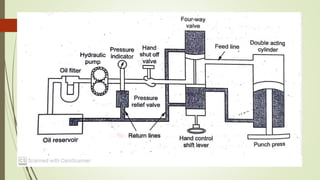
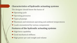
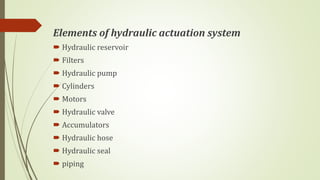
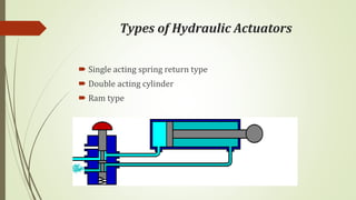
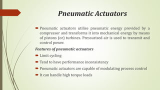
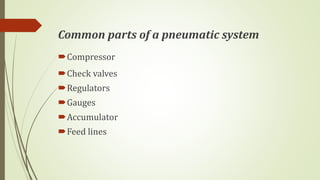
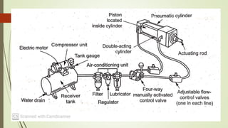
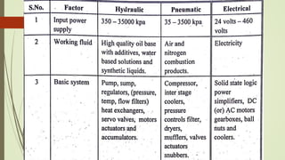
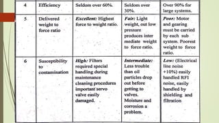
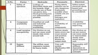
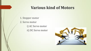
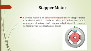
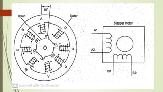
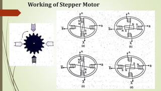
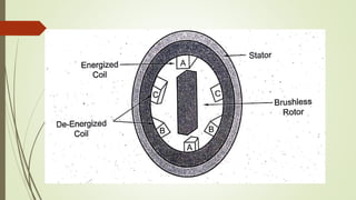
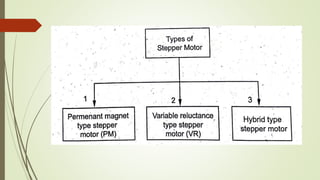
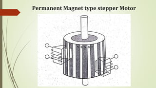
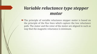
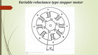
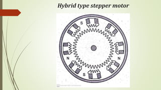
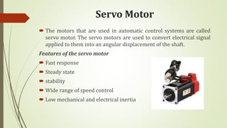
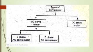
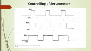
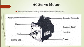
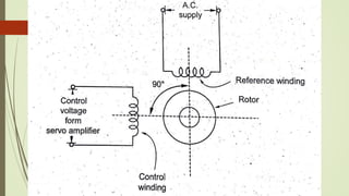
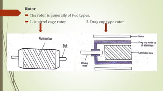
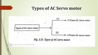
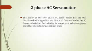
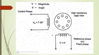
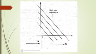
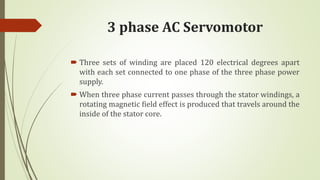
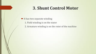
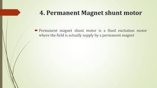
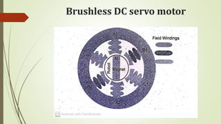
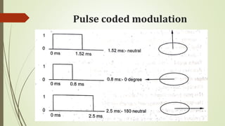
SlideShare a Scribd company logo
ME8099---Robotics
UNIT-2
ROBOT DRIVE SYSTEMS AND END
EFFECTORS
 Pneumatic Drives-Hydraulic Drives-Mechanical Drives-Electrical
Drives-D.C. Servo Motors, Stepper Motors, A.C. Servo Motors-
Salient Features, Applications and Comparison of all these
Drives, End Effectors-Grippers-Mechanical Grippers, Pneumatic
and Hydraulic- Grippers, Magnetic Grippers, Vacuum Grippers;
Two Fingered and Three Fingered Grippers; Internal Grippers
and External Grippers; Selection and Design Considerations.
ROBOT DRIVE SYSTEMS
 Drive means operate the robot.
 The drive system is to provide a means to control the speed and
also torque (or) power.
 Drive system is used for converting hydraulic, pneumatic, and
electrical energy into useful mechanical energy. It is used to
motion transfer and drive the robot.
Types of drive system
 Hydraulic drive systems
 Pneumatic drive systems
 Electric drive systems
Hydraulic drive systems
 Pressurised fluid is used to transmit and control power.
 The hydraulic drive is mostly suitable for heavy load robot
applications
 The term hydraulic refers to the transfer of energy from
pressure difference not from the kinetic energy of flow
Features of Hydraulic drive system
 High force capability
 High dynamic response
 Assisted braking torque
 Good mechanical stiffness
 High power per unit weight and volume
Consists of
1.Actuators
2.Control valve
3.Power supply
Advantages
 No reduction gear is needed
 High accuracy and better response
 Excellent for heavy duty and large robots
 It provide more power than electric drives
Disadvantages
 High maintenance
 More expensive system
 Not suitable for clean air environment
 Requires pump, reservoir, motor and hoses
 More floor space is required
Pneumatic drive systems
 Pressurised air is used to control power.
 With pneumatic valves control the flow of energy from
pressurized gas
Features of Pneumatic drive system
 Compressed air has most of the desired properties and
characteristics of a gas for pneumatic system.
 It is not poisonous and non flammable.
Consists of
1.Actuators
2.Control valve
3.Power supply
Pneumatic System in Packaging
Advantages
 Good accuracy
 Excellent speed
 Easy installation
 Small leakage can be tolerated
 Economical than hydraulic drives
Disadvantages
 Difficult to control
 Air needs preconditioning
 Precision is less than electric drives
 More vibration is generated
 More noise is produced
Electric drive systems
 An electric drive system is defines as a form of machine
equipment designed to convert electric energy into mechanical
energy and provide electric control of the process.
Features of Pneumatic drive system
 Electric drive offers energy transformation
 The control components are used to limit the
amplitude(armature current of DC motor)
There are three major types of electric drives
1. AC servo motor
2. DC servo motor
3. Stepper motor
Parts of electric drive
1. Power modulator
2. Motor
3. Control unit
4. Sensing unit
Advantages
 Simple construction
 Clean air environment
 Requires less floor space
 Electric drive robot is quiet operation
Disadvantages
 Poor dynamic response
 A large and heavier motor must be used. It is most costly
 Electric drive system do not provide as much speed and power
compared to hydraulic system.
Actuators
 Actuators are the device used for converting hydraulic, pneumatic and
electrical energy into mechanical energy. The mechanical energy used to
get the work done.
 Types of Actuators
1. Hydraulic actuators
2. Pneumatic actuators
3. Electrical actuators
a) Servomotor
b) Stepper motor
c) AC (or) DC motor
Hydraulic Actuators
 Hydraulic actuators transform the hydraulic energy stored in a
reservoir into mechanical energy by means of suitable pumps.
 Hydraulic actuators are also fluid power device for industrial
robots which utilise high pressure fluid such as oil to transmit
forces to the point of application desired
Characteristics of hydraulic actuating systems
The designer should know the basics of
 Operating cycle
 Operating pressures
 Types pf pumps
 Maximum and minimum operating and ambient temperatures
 Loads encountered by various components
Features of the hydraulic actuating systems
 High force capability
 Good mechanical stiffness
 High power per unit weight and volume
Elements of hydraulic actuation system
 Hydraulic reservoir
 Filters
 Hydraulic pump
 Cylinders
 Motors
 Hydraulic valve
 Accumulators
 Hydraulic hose
 Hydraulic seal
 piping
Types of Hydraulic Actuators
 Single acting spring return type
 Double acting cylinder
 Ram type
Advantages
 Self lubrication
 No mechanical linkage is required
 It can also provide precise control at low speeds
 Capable of with standing shock loads
 Greater load carrying capacity
Disadvantages
 Expensive
 Noisy operation
 High maintenance
 Not energy sufficient
 Not suitable for clean environment
 Leakage can occur causing a loss in performance
Pneumatic Actuators
 Pneumatic actuators utilise pneumatic energy provided by a
compressor and transforms it into mechanical energy by means
of pistons (or) turbines. Pressurised air is used to transmit and
control power.
Features of pneumatic actuators
 Limit cycling
 Tend to have performance inconsistency
 Pneumatic actuators are capable of modulating process control
 It can handle high torque loads
Common parts of a pneumatic system
Compressor
Check valves
Regulators
Gauges
Accumulator
Feed lines
Advantages
 Control is simple
 It is cheapest form of all actuators
 No mechanical transmission is usually required
 Individual components can be easily interconnected
 Very quick response time and faster cycles
Disadvantages
 More noise and vibration
 Not suitable for heavy loads
 Air compressor is required
Electric Actuators
 An actuator obtaining electrical energy from mechanical system
is called electric actuator
Features of the electric actuators
 High band with provide accurate and fast control
 High maximum force allows high acceleration
Electrical actuators comprise the following
 Drive system
1. AC motor 2. DC motor 3. Stepper motor
 Switching device
a) Mechanical switch 1. Solenoids 2. Relays
b) Solid state switch 1. Diodes 2. Thyristor 3. Transistors
Advantages
 High power conversion efficiency
 They are easily maintained and repaired
 Structural components can be light weight
 No pollution of working environment
Disadvantages
 Compliance and wear problems are causing inaccuracies
 A larger and heavier motor must be used which is costly
 They cannot be used in explosive atmospheres
Applications
 Wide range of industries where positioning is needed
 Automation applications
Various kind of Motors
1. Stepper motor
2. Servo motor
i) AC Servo motor
ii) DC Servo motor
Stepper Motor
 A stepper motor is an electromechanical device. Stepper motor
is a device which transforms electrical pulses into equal
increments of rotary shaft motion called steps. It converts
electrical power into mechanical power.
Working of Stepper Motor
Permanent Magnet type stepper
Motor
 The permanent magnet type stepper motor has a stator. That is
of electromagnet. A rotor that is of permanent magnet.
Therefore this motor is called permanent magnet type stepper
motor.
Permanent Magnet type stepper Motor
Advantages
 A simpler and more reliable
 Field flux is less affected by temperature rise
 Higher efficiency due to the absence of field losses
 Less heating making it is possible to totally enclose the motor
Disadvantages
 Permanent magnets stepper motor cannot produce a high flex density
 Extra ampere-turns cannot be added to reduce the armature reaction
Applications
 Automobiles and air conditioners
 Computer drives
 Electric tooth brushes, portable vacuum cleaners and food mixers
Variable reluctance type stepper
motor
 The principle of variable reluctance stepper motor is based on
the principle of the flux lines which capture the low reluctance
path. The stator and the rotor of the motor are aligned in such as
way that the magnetic reluctance is minimum.
Variable reluctance type stepper motor
Advantages
 High rate of acceleration
 High torque to inertia ratio
 Simple and low cost machine
Disadvantages
 Generally noisy
 There is no winding on rotor
 Lower torque capability
Hybrid type stepper motor
 The hybrid type stepper motor as the name recommends is a
blending of both permanent magnet type stepper motor (PM)
and variable reluctance motor (VR)
Hybrid type stepper motor
Advantages
 It has more torque
 Lower stepping rate
 More efficient at low speeds
 The length of step is smaller
Disadvantages
 Higher inertia
 If the magnetic strength is varied, the performance of the motor is
affected.
 The weight of the motor is more because of the presence of the rotor
magnet.
 Cost is more
Torque vs speed characteristics
Salient features of stepper motor
 Stepper motor is small step angle
 They are high stepping rate and accuracy
 Stepper motor has high positioning accuracy
 A stepper motor is used to achieve precise positioning is a digital
control
 They are ideal for applications requiring quick positioning over a shot
distance
Capabilities of stepper motor
 Precise positioning control
 Finer positioning capabilities
 Low speed with high precision
 Easy control with pulse signals
 Generating high torque with a compact size
Advantages
 Low cost
 High reliability
 High torque at low speeds
 Operates in almost any environment
 Stepper motor is simple to operate
Disadvantages
 lower efficiency
 Low torque to inertia ratio
 Lower power output for their weight and size
 Smooth movement often requires micro stepping
Applications
 Gaming machines
 Textile machinery
 Welding equipment
Servo Motor
 The motors that are used in automatic control systems are called
servo motor. The servo motors are used to convert electrical signal
applied to them into an angular displacement of the shaft.
Features of the servo motor
 Fast response
 Steady state
 stability
 Wide range of speed control
 Low mechanical and electrical inertia
Controlling of Servomotors
Advantages
 Servo motor is small and efficient
 High speed operation is possible
Disadvantages
 Higher cost
 It is not suitable for precision control of rotation
 It is not suitable if we need to prevent vibration
Uses of the servo motor
 The servo motor is built into the camera to correct a lens of the camera to
improve out of focus image
 The servo motor is used in textile to control spinning and weaving
machines
 Used in metal forming and cutting machines to provide specific motion
control for milling machines.
Applications of the servo motor
 Toys
 Cars
 Robotics
 Aeroplanes
 Computers
 Home electronics
 CD/DVD player
AC Servo Motor
 Servo motor is basically consists of stator and rotor
Rotor
 The rotor is generally of two types.
 1. squirrel cage rotor 2. Drag cup type rotor
Types of AC Servo motor
2 phase AC Servomotor
 The stator of the two phase AC servo motor has the two
distributed winding which are displaced from each other by 90
degrees electrical. One winding is known as a reference phase
and other one is known as control phase
3 phase AC Servomotor
 Three sets of winding are placed 120 electrical degrees apart
with each set connected to one phase of the three phase power
supply.
 When three phase current passes through the stator windings, a
rotating magnetic field effect is produced that travels around the
inside of the stator core.
Advantages
 Less maintenance
 High efficiency
 High speed operation is possible
 Resonance and vibration free operation
Disadvantages
 Complex
 Poor motor cooling
 Motor can be damaged by sustained over load
 Most difficult to control in position application
Application
 Robotics
 Machine tools
 Suited for lower power application
DC Servo Motor
 DC servo motor is more (or) less similarly to the normal DC
motor. DC motors are separately excited DC motor (or)
permanent magnet DC motor. They are controlled by armature
voltage. The armature is designed to have large resistance, so
that the torque speed characteristics are linear.
 There fore a step change in the armature voltage results in quick
change in position (or) speed of the motor.
Types of the DC servo Motor
1. Series Motor
 The series motor have a high starting torque and draws large
current
 The speed regulation of this kind of motor is poor
2. Split series Motor
 Split series motor with split field rate with some fractional
kilowatts
 Split series motor has a typical torque speed curve
3. Shunt Control Motor
 It has two separate winding
1. Field winding is on the stator
2. Armature winding is on the rotor of the machine
4. Permanent Magnet shunt motor
 Permanent magnet shunt motor is a fixed excitation motor
where the field is actually supply by a permanent magnet
Brushless DC servo motor
Pulse coded modulation
Torque speed characteristics
Advantages
 Free of vibration and resonance
 High torque to inertia ratio
 High output than from a 50Hz motor of same size
 High efficiency
 Easier speed control from zero speed to full speed in both direction
Disadvantages
 Overload can damage motor
 Has complex architecture and requires encode
 The brush turnout in limited life of 2000 hrs, then service is required
 Motor does not work when something breaks, hence safety circuits are
needed
Robotics - unit-2.ppt

More Related Content

What's hot

Grippers
GrippersGrippers
Grippers
gujjubharat
 
Unit 3 machine vision
Unit 3 machine vision Unit 3 machine vision
Unit 3 machine vision
Dr.G.Saravanan
 
Pick & place robot ppt
Pick & place robot pptPick & place robot ppt
Pick & place robot ppt
Rahul Banerjee
 
Actuators
ActuatorsActuators
Actuators
Anurag Chaudhary
 
Robotics - unit-2 - end effector
Robotics - unit-2 - end effectorRobotics - unit-2 - end effector
Robotics - unit-2 - end effector
rknatarajan
 
ROBOTICS- IMPLEMENTATION AND ROBOT ECONOMICS
ROBOTICS- IMPLEMENTATION AND ROBOT ECONOMICSROBOTICS- IMPLEMENTATION AND ROBOT ECONOMICS
ROBOTICS- IMPLEMENTATION AND ROBOT ECONOMICS
TAMILMECHKIT
 
Robotics and automation _ power sources and sensors
Robotics and automation _  power sources and sensorsRobotics and automation _  power sources and sensors
Robotics and automation _ power sources and sensors
JAIGANESH SEKAR
 
Unit-I Robotics
Unit-I RoboticsUnit-I Robotics
Unit-I Robotics
Muthukumar V
 
ROBOTICS-Me8099 -unit-1.ppT
ROBOTICS-Me8099 -unit-1.ppTROBOTICS-Me8099 -unit-1.ppT
ROBOTICS-Me8099 -unit-1.ppT
dinesh babu
 
Actuators
ActuatorsActuators
selection of robot
selection of robotselection of robot
selection of robot
nabil130290
 
Robotics unit3 sensors
Robotics unit3 sensorsRobotics unit3 sensors
Robotics unit3 sensors
Janarthanan B
 
Low cost automation
Low cost automationLow cost automation
Low cost automation
Ishwar Bhoge
 
Manipulator kinematics
Manipulator kinematicsManipulator kinematics
Manipulator kinematics
Sudhir Reddy
 
04 power transmission systems
04    power transmission systems04    power transmission systems
04 power transmission systems
Ganesh Murugan
 
Robot Configuration - 2
Robot Configuration - 2Robot Configuration - 2
ROBOT DRIVE SYSTEMS AND END EFFECTORS
ROBOT DRIVE SYSTEMS AND END EFFECTORSROBOT DRIVE SYSTEMS AND END EFFECTORS
ROBOT DRIVE SYSTEMS AND END EFFECTORS
TAMILMECHKIT
 
machine and mechanisms
 machine and mechanisms machine and mechanisms
machine and mechanisms
Monu1992
 
Image processing
Image processingImage processing
Image processing
kamal330
 
Antifriction guideways, feed drives, spindles
Antifriction guideways, feed drives, spindlesAntifriction guideways, feed drives, spindles
Antifriction guideways, feed drives, spindles
vedamsh95
 

What's hot (20)

Grippers
GrippersGrippers
Grippers
 
Unit 3 machine vision
Unit 3 machine vision Unit 3 machine vision
Unit 3 machine vision
 
Pick & place robot ppt
Pick & place robot pptPick & place robot ppt
Pick & place robot ppt
 
Actuators
ActuatorsActuators
Actuators
 
Robotics - unit-2 - end effector
Robotics - unit-2 - end effectorRobotics - unit-2 - end effector
Robotics - unit-2 - end effector
 
ROBOTICS- IMPLEMENTATION AND ROBOT ECONOMICS
ROBOTICS- IMPLEMENTATION AND ROBOT ECONOMICSROBOTICS- IMPLEMENTATION AND ROBOT ECONOMICS
ROBOTICS- IMPLEMENTATION AND ROBOT ECONOMICS
 
Robotics and automation _ power sources and sensors
Robotics and automation _  power sources and sensorsRobotics and automation _  power sources and sensors
Robotics and automation _ power sources and sensors
 
Unit-I Robotics
Unit-I RoboticsUnit-I Robotics
Unit-I Robotics
 
ROBOTICS-Me8099 -unit-1.ppT
ROBOTICS-Me8099 -unit-1.ppTROBOTICS-Me8099 -unit-1.ppT
ROBOTICS-Me8099 -unit-1.ppT
 
Actuators
ActuatorsActuators
Actuators
 
selection of robot
selection of robotselection of robot
selection of robot
 
Robotics unit3 sensors
Robotics unit3 sensorsRobotics unit3 sensors
Robotics unit3 sensors
 
Low cost automation
Low cost automationLow cost automation
Low cost automation
 
Manipulator kinematics
Manipulator kinematicsManipulator kinematics
Manipulator kinematics
 
04 power transmission systems
04    power transmission systems04    power transmission systems
04 power transmission systems
 
Robot Configuration - 2
Robot Configuration - 2Robot Configuration - 2
Robot Configuration - 2
 
ROBOT DRIVE SYSTEMS AND END EFFECTORS
ROBOT DRIVE SYSTEMS AND END EFFECTORSROBOT DRIVE SYSTEMS AND END EFFECTORS
ROBOT DRIVE SYSTEMS AND END EFFECTORS
 
machine and mechanisms
 machine and mechanisms machine and mechanisms
machine and mechanisms
 
Image processing
Image processingImage processing
Image processing
 
Antifriction guideways, feed drives, spindles
Antifriction guideways, feed drives, spindlesAntifriction guideways, feed drives, spindles
Antifriction guideways, feed drives, spindles
 

Similar to Robotics - unit-2.ppt

electricdrives-210202173128.55555555pptx
electricdrives-210202173128.55555555pptxelectricdrives-210202173128.55555555pptx
electricdrives-210202173128.55555555pptx
OmkarDangre
 
CED Unit 1.pptx
CED Unit 1.pptxCED Unit 1.pptx
CED Unit 1.pptx
SowmiyaA27
 
Cnc
CncCnc
CNC AND ITS COMPONENTS
CNC AND ITS COMPONENTSCNC AND ITS COMPONENTS
CNC AND ITS COMPONENTS
ananya0122
 
CNC AND ITS COMPONENTS
CNC AND ITS COMPONENTSCNC AND ITS COMPONENTS
CNC AND ITS COMPONENTS
ananya0122
 
Stepper motor
Stepper motorStepper motor
Stepper motor
afsana_jihan
 
Electric drives
Electric drivesElectric drives
Electric drives
raviarmugam
 
electronics_1.pptx
electronics_1.pptxelectronics_1.pptx
electronics_1.pptx
ewnetukassa2
 
1.general block diagram
1.general block diagram1.general block diagram
1.general block diagram
Raja d
 
Introduction to Actuators
Introduction to ActuatorsIntroduction to Actuators
Introduction to Actuators
Veerakumar S
 
Electrical drive unit 1 as per IP university_EEE
Electrical drive unit 1 as per IP university_EEEElectrical drive unit 1 as per IP university_EEE
Electrical drive unit 1 as per IP university_EEE
amrutapattnaik2
 
EE6801 - Electric Energy Generation Utilisation and Conservation
EE6801 - Electric Energy Generation Utilisation and ConservationEE6801 - Electric Energy Generation Utilisation and Conservation
EE6801 - Electric Energy Generation Utilisation and Conservation
rmkceteee
 
Electrical Drives and Controls
Electrical Drives and Controls Electrical Drives and Controls
Electrical Drives and Controls
glorypriyadharshini1
 
Inverter motors
Inverter motorsInverter motors
Inverter motors
Roma Rico Flores
 
Actuators
ActuatorsActuators
Motors
MotorsMotors
Motors
Akash Maurya
 
Mf3620902095
Mf3620902095Mf3620902095
Mf3620902095
IJERA Editor
 
Motor.ppt
Motor.pptMotor.ppt
Motor.ppt
Kapil Singh
 
Motors
MotorsMotors
Motors
MotorsMotors

Similar to Robotics - unit-2.ppt (20)

electricdrives-210202173128.55555555pptx
electricdrives-210202173128.55555555pptxelectricdrives-210202173128.55555555pptx
electricdrives-210202173128.55555555pptx
 
CED Unit 1.pptx
CED Unit 1.pptxCED Unit 1.pptx
CED Unit 1.pptx
 
Cnc
CncCnc
Cnc
 
CNC AND ITS COMPONENTS
CNC AND ITS COMPONENTSCNC AND ITS COMPONENTS
CNC AND ITS COMPONENTS
 
CNC AND ITS COMPONENTS
CNC AND ITS COMPONENTSCNC AND ITS COMPONENTS
CNC AND ITS COMPONENTS
 
Stepper motor
Stepper motorStepper motor
Stepper motor
 
Electric drives
Electric drivesElectric drives
Electric drives
 
electronics_1.pptx
electronics_1.pptxelectronics_1.pptx
electronics_1.pptx
 
1.general block diagram
1.general block diagram1.general block diagram
1.general block diagram
 
Introduction to Actuators
Introduction to ActuatorsIntroduction to Actuators
Introduction to Actuators
 
Electrical drive unit 1 as per IP university_EEE
Electrical drive unit 1 as per IP university_EEEElectrical drive unit 1 as per IP university_EEE
Electrical drive unit 1 as per IP university_EEE
 
EE6801 - Electric Energy Generation Utilisation and Conservation
EE6801 - Electric Energy Generation Utilisation and ConservationEE6801 - Electric Energy Generation Utilisation and Conservation
EE6801 - Electric Energy Generation Utilisation and Conservation
 
Electrical Drives and Controls
Electrical Drives and Controls Electrical Drives and Controls
Electrical Drives and Controls
 
Inverter motors
Inverter motorsInverter motors
Inverter motors
 
Actuators
ActuatorsActuators
Actuators
 
Motors
MotorsMotors
Motors
 
Mf3620902095
Mf3620902095Mf3620902095
Mf3620902095
 
Motor.ppt
Motor.pptMotor.ppt
Motor.ppt
 
Motors
MotorsMotors
Motors
 
Motors
MotorsMotors
Motors
 

More from dinesh babu

Metrology Measurements and All units PPT
Metrology Measurements and  All units PPTMetrology Measurements and  All units PPT
Metrology Measurements and All units PPT
dinesh babu
 
Unit 5-CELLULAR MANUFACTURING AND FLEXIBLE MANUFACTURING SYSTEM (FMS) .pptx
Unit 5-CELLULAR MANUFACTURING AND FLEXIBLE MANUFACTURING SYSTEM (FMS) .pptxUnit 5-CELLULAR MANUFACTURING AND FLEXIBLE MANUFACTURING SYSTEM (FMS) .pptx
Unit 5-CELLULAR MANUFACTURING AND FLEXIBLE MANUFACTURING SYSTEM (FMS) .pptx
dinesh babu
 
Unit 4-FUNDAMENTAL OF CNC AND PART PROGRAMING.pptx
Unit 4-FUNDAMENTAL OF CNC AND PART PROGRAMING.pptxUnit 4-FUNDAMENTAL OF CNC AND PART PROGRAMING.pptx
Unit 4-FUNDAMENTAL OF CNC AND PART PROGRAMING.pptx
dinesh babu
 
Unit 3-ASSEMBLY OF PARTS AND CAD STANDARDS.pptx
Unit 3-ASSEMBLY OF PARTS AND CAD STANDARDS.pptxUnit 3-ASSEMBLY OF PARTS AND CAD STANDARDS.pptx
Unit 3-ASSEMBLY OF PARTS AND CAD STANDARDS.pptx
dinesh babu
 
UNIT 2-Geometric Modeling.pptx
UNIT 2-Geometric Modeling.pptxUNIT 2-Geometric Modeling.pptx
UNIT 2-Geometric Modeling.pptx
dinesh babu
 
UNIT 1-INTRODUCTION.pptx
UNIT 1-INTRODUCTION.pptxUNIT 1-INTRODUCTION.pptx
UNIT 1-INTRODUCTION.pptx
dinesh babu
 
UNIT-5FIRE SAFETY AND INSTALLATION.pptx
UNIT-5FIRE SAFETY AND INSTALLATION.pptxUNIT-5FIRE SAFETY AND INSTALLATION.pptx
UNIT-5FIRE SAFETY AND INSTALLATION.pptx
dinesh babu
 
UNIT-4-REFIGERATION PRINCIPLES.pptx
UNIT-4-REFIGERATION PRINCIPLES.pptxUNIT-4-REFIGERATION PRINCIPLES.pptx
UNIT-4-REFIGERATION PRINCIPLES.pptx
dinesh babu
 
UNIT-3-Principles of illumination.pptx
UNIT-3-Principles of illumination.pptxUNIT-3-Principles of illumination.pptx
UNIT-3-Principles of illumination.pptx
dinesh babu
 
UNIT-2-Electrical Systems.pptx
UNIT-2-Electrical Systems.pptxUNIT-2-Electrical Systems.pptx
UNIT-2-Electrical Systems.pptx
dinesh babu
 
UNIT-1-MACHINERIES.pptx
UNIT-1-MACHINERIES.pptxUNIT-1-MACHINERIES.pptx
UNIT-1-MACHINERIES.pptx
dinesh babu
 
UNIT- 2&3 based on gear life.pdf
UNIT- 2&3 based on gear life.pdfUNIT- 2&3 based on gear life.pdf
UNIT- 2&3 based on gear life.pdf
dinesh babu
 
ELEMENTS OF TECHNOLOGY.pdf
ELEMENTS OF TECHNOLOGY.pdfELEMENTS OF TECHNOLOGY.pdf
ELEMENTS OF TECHNOLOGY.pdf
dinesh babu
 
belt_drive.ppt
belt_drive.pptbelt_drive.ppt
belt_drive.ppt
dinesh babu
 
Unit iii
Unit iiiUnit iii
Unit iii
dinesh babu
 
Unit ii engine auxiliary systems
Unit ii engine auxiliary systemsUnit ii engine auxiliary systems
Unit ii engine auxiliary systems
dinesh babu
 
Unit i
Unit iUnit i
Unit i
dinesh babu
 
Unitv
Unitv   Unitv
Unitv
dinesh babu
 
Unit iv
Unit ivUnit iv
Unit iv
dinesh babu
 
Mm -unit iii
Mm -unit iii Mm -unit iii
Mm -unit iii
dinesh babu
 

More from dinesh babu (20)

Metrology Measurements and All units PPT
Metrology Measurements and  All units PPTMetrology Measurements and  All units PPT
Metrology Measurements and All units PPT
 
Unit 5-CELLULAR MANUFACTURING AND FLEXIBLE MANUFACTURING SYSTEM (FMS) .pptx
Unit 5-CELLULAR MANUFACTURING AND FLEXIBLE MANUFACTURING SYSTEM (FMS) .pptxUnit 5-CELLULAR MANUFACTURING AND FLEXIBLE MANUFACTURING SYSTEM (FMS) .pptx
Unit 5-CELLULAR MANUFACTURING AND FLEXIBLE MANUFACTURING SYSTEM (FMS) .pptx
 
Unit 4-FUNDAMENTAL OF CNC AND PART PROGRAMING.pptx
Unit 4-FUNDAMENTAL OF CNC AND PART PROGRAMING.pptxUnit 4-FUNDAMENTAL OF CNC AND PART PROGRAMING.pptx
Unit 4-FUNDAMENTAL OF CNC AND PART PROGRAMING.pptx
 
Unit 3-ASSEMBLY OF PARTS AND CAD STANDARDS.pptx
Unit 3-ASSEMBLY OF PARTS AND CAD STANDARDS.pptxUnit 3-ASSEMBLY OF PARTS AND CAD STANDARDS.pptx
Unit 3-ASSEMBLY OF PARTS AND CAD STANDARDS.pptx
 
UNIT 2-Geometric Modeling.pptx
UNIT 2-Geometric Modeling.pptxUNIT 2-Geometric Modeling.pptx
UNIT 2-Geometric Modeling.pptx
 
UNIT 1-INTRODUCTION.pptx
UNIT 1-INTRODUCTION.pptxUNIT 1-INTRODUCTION.pptx
UNIT 1-INTRODUCTION.pptx
 
UNIT-5FIRE SAFETY AND INSTALLATION.pptx
UNIT-5FIRE SAFETY AND INSTALLATION.pptxUNIT-5FIRE SAFETY AND INSTALLATION.pptx
UNIT-5FIRE SAFETY AND INSTALLATION.pptx
 
UNIT-4-REFIGERATION PRINCIPLES.pptx
UNIT-4-REFIGERATION PRINCIPLES.pptxUNIT-4-REFIGERATION PRINCIPLES.pptx
UNIT-4-REFIGERATION PRINCIPLES.pptx
 
UNIT-3-Principles of illumination.pptx
UNIT-3-Principles of illumination.pptxUNIT-3-Principles of illumination.pptx
UNIT-3-Principles of illumination.pptx
 
UNIT-2-Electrical Systems.pptx
UNIT-2-Electrical Systems.pptxUNIT-2-Electrical Systems.pptx
UNIT-2-Electrical Systems.pptx
 
UNIT-1-MACHINERIES.pptx
UNIT-1-MACHINERIES.pptxUNIT-1-MACHINERIES.pptx
UNIT-1-MACHINERIES.pptx
 
UNIT- 2&3 based on gear life.pdf
UNIT- 2&3 based on gear life.pdfUNIT- 2&3 based on gear life.pdf
UNIT- 2&3 based on gear life.pdf
 
ELEMENTS OF TECHNOLOGY.pdf
ELEMENTS OF TECHNOLOGY.pdfELEMENTS OF TECHNOLOGY.pdf
ELEMENTS OF TECHNOLOGY.pdf
 
belt_drive.ppt
belt_drive.pptbelt_drive.ppt
belt_drive.ppt
 
Unit iii
Unit iiiUnit iii
Unit iii
 
Unit ii engine auxiliary systems
Unit ii engine auxiliary systemsUnit ii engine auxiliary systems
Unit ii engine auxiliary systems
 
Unit i
Unit iUnit i
Unit i
 
Unitv
Unitv   Unitv
Unitv
 
Unit iv
Unit ivUnit iv
Unit iv
 
Mm -unit iii
Mm -unit iii Mm -unit iii
Mm -unit iii
 

Recently uploaded

2008 BUILDING CONSTRUCTION Illustrated - Ching Chapter 02 The Building.pdf
2008 BUILDING CONSTRUCTION Illustrated - Ching Chapter 02 The Building.pdf2008 BUILDING CONSTRUCTION Illustrated - Ching Chapter 02 The Building.pdf
2008 BUILDING CONSTRUCTION Illustrated - Ching Chapter 02 The Building.pdf
Yasser Mahgoub
 
Computational Engineering IITH Presentation
Computational Engineering IITH PresentationComputational Engineering IITH Presentation
Computational Engineering IITH Presentation
co23btech11018
 
Properties Railway Sleepers and Test.pptx
Properties Railway Sleepers and Test.pptxProperties Railway Sleepers and Test.pptx
Properties Railway Sleepers and Test.pptx
MDSABBIROJJAMANPAYEL
 
Literature Review Basics and Understanding Reference Management.pptx
Literature Review Basics and Understanding Reference Management.pptxLiterature Review Basics and Understanding Reference Management.pptx
Literature Review Basics and Understanding Reference Management.pptx
Dr Ramhari Poudyal
 
Unit-III-ELECTROCHEMICAL STORAGE DEVICES.ppt
Unit-III-ELECTROCHEMICAL STORAGE DEVICES.pptUnit-III-ELECTROCHEMICAL STORAGE DEVICES.ppt
Unit-III-ELECTROCHEMICAL STORAGE DEVICES.ppt
KrishnaveniKrishnara1
 
Engine Lubrication performance System.pdf
Engine Lubrication performance System.pdfEngine Lubrication performance System.pdf
Engine Lubrication performance System.pdf
mamamaam477
 
A review on techniques and modelling methodologies used for checking electrom...
A review on techniques and modelling methodologies used for checking electrom...A review on techniques and modelling methodologies used for checking electrom...
A review on techniques and modelling methodologies used for checking electrom...
nooriasukmaningtyas
 
A SYSTEMATIC RISK ASSESSMENT APPROACH FOR SECURING THE SMART IRRIGATION SYSTEMS
A SYSTEMATIC RISK ASSESSMENT APPROACH FOR SECURING THE SMART IRRIGATION SYSTEMSA SYSTEMATIC RISK ASSESSMENT APPROACH FOR SECURING THE SMART IRRIGATION SYSTEMS
A SYSTEMATIC RISK ASSESSMENT APPROACH FOR SECURING THE SMART IRRIGATION SYSTEMS
IJNSA Journal
 
5214-1693458878915-Unit 6 2023 to 2024 academic year assignment (AutoRecovere...
5214-1693458878915-Unit 6 2023 to 2024 academic year assignment (AutoRecovere...5214-1693458878915-Unit 6 2023 to 2024 academic year assignment (AutoRecovere...
5214-1693458878915-Unit 6 2023 to 2024 academic year assignment (AutoRecovere...
ihlasbinance2003
 
IEEE Aerospace and Electronic Systems Society as a Graduate Student Member
IEEE Aerospace and Electronic Systems Society as a Graduate Student MemberIEEE Aerospace and Electronic Systems Society as a Graduate Student Member
IEEE Aerospace and Electronic Systems Society as a Graduate Student Member
VICTOR MAESTRE RAMIREZ
 
TIME DIVISION MULTIPLEXING TECHNIQUE FOR COMMUNICATION SYSTEM
TIME DIVISION MULTIPLEXING TECHNIQUE FOR COMMUNICATION SYSTEMTIME DIVISION MULTIPLEXING TECHNIQUE FOR COMMUNICATION SYSTEM
TIME DIVISION MULTIPLEXING TECHNIQUE FOR COMMUNICATION SYSTEM
HODECEDSIET
 
ML Based Model for NIDS MSc Updated Presentation.v2.pptx
ML Based Model for NIDS MSc Updated Presentation.v2.pptxML Based Model for NIDS MSc Updated Presentation.v2.pptx
ML Based Model for NIDS MSc Updated Presentation.v2.pptx
JamalHussainArman
 
CSM Cloud Service Management Presentarion
CSM Cloud Service Management PresentarionCSM Cloud Service Management Presentarion
CSM Cloud Service Management Presentarion
rpskprasana
 
学校原版美国波士顿大学毕业证学历学位证书原版一模一样
学校原版美国波士顿大学毕业证学历学位证书原版一模一样学校原版美国波士顿大学毕业证学历学位证书原版一模一样
学校原版美国波士顿大学毕业证学历学位证书原版一模一样
171ticu
 
KuberTENes Birthday Bash Guadalajara - K8sGPT first impressions
KuberTENes Birthday Bash Guadalajara - K8sGPT first impressionsKuberTENes Birthday Bash Guadalajara - K8sGPT first impressions
KuberTENes Birthday Bash Guadalajara - K8sGPT first impressions
Victor Morales
 
Casting-Defect-inSlab continuous casting.pdf
Casting-Defect-inSlab continuous casting.pdfCasting-Defect-inSlab continuous casting.pdf
Casting-Defect-inSlab continuous casting.pdf
zubairahmad848137
 
132/33KV substation case study Presentation
132/33KV substation case study Presentation132/33KV substation case study Presentation
132/33KV substation case study Presentation
kandramariana6
 
Embedded machine learning-based road conditions and driving behavior monitoring
Embedded machine learning-based road conditions and driving behavior monitoringEmbedded machine learning-based road conditions and driving behavior monitoring
Embedded machine learning-based road conditions and driving behavior monitoring
IJECEIAES
 
Iron and Steel Technology Roadmap - Towards more sustainable steelmaking.pdf
Iron and Steel Technology Roadmap - Towards more sustainable steelmaking.pdfIron and Steel Technology Roadmap - Towards more sustainable steelmaking.pdf
Iron and Steel Technology Roadmap - Towards more sustainable steelmaking.pdf
RadiNasr
 
DEEP LEARNING FOR SMART GRID INTRUSION DETECTION: A HYBRID CNN-LSTM-BASED MODEL
DEEP LEARNING FOR SMART GRID INTRUSION DETECTION: A HYBRID CNN-LSTM-BASED MODELDEEP LEARNING FOR SMART GRID INTRUSION DETECTION: A HYBRID CNN-LSTM-BASED MODEL
DEEP LEARNING FOR SMART GRID INTRUSION DETECTION: A HYBRID CNN-LSTM-BASED MODEL
gerogepatton
 

Recently uploaded (20)

2008 BUILDING CONSTRUCTION Illustrated - Ching Chapter 02 The Building.pdf
2008 BUILDING CONSTRUCTION Illustrated - Ching Chapter 02 The Building.pdf2008 BUILDING CONSTRUCTION Illustrated - Ching Chapter 02 The Building.pdf
2008 BUILDING CONSTRUCTION Illustrated - Ching Chapter 02 The Building.pdf
 
Computational Engineering IITH Presentation
Computational Engineering IITH PresentationComputational Engineering IITH Presentation
Computational Engineering IITH Presentation
 
Properties Railway Sleepers and Test.pptx
Properties Railway Sleepers and Test.pptxProperties Railway Sleepers and Test.pptx
Properties Railway Sleepers and Test.pptx
 
Literature Review Basics and Understanding Reference Management.pptx
Literature Review Basics and Understanding Reference Management.pptxLiterature Review Basics and Understanding Reference Management.pptx
Literature Review Basics and Understanding Reference Management.pptx
 
Unit-III-ELECTROCHEMICAL STORAGE DEVICES.ppt
Unit-III-ELECTROCHEMICAL STORAGE DEVICES.pptUnit-III-ELECTROCHEMICAL STORAGE DEVICES.ppt
Unit-III-ELECTROCHEMICAL STORAGE DEVICES.ppt
 
Engine Lubrication performance System.pdf
Engine Lubrication performance System.pdfEngine Lubrication performance System.pdf
Engine Lubrication performance System.pdf
 
A review on techniques and modelling methodologies used for checking electrom...
A review on techniques and modelling methodologies used for checking electrom...A review on techniques and modelling methodologies used for checking electrom...
A review on techniques and modelling methodologies used for checking electrom...
 
A SYSTEMATIC RISK ASSESSMENT APPROACH FOR SECURING THE SMART IRRIGATION SYSTEMS
A SYSTEMATIC RISK ASSESSMENT APPROACH FOR SECURING THE SMART IRRIGATION SYSTEMSA SYSTEMATIC RISK ASSESSMENT APPROACH FOR SECURING THE SMART IRRIGATION SYSTEMS
A SYSTEMATIC RISK ASSESSMENT APPROACH FOR SECURING THE SMART IRRIGATION SYSTEMS
 
5214-1693458878915-Unit 6 2023 to 2024 academic year assignment (AutoRecovere...
5214-1693458878915-Unit 6 2023 to 2024 academic year assignment (AutoRecovere...5214-1693458878915-Unit 6 2023 to 2024 academic year assignment (AutoRecovere...
5214-1693458878915-Unit 6 2023 to 2024 academic year assignment (AutoRecovere...
 
IEEE Aerospace and Electronic Systems Society as a Graduate Student Member
IEEE Aerospace and Electronic Systems Society as a Graduate Student MemberIEEE Aerospace and Electronic Systems Society as a Graduate Student Member
IEEE Aerospace and Electronic Systems Society as a Graduate Student Member
 
TIME DIVISION MULTIPLEXING TECHNIQUE FOR COMMUNICATION SYSTEM
TIME DIVISION MULTIPLEXING TECHNIQUE FOR COMMUNICATION SYSTEMTIME DIVISION MULTIPLEXING TECHNIQUE FOR COMMUNICATION SYSTEM
TIME DIVISION MULTIPLEXING TECHNIQUE FOR COMMUNICATION SYSTEM
 
ML Based Model for NIDS MSc Updated Presentation.v2.pptx
ML Based Model for NIDS MSc Updated Presentation.v2.pptxML Based Model for NIDS MSc Updated Presentation.v2.pptx
ML Based Model for NIDS MSc Updated Presentation.v2.pptx
 
CSM Cloud Service Management Presentarion
CSM Cloud Service Management PresentarionCSM Cloud Service Management Presentarion
CSM Cloud Service Management Presentarion
 
学校原版美国波士顿大学毕业证学历学位证书原版一模一样
学校原版美国波士顿大学毕业证学历学位证书原版一模一样学校原版美国波士顿大学毕业证学历学位证书原版一模一样
学校原版美国波士顿大学毕业证学历学位证书原版一模一样
 
KuberTENes Birthday Bash Guadalajara - K8sGPT first impressions
KuberTENes Birthday Bash Guadalajara - K8sGPT first impressionsKuberTENes Birthday Bash Guadalajara - K8sGPT first impressions
KuberTENes Birthday Bash Guadalajara - K8sGPT first impressions
 
Casting-Defect-inSlab continuous casting.pdf
Casting-Defect-inSlab continuous casting.pdfCasting-Defect-inSlab continuous casting.pdf
Casting-Defect-inSlab continuous casting.pdf
 
132/33KV substation case study Presentation
132/33KV substation case study Presentation132/33KV substation case study Presentation
132/33KV substation case study Presentation
 
Embedded machine learning-based road conditions and driving behavior monitoring
Embedded machine learning-based road conditions and driving behavior monitoringEmbedded machine learning-based road conditions and driving behavior monitoring
Embedded machine learning-based road conditions and driving behavior monitoring
 
Iron and Steel Technology Roadmap - Towards more sustainable steelmaking.pdf
Iron and Steel Technology Roadmap - Towards more sustainable steelmaking.pdfIron and Steel Technology Roadmap - Towards more sustainable steelmaking.pdf
Iron and Steel Technology Roadmap - Towards more sustainable steelmaking.pdf
 
DEEP LEARNING FOR SMART GRID INTRUSION DETECTION: A HYBRID CNN-LSTM-BASED MODEL
DEEP LEARNING FOR SMART GRID INTRUSION DETECTION: A HYBRID CNN-LSTM-BASED MODELDEEP LEARNING FOR SMART GRID INTRUSION DETECTION: A HYBRID CNN-LSTM-BASED MODEL
DEEP LEARNING FOR SMART GRID INTRUSION DETECTION: A HYBRID CNN-LSTM-BASED MODEL
 

Robotics - unit-2.ppt

  • 2. ROBOT DRIVE SYSTEMS AND END EFFECTORS  Pneumatic Drives-Hydraulic Drives-Mechanical Drives-Electrical Drives-D.C. Servo Motors, Stepper Motors, A.C. Servo Motors- Salient Features, Applications and Comparison of all these Drives, End Effectors-Grippers-Mechanical Grippers, Pneumatic and Hydraulic- Grippers, Magnetic Grippers, Vacuum Grippers; Two Fingered and Three Fingered Grippers; Internal Grippers and External Grippers; Selection and Design Considerations.
  • 3. ROBOT DRIVE SYSTEMS  Drive means operate the robot.  The drive system is to provide a means to control the speed and also torque (or) power.  Drive system is used for converting hydraulic, pneumatic, and electrical energy into useful mechanical energy. It is used to motion transfer and drive the robot.
  • 4. Types of drive system  Hydraulic drive systems  Pneumatic drive systems  Electric drive systems
  • 5. Hydraulic drive systems  Pressurised fluid is used to transmit and control power.  The hydraulic drive is mostly suitable for heavy load robot applications  The term hydraulic refers to the transfer of energy from pressure difference not from the kinetic energy of flow
  • 6. Features of Hydraulic drive system  High force capability  High dynamic response  Assisted braking torque  Good mechanical stiffness  High power per unit weight and volume
  • 8.
  • 9.
  • 10. Advantages  No reduction gear is needed  High accuracy and better response  Excellent for heavy duty and large robots  It provide more power than electric drives
  • 11. Disadvantages  High maintenance  More expensive system  Not suitable for clean air environment  Requires pump, reservoir, motor and hoses  More floor space is required
  • 12. Pneumatic drive systems  Pressurised air is used to control power.  With pneumatic valves control the flow of energy from pressurized gas Features of Pneumatic drive system  Compressed air has most of the desired properties and characteristics of a gas for pneumatic system.  It is not poisonous and non flammable.
  • 14.
  • 15.
  • 16. Pneumatic System in Packaging
  • 17. Advantages  Good accuracy  Excellent speed  Easy installation  Small leakage can be tolerated  Economical than hydraulic drives
  • 18. Disadvantages  Difficult to control  Air needs preconditioning  Precision is less than electric drives  More vibration is generated  More noise is produced
  • 19.
  • 20. Electric drive systems  An electric drive system is defines as a form of machine equipment designed to convert electric energy into mechanical energy and provide electric control of the process. Features of Pneumatic drive system  Electric drive offers energy transformation  The control components are used to limit the amplitude(armature current of DC motor)
  • 21. There are three major types of electric drives 1. AC servo motor 2. DC servo motor 3. Stepper motor Parts of electric drive 1. Power modulator 2. Motor 3. Control unit 4. Sensing unit
  • 22.
  • 23. Advantages  Simple construction  Clean air environment  Requires less floor space  Electric drive robot is quiet operation Disadvantages  Poor dynamic response  A large and heavier motor must be used. It is most costly  Electric drive system do not provide as much speed and power compared to hydraulic system.
  • 24. Actuators  Actuators are the device used for converting hydraulic, pneumatic and electrical energy into mechanical energy. The mechanical energy used to get the work done.  Types of Actuators 1. Hydraulic actuators 2. Pneumatic actuators 3. Electrical actuators a) Servomotor b) Stepper motor c) AC (or) DC motor
  • 25.
  • 26. Hydraulic Actuators  Hydraulic actuators transform the hydraulic energy stored in a reservoir into mechanical energy by means of suitable pumps.  Hydraulic actuators are also fluid power device for industrial robots which utilise high pressure fluid such as oil to transmit forces to the point of application desired
  • 27. Characteristics of hydraulic actuating systems The designer should know the basics of  Operating cycle  Operating pressures  Types pf pumps  Maximum and minimum operating and ambient temperatures  Loads encountered by various components Features of the hydraulic actuating systems  High force capability  Good mechanical stiffness  High power per unit weight and volume
  • 28. Elements of hydraulic actuation system  Hydraulic reservoir  Filters  Hydraulic pump  Cylinders  Motors  Hydraulic valve  Accumulators  Hydraulic hose  Hydraulic seal  piping
  • 29. Types of Hydraulic Actuators  Single acting spring return type  Double acting cylinder  Ram type
  • 30. Advantages  Self lubrication  No mechanical linkage is required  It can also provide precise control at low speeds  Capable of with standing shock loads  Greater load carrying capacity Disadvantages  Expensive  Noisy operation  High maintenance  Not energy sufficient  Not suitable for clean environment  Leakage can occur causing a loss in performance
  • 31. Pneumatic Actuators  Pneumatic actuators utilise pneumatic energy provided by a compressor and transforms it into mechanical energy by means of pistons (or) turbines. Pressurised air is used to transmit and control power. Features of pneumatic actuators  Limit cycling  Tend to have performance inconsistency  Pneumatic actuators are capable of modulating process control  It can handle high torque loads
  • 32. Common parts of a pneumatic system Compressor Check valves Regulators Gauges Accumulator Feed lines
  • 33.
  • 34. Advantages  Control is simple  It is cheapest form of all actuators  No mechanical transmission is usually required  Individual components can be easily interconnected  Very quick response time and faster cycles Disadvantages  More noise and vibration  Not suitable for heavy loads  Air compressor is required
  • 35. Electric Actuators  An actuator obtaining electrical energy from mechanical system is called electric actuator Features of the electric actuators  High band with provide accurate and fast control  High maximum force allows high acceleration
  • 36. Electrical actuators comprise the following  Drive system 1. AC motor 2. DC motor 3. Stepper motor  Switching device a) Mechanical switch 1. Solenoids 2. Relays b) Solid state switch 1. Diodes 2. Thyristor 3. Transistors
  • 37.
  • 38. Advantages  High power conversion efficiency  They are easily maintained and repaired  Structural components can be light weight  No pollution of working environment Disadvantages  Compliance and wear problems are causing inaccuracies  A larger and heavier motor must be used which is costly  They cannot be used in explosive atmospheres Applications  Wide range of industries where positioning is needed  Automation applications
  • 39.
  • 40.
  • 41.
  • 42. Various kind of Motors 1. Stepper motor 2. Servo motor i) AC Servo motor ii) DC Servo motor
  • 43. Stepper Motor  A stepper motor is an electromechanical device. Stepper motor is a device which transforms electrical pulses into equal increments of rotary shaft motion called steps. It converts electrical power into mechanical power.
  • 44.
  • 46.
  • 47.
  • 48. Permanent Magnet type stepper Motor  The permanent magnet type stepper motor has a stator. That is of electromagnet. A rotor that is of permanent magnet. Therefore this motor is called permanent magnet type stepper motor.
  • 49. Permanent Magnet type stepper Motor
  • 50. Advantages  A simpler and more reliable  Field flux is less affected by temperature rise  Higher efficiency due to the absence of field losses  Less heating making it is possible to totally enclose the motor Disadvantages  Permanent magnets stepper motor cannot produce a high flex density  Extra ampere-turns cannot be added to reduce the armature reaction Applications  Automobiles and air conditioners  Computer drives  Electric tooth brushes, portable vacuum cleaners and food mixers
  • 51. Variable reluctance type stepper motor  The principle of variable reluctance stepper motor is based on the principle of the flux lines which capture the low reluctance path. The stator and the rotor of the motor are aligned in such as way that the magnetic reluctance is minimum.
  • 52. Variable reluctance type stepper motor
  • 53. Advantages  High rate of acceleration  High torque to inertia ratio  Simple and low cost machine Disadvantages  Generally noisy  There is no winding on rotor  Lower torque capability
  • 54. Hybrid type stepper motor  The hybrid type stepper motor as the name recommends is a blending of both permanent magnet type stepper motor (PM) and variable reluctance motor (VR)
  • 56. Advantages  It has more torque  Lower stepping rate  More efficient at low speeds  The length of step is smaller Disadvantages  Higher inertia  If the magnetic strength is varied, the performance of the motor is affected.  The weight of the motor is more because of the presence of the rotor magnet.  Cost is more
  • 57. Torque vs speed characteristics
  • 58. Salient features of stepper motor  Stepper motor is small step angle  They are high stepping rate and accuracy  Stepper motor has high positioning accuracy  A stepper motor is used to achieve precise positioning is a digital control  They are ideal for applications requiring quick positioning over a shot distance Capabilities of stepper motor  Precise positioning control  Finer positioning capabilities  Low speed with high precision  Easy control with pulse signals  Generating high torque with a compact size
  • 59. Advantages  Low cost  High reliability  High torque at low speeds  Operates in almost any environment  Stepper motor is simple to operate Disadvantages  lower efficiency  Low torque to inertia ratio  Lower power output for their weight and size  Smooth movement often requires micro stepping Applications  Gaming machines  Textile machinery  Welding equipment
  • 60. Servo Motor  The motors that are used in automatic control systems are called servo motor. The servo motors are used to convert electrical signal applied to them into an angular displacement of the shaft. Features of the servo motor  Fast response  Steady state  stability  Wide range of speed control  Low mechanical and electrical inertia
  • 61.
  • 63. Advantages  Servo motor is small and efficient  High speed operation is possible Disadvantages  Higher cost  It is not suitable for precision control of rotation  It is not suitable if we need to prevent vibration Uses of the servo motor  The servo motor is built into the camera to correct a lens of the camera to improve out of focus image  The servo motor is used in textile to control spinning and weaving machines  Used in metal forming and cutting machines to provide specific motion control for milling machines.
  • 64. Applications of the servo motor  Toys  Cars  Robotics  Aeroplanes  Computers  Home electronics  CD/DVD player
  • 65. AC Servo Motor  Servo motor is basically consists of stator and rotor
  • 66.
  • 67. Rotor  The rotor is generally of two types.  1. squirrel cage rotor 2. Drag cup type rotor
  • 68. Types of AC Servo motor
  • 69. 2 phase AC Servomotor  The stator of the two phase AC servo motor has the two distributed winding which are displaced from each other by 90 degrees electrical. One winding is known as a reference phase and other one is known as control phase
  • 70.
  • 71.
  • 72. 3 phase AC Servomotor  Three sets of winding are placed 120 electrical degrees apart with each set connected to one phase of the three phase power supply.  When three phase current passes through the stator windings, a rotating magnetic field effect is produced that travels around the inside of the stator core.
  • 73. Advantages  Less maintenance  High efficiency  High speed operation is possible  Resonance and vibration free operation Disadvantages  Complex  Poor motor cooling  Motor can be damaged by sustained over load  Most difficult to control in position application Application  Robotics  Machine tools  Suited for lower power application
  • 74. DC Servo Motor  DC servo motor is more (or) less similarly to the normal DC motor. DC motors are separately excited DC motor (or) permanent magnet DC motor. They are controlled by armature voltage. The armature is designed to have large resistance, so that the torque speed characteristics are linear.  There fore a step change in the armature voltage results in quick change in position (or) speed of the motor.
  • 75. Types of the DC servo Motor
  • 76. 1. Series Motor  The series motor have a high starting torque and draws large current  The speed regulation of this kind of motor is poor
  • 77. 2. Split series Motor  Split series motor with split field rate with some fractional kilowatts  Split series motor has a typical torque speed curve
  • 78. 3. Shunt Control Motor  It has two separate winding 1. Field winding is on the stator 2. Armature winding is on the rotor of the machine
  • 79. 4. Permanent Magnet shunt motor  Permanent magnet shunt motor is a fixed excitation motor where the field is actually supply by a permanent magnet
  • 83. Advantages  Free of vibration and resonance  High torque to inertia ratio  High output than from a 50Hz motor of same size  High efficiency  Easier speed control from zero speed to full speed in both direction Disadvantages  Overload can damage motor  Has complex architecture and requires encode  The brush turnout in limited life of 2000 hrs, then service is required  Motor does not work when something breaks, hence safety circuits are needed