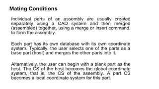
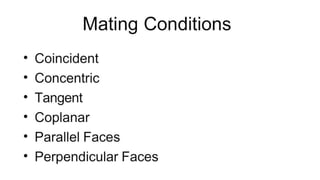
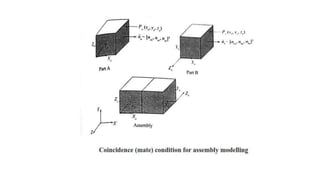
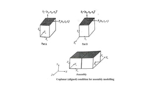
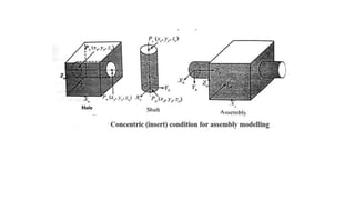
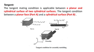
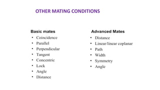
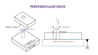
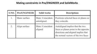
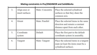
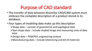
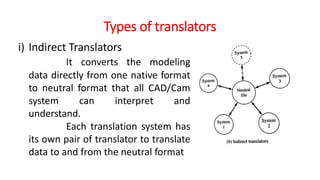
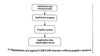
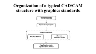
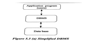
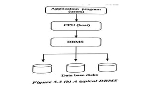
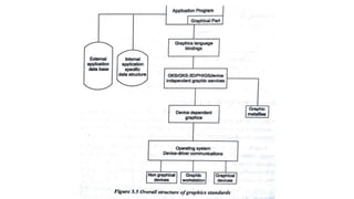
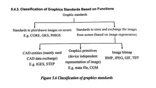
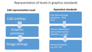
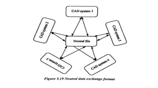
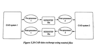
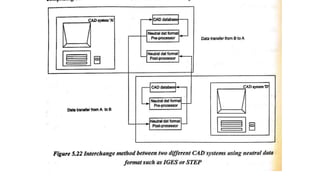
UNIT -III
ASSEMBLY OF PARTS AND
CAD STANDARDS
(c) Combination approach:
• In this approach, the basic geometry for a part is
first established, then it is brought into an assembly
for further refinements.
Hierarchical Relationship
COINCIDENT MATING:
The coincident mating condition is applied between to
planar faces and it forces them to be in touch with each
other.
 This condition is also called “against” condition.
Shown in Figure Coincident condition applied between
planar faces of two solid blocks such as part A and part
B.
Coplanar (Aligned):
 The coplanar mating condition is applied between two
planar faces and it forces them to lie in the same
plane.
 Figure shows the coplanar or aligned mating
condition applied between planar faces of two solid
blocks such as part A and part B.
Concentric (Insert):
 The concentric mating condition also called “fit” condition is applied
between two cylindrical faces such as a cylindrical face of a shaft and
cylindrical face of a hole.
 Shown in Figure The concentric mating condition is achieved by forcing
the axes to become collinear. Each axis is defined by two points.
Tangent:
The tangent mating condition is applicable between a planar and
cylindrical surface of two cylindrical surfaces. The tangent condition
between a planar face (Part A) and a cylindrical surface (Part B) .
OTHER MATING CONDITIONS
PERPENDICULAR FACES
Mating constraints in Pro/ENGINEER and SolidWorks
Purpose of CAD standard
• The transfer of data between dissimilar CAD/CAM system must
embrace the complete description of a product stored in its
database.
• Four types of modeling data make up this description
Shape data – consists of geometrical and topological data
Non-shape data – include shaded image and measuring units of data
base
Design data – FEM/FEA, engineering analysis
Manufacturing data – include tolerencing and bill of materials
Types of translators
i) Direct Translators
 It entails translating the
modeling data directly from one
native format to another.
 Direct translator convert data
directly in one step.
Types of translators
i) Indirect Translators
It converts the modeling
data directly from one native format
to neutral format that all CAD/Cam
system can interpret and
understand.
Each translation system has
its own pair of translator to translate
data to and from the neutral format
Organization of a typical CAD/CAM
structure with graphics standards
DATABASE MANAGEMENT
• Database is a collection of data at a single location to be used by
various people for different applications.
OBJECTIVES OF DATABASE
• It provides security
• It shares the data among users
• It incorporates the changes quickly and effectively
• It improves accuracy and integrity of data
• It reduces the cost of storage and retrieval of data
• It reduces or eliminates the redundant data
STANDARDS FOR COMPUTER
GRAPHICS
• Need for graphic standards
• There is a need for portability of the geometric model among different
hardware platforms.
• Where there is a situation to exchange drawing database among software
packages.
• There is a need for exchanging graphic data between different computer
systems.
• There is a need for the requirement of graphic data exchange formats and their
details such as IGES, DXF and STEP.
CLASSIFICATION OF CAD
STANDARDS
• Graphic and computing standards
• Data exchange standards
• Communication standards
GRAPHIC AND COMPUTING
STANDARDS
• Aim for graphics standardisation
• To allow the transfer of graphic data between two or more different companies
which may have completely different CAD systems.
• To control all types of graphic devices such as plotters and display devices in a
consistent manner.
• To provide the complete range of graphical facilities in 2D including the
interactive capabilities.
• To be small enough for a variety of programs.
Types of Graphics standards
• GKS-GRAPHICS KERNEL SYSTEM
• PHIGS-Programmers Hierarchical Interactive Graphics Standard
• CORE
• GKS-3D
• IGES- Initial Graphics Exchange Specification
GKS (GRAPHICS KERNEL SYSTEM)
• Series of commands used for graphical operations.
• Number of elements that may be drawn in an image is known as
graphical primitives.
Representation of levels in graphics standards
CAD entities
Graphics
primitives
Image bitmap
CAD data exchange
standards – IGES,
STEP
Device independent
picture description –
Metafile, e.g, CGM
Bitmap standards –
e.g, GIF, TIFF
CAD representation Level Equivalent standards
Features of GKS
• It is an independent device. So it can work with all types of input and
output devices.
• All text and annotation can be prepared and stored natural languages.
• Graphic functions are defined for both 2D and 3D.
• It includes all types of display elements.
• GKS supports picture data into two routines.
• GKS defines an international coordinate system called normalized
device coordinates.
STANDARDS FOR EXCHANGE
IMAGES
• The purpose of GKS and other similar standards is to allow graphics
to be drawn on a display device by an application program.
• The model is converted by the series of graphics primitives, and these
are then displayed on the screen using the graphics procedures,
typically by setting the values of the pixels in a rectangular raster
array.
• The raster array is represented by a region of computer memory is
known as bitmap.
PHIGS - Programmers Hierarchical
Interactive Graphics Standard
• PHIGS is an improved version of GKS. It offers the extended set of
primitives for graphical elements from which models may be
generated.
• It is mainly used in high functional systems.
Features of PHIGS
• It has very high interactivity
• It has a real time modification of graphical data
• Data input is in hierarchical structure
• It supports geometric animation
OPEN GRAPHICS LIBRARY
• OpenGL (Open Graphics Library) is a cross-language, multi-
platform application programming interface (application program
interface-API) for rendering2D and 3D vector graphics.
• The API is typically used to interact with a graphics processing
unit (GPU), to achieve hardware-accelerated rendering.
• Silicon Graphics Inc.,(SGI) started developing OpenGL in 1991.
• Open GL does not require high performance display hardware to
be present, but it require a frame buffer memory that stores the
raster display bitmap.
• Open GL draws directly in to the frame buffer but also allows the
use of multiple buffer where for e.g., one buffer is displayed while
second is being updated.
• It is extensively used in the fields of CAD, virtual reality, scientific
visualization, information visualization, flight simulation and
video games.
Features of OpenGL
• Based on IRIS GL (Integrated raster imaging system graphics
library)
• Low level
• Fine grained control
• Modal
• Frame Buffer
• Not programmable
• Geometry and images
Advantages of OpenGL
• Industry standard
• Stable
• Reliable and portable
• Evolving
• Scalable
• Easy to use
Data exchange standards
• CAD data exchange involves a number of software technologies and
methods to translate data from one Computer-aided design system to
another CAD file format.
• The recent decades, the data transfer of data between the system has
been made possible by the neutral format of data exchange.
The following reasons for exchanging the data are that
• All use the same cad package
• Special translator applications are used to change the data from one
format to another format needed.
• A neutral format is used for data exchange.
Requirements of data exchange
• Shape data
• Non shape data
• Design data
• Manufacturing data
Methods for data exchange
• Direct CAD system export/import
• Direct translation software
• Neutral data exchange format
Development of Data Exchange Format
• The significant work in data exchange was started in 1979 of an Initial
Graphics Exchange Specification (IGES) which was supported by US
national Bureau of standards.
• Boeing and GE were chosen due to their prior experience in
developing data exchange formats – Boeing with its CIIN (CAD
Integrated Information Network)
• IGES owned very good support among the CAD users and vendors.
IGES has three types of entity:
• Geometric – it defines the product shape and include curves, surface
and solids
• Annotation – it included various types of dimensions (linear, angular,
ordinate), centre line , notes, general labels, symbols and cross
hatching
• Structure – it includes views, drawing , attributes( such as line and text
fonts, colors and layers), properties (mass), subfigures and external
cross reference entities (for surface and assemblies)
Error handling
• While importing IGES file, error handling is very important
• There are two major error sources when processing IGES files
Program errors in the processors
Misinterpretation of the IGES standard itself.
• The way an IGES processor report error is – the processor should
report the entity type, number of unprocessed entries, reason for un-
processing and other relevant database information of these
unprocessed entities.
• IGES should also report any invalid or missing data encountered in
reading IGES files especially those that were edited.
STEP
• STEP ( standard for Exchange of Product Data) is an exchange for
product data in support of industrial automation
CALS
• Continuous Acquisition and Life cycle support is CALS.
• CALS was originally called Computer Aided Acquisition and Logistics
Support.
COMMUNICATION STANDARDS
• Data exchange depends not only on the compatibility of the
applications data formats between the communicating systems.
• LAN (Local area networks)
• WAN (Wide area networks)
LAN
WAN

Unit 3-ASSEMBLY OF PARTS AND CAD STANDARDS.pptx

  • 1.
    UNIT -III ASSEMBLY OFPARTS AND CAD STANDARDS
  • 6.
    (c) Combination approach: •In this approach, the basic geometry for a part is first established, then it is brought into an assembly for further refinements.
  • 7.
  • 12.
    COINCIDENT MATING: The coincidentmating condition is applied between to planar faces and it forces them to be in touch with each other.  This condition is also called “against” condition. Shown in Figure Coincident condition applied between planar faces of two solid blocks such as part A and part B.
  • 14.
    Coplanar (Aligned):  Thecoplanar mating condition is applied between two planar faces and it forces them to lie in the same plane.  Figure shows the coplanar or aligned mating condition applied between planar faces of two solid blocks such as part A and part B.
  • 16.
    Concentric (Insert):  Theconcentric mating condition also called “fit” condition is applied between two cylindrical faces such as a cylindrical face of a shaft and cylindrical face of a hole.  Shown in Figure The concentric mating condition is achieved by forcing the axes to become collinear. Each axis is defined by two points.
  • 18.
    Tangent: The tangent matingcondition is applicable between a planar and cylindrical surface of two cylindrical surfaces. The tangent condition between a planar face (Part A) and a cylindrical surface (Part B) .
  • 19.
  • 21.
  • 22.
    Mating constraints inPro/ENGINEER and SolidWorks
  • 23.
    Mating constraints inPro/ENGINEER and SolidWorks
  • 25.
    Purpose of CADstandard • The transfer of data between dissimilar CAD/CAM system must embrace the complete description of a product stored in its database. • Four types of modeling data make up this description Shape data – consists of geometrical and topological data Non-shape data – include shaded image and measuring units of data base Design data – FEM/FEA, engineering analysis Manufacturing data – include tolerencing and bill of materials
  • 26.
    Types of translators i)Direct Translators  It entails translating the modeling data directly from one native format to another.  Direct translator convert data directly in one step.
  • 27.
    Types of translators i)Indirect Translators It converts the modeling data directly from one native format to neutral format that all CAD/Cam system can interpret and understand. Each translation system has its own pair of translator to translate data to and from the neutral format
  • 29.
    Organization of atypical CAD/CAM structure with graphics standards
  • 30.
    DATABASE MANAGEMENT • Databaseis a collection of data at a single location to be used by various people for different applications.
  • 31.
    OBJECTIVES OF DATABASE •It provides security • It shares the data among users • It incorporates the changes quickly and effectively • It improves accuracy and integrity of data • It reduces the cost of storage and retrieval of data • It reduces or eliminates the redundant data
  • 34.
    STANDARDS FOR COMPUTER GRAPHICS •Need for graphic standards • There is a need for portability of the geometric model among different hardware platforms. • Where there is a situation to exchange drawing database among software packages. • There is a need for exchanging graphic data between different computer systems. • There is a need for the requirement of graphic data exchange formats and their details such as IGES, DXF and STEP.
  • 35.
    CLASSIFICATION OF CAD STANDARDS •Graphic and computing standards • Data exchange standards • Communication standards
  • 36.
    GRAPHIC AND COMPUTING STANDARDS •Aim for graphics standardisation • To allow the transfer of graphic data between two or more different companies which may have completely different CAD systems. • To control all types of graphic devices such as plotters and display devices in a consistent manner. • To provide the complete range of graphical facilities in 2D including the interactive capabilities. • To be small enough for a variety of programs.
  • 39.
    Types of Graphicsstandards • GKS-GRAPHICS KERNEL SYSTEM • PHIGS-Programmers Hierarchical Interactive Graphics Standard • CORE • GKS-3D • IGES- Initial Graphics Exchange Specification
  • 41.
    GKS (GRAPHICS KERNELSYSTEM) • Series of commands used for graphical operations. • Number of elements that may be drawn in an image is known as graphical primitives.
  • 43.
    Representation of levelsin graphics standards CAD entities Graphics primitives Image bitmap CAD data exchange standards – IGES, STEP Device independent picture description – Metafile, e.g, CGM Bitmap standards – e.g, GIF, TIFF CAD representation Level Equivalent standards
  • 44.
    Features of GKS •It is an independent device. So it can work with all types of input and output devices. • All text and annotation can be prepared and stored natural languages. • Graphic functions are defined for both 2D and 3D. • It includes all types of display elements. • GKS supports picture data into two routines. • GKS defines an international coordinate system called normalized device coordinates.
  • 48.
    STANDARDS FOR EXCHANGE IMAGES •The purpose of GKS and other similar standards is to allow graphics to be drawn on a display device by an application program. • The model is converted by the series of graphics primitives, and these are then displayed on the screen using the graphics procedures, typically by setting the values of the pixels in a rectangular raster array. • The raster array is represented by a region of computer memory is known as bitmap.
  • 51.
    PHIGS - ProgrammersHierarchical Interactive Graphics Standard • PHIGS is an improved version of GKS. It offers the extended set of primitives for graphical elements from which models may be generated. • It is mainly used in high functional systems.
  • 52.
    Features of PHIGS •It has very high interactivity • It has a real time modification of graphical data • Data input is in hierarchical structure • It supports geometric animation
  • 54.
    OPEN GRAPHICS LIBRARY •OpenGL (Open Graphics Library) is a cross-language, multi- platform application programming interface (application program interface-API) for rendering2D and 3D vector graphics. • The API is typically used to interact with a graphics processing unit (GPU), to achieve hardware-accelerated rendering. • Silicon Graphics Inc.,(SGI) started developing OpenGL in 1991.
  • 55.
    • Open GLdoes not require high performance display hardware to be present, but it require a frame buffer memory that stores the raster display bitmap. • Open GL draws directly in to the frame buffer but also allows the use of multiple buffer where for e.g., one buffer is displayed while second is being updated. • It is extensively used in the fields of CAD, virtual reality, scientific visualization, information visualization, flight simulation and video games.
  • 56.
    Features of OpenGL •Based on IRIS GL (Integrated raster imaging system graphics library) • Low level • Fine grained control • Modal • Frame Buffer • Not programmable • Geometry and images
  • 58.
    Advantages of OpenGL •Industry standard • Stable • Reliable and portable • Evolving • Scalable • Easy to use
  • 59.
    Data exchange standards •CAD data exchange involves a number of software technologies and methods to translate data from one Computer-aided design system to another CAD file format. • The recent decades, the data transfer of data between the system has been made possible by the neutral format of data exchange.
  • 61.
    The following reasonsfor exchanging the data are that • All use the same cad package • Special translator applications are used to change the data from one format to another format needed. • A neutral format is used for data exchange.
  • 63.
    Requirements of dataexchange • Shape data • Non shape data • Design data • Manufacturing data
  • 64.
    Methods for dataexchange • Direct CAD system export/import • Direct translation software • Neutral data exchange format
  • 68.
    Development of DataExchange Format • The significant work in data exchange was started in 1979 of an Initial Graphics Exchange Specification (IGES) which was supported by US national Bureau of standards. • Boeing and GE were chosen due to their prior experience in developing data exchange formats – Boeing with its CIIN (CAD Integrated Information Network) • IGES owned very good support among the CAD users and vendors.
  • 70.
    IGES has threetypes of entity: • Geometric – it defines the product shape and include curves, surface and solids • Annotation – it included various types of dimensions (linear, angular, ordinate), centre line , notes, general labels, symbols and cross hatching • Structure – it includes views, drawing , attributes( such as line and text fonts, colors and layers), properties (mass), subfigures and external cross reference entities (for surface and assemblies)
  • 76.
    Error handling • Whileimporting IGES file, error handling is very important • There are two major error sources when processing IGES files Program errors in the processors Misinterpretation of the IGES standard itself. • The way an IGES processor report error is – the processor should report the entity type, number of unprocessed entries, reason for un- processing and other relevant database information of these unprocessed entities. • IGES should also report any invalid or missing data encountered in reading IGES files especially those that were edited.
  • 77.
    STEP • STEP (standard for Exchange of Product Data) is an exchange for product data in support of industrial automation
  • 80.
    CALS • Continuous Acquisitionand Life cycle support is CALS. • CALS was originally called Computer Aided Acquisition and Logistics Support.
  • 81.
    COMMUNICATION STANDARDS • Dataexchange depends not only on the compatibility of the applications data formats between the communicating systems. • LAN (Local area networks) • WAN (Wide area networks)
  • 82.
  • 83.