Downloaded 718 times
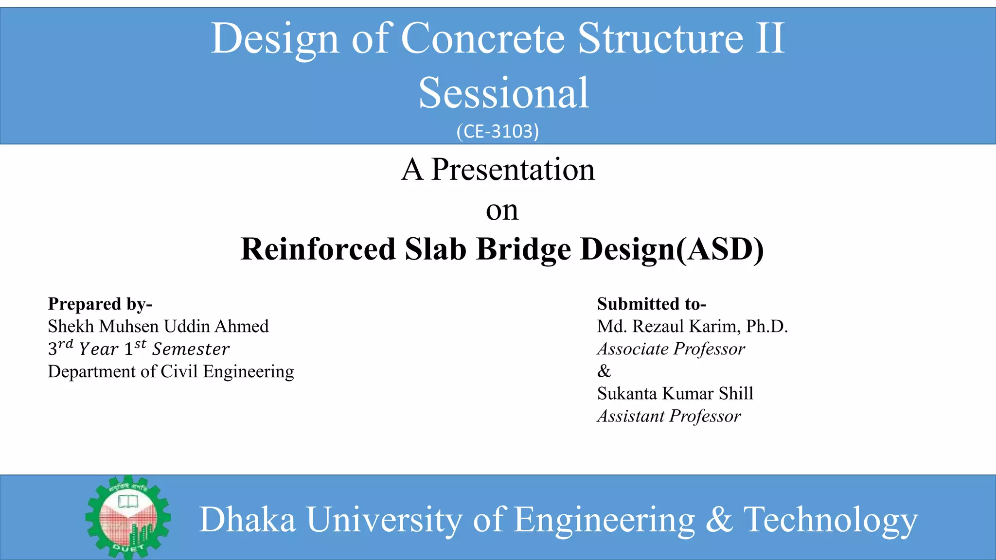


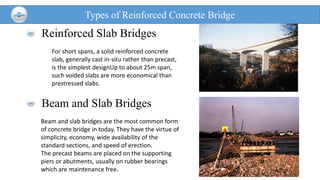
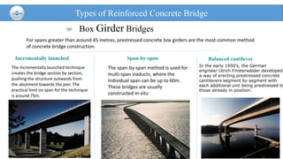
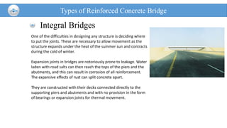
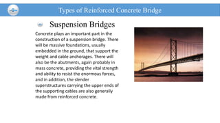
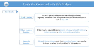
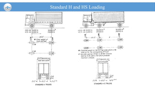
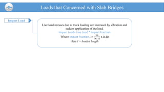
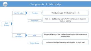
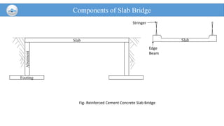
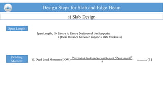
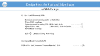
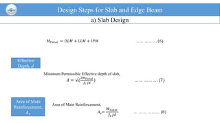
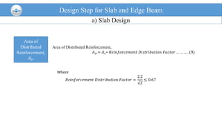
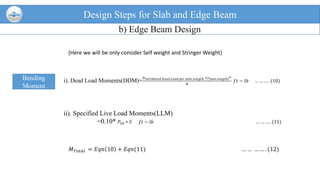
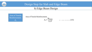
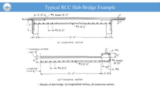


This document provides an overview of reinforced concrete slab bridge design. It discusses the types of reinforced concrete bridges, including slab, beam and slab, arch, box girder, cable-stayed, and integral bridges. It also outlines the loads that must be considered in slab bridge design, including truck, other roadway, sidewalk, and impact loads. Finally, it details the design steps for slab and edge beam components, including calculating bending moments from dead and live loads, determining the effective depth, area of main and distributed reinforcement, and designing the edge beam reinforcement.


