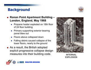
Download as PDF, PPTX


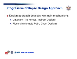
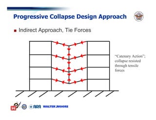


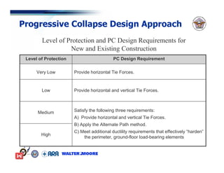


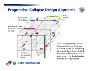
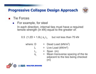


The document summarizes the Department of Defense's Unified Facilities Criteria (UFC) 4-023-03 for designing buildings to resist progressive collapse. The UFC provides guidelines for assessing the risk of progressive collapse and designing structures to reduce this risk. It requires consideration of tie forces and alternate load paths. Most DOD structures will require low levels of protection through tie forces only. The UFC aims to reduce progressive collapse risk in a practical manner based on the structure's importance. Feedback will be used to refine the guidelines over time.


![Geotechnical Engineering-II [Lec #25: Coulomb EP Theory - Numericals]](https://cdn.slidesharecdn.com/ss_thumbnails/25-181123050611-thumbnail.jpg?width=640&height=640&fit=bounds)