This study compares the design and cost efficiency of various bridge superstructures: RCC solid slab, RCC I girder, and voided slab, focusing on a 20 m span. It concludes that voided slabs are more economical and reduce dead weight without compromising structural integrity, making them preferable over solid slabs and girders for the specified dimensions. The analysis, conducted using STAAD Pro, evaluates bending moments, shear forces, and construction costs under specified loading conditions according to IRC standards.
![International Journal of Trend in Scientific Research and Development @ www.ijtsrd.com eISSN: 2456-6470
@ IJTSRD | Unique Paper ID – IJTSRD47679 | Volume – 5 | Issue – 6 | Sep-Oct 2021 Page 1580
for voided slab for same span of the bridge having
same width of the structure.
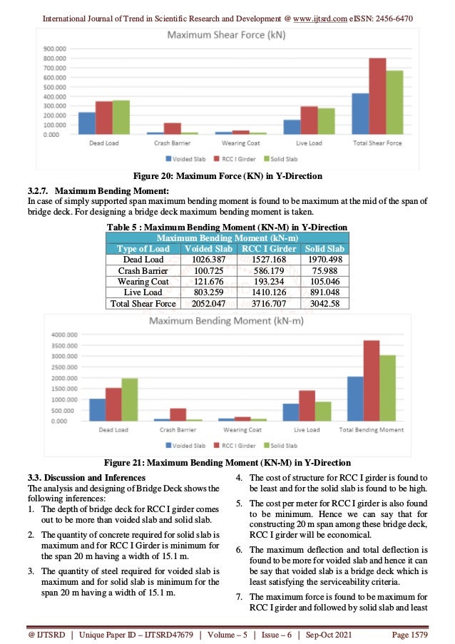
8. The maximum bending moment is also found to
be most for RCC I girder and followed by Solid
slab and least for voided slab for same span of the
bridge having same width of the structure.
4. Conclusion
1. Considering all the above inference made on
analysis and designing of all bridge deck, we
finally conclude that the RCC I girder is most
economical bridge deck for 20 m span having a
width of 15.1 m width of structure.
2. In RCC I Girder it is also seen in from the study
that maximum displacement comes out to be
lowest and maximum shear force and maximum
bending moment comes out to be highest.
3. The quantity of concrete is found to be lowest
among rest of other bridge deck and quantity of
steel is found to be second lowest among rest of
other bridge deck but at last overall economy of
bridge is seen, it found that total cost and cost per
running meter is lowest for RCC I Girder.
References
[1] Singh Shailendra*, Jain Utkarsh, Nimoriya
Manish Kumar, Faraz Md. Islamuddin, Volume
3, Issue 3, May-June, 2015 a comparative study
of simply supported and continuous r. c. c. slab
bridges, International Journal of Engineering
Research and General Science (IJERGS), pp.
1510-1520.
[2] Sonal R. Naik, Volume 04 Issue 01, July-2017
A Voided Slab and Conventional Flat Slab; A
Comparative Study, International Journal of
Science Technology & Engineering (IJSTE),
pp. 44-50.
[3] Kalpana Mohan, Volume 07 Issue 05,
September-October 2016, analysis of bridge
girder with beam and without beam,
International Journal of Civil Engineering and
Technology (IJCIET). pp. 337–346.
[4] K. Hemalathaa, ChippymolJamesb, L.
Natrayanc, V. Swamynadhd, Volume 5
July2020 Analysis of RCC T beam and
prestressed concrete box girder bridge
superstructure under different span conditions,
https://www.researchgate.net/publication/34874
0833, and pp. 1-11.
[5] Rahul Gangwar, Ankur Pratap Singh, T. N.
Pandey, Volume 7 Issue 4, April 2020
Comparative Study of RCC and PSC Girder,
International Research Journal of Engineering
and Technology (IRJET), pp. 3884 -3888.
[6] Rajesh F. Kale, N. G. Gore, P. J. Salunke,
Volume-3, Issue-6 January 2014, Cost
Optimization of R. C. C. T-Beam Girder,
International Journal of Soft Computing and
Engineering (IJSCE), pp. 184-187.
[7] Anamika Tedia, Volume 11, Issue 1 Ver. II
(Jan. 2014), Cost, Analysis and Design of
Steel-Concrete Composite Structure Rcc
Structure, OSR Journal of Mechanical and Civil
Engineering (IOSR-JMCE), pp. 54-59.
[8] C. S Surana, “Grillage analogy”, Narosa
Publishing House, New Delhi, India.
[9] Neal Bettigole Rita Robison a book of Bridge
Decks.
[10] E. C Hambly a ” Book of Bridge Deck
Behavior”.
[11] N. Krishna Raju a book of Design of Bridges.
[12] T. R. Jagadeesh & M. A. Jayaram - Design of
Bridge structure.
[13] Standard Specification & Code of Practices for
Road Bridges” Seventh Revision IRC: 6:2017.
[14] Code of Practices for Concrete Road Bridges”
First Revision IRC: 112:2020.
[15] First Revision IRC: SP: 64-2016 “Guideline for
the analysis and design of cast in place voided
slab Superstructure”.](https://image.slidesharecdn.com/233comparativeanalysisanddesignofvoidedslabandrccigirderwithsolidslabinbridgestructure-220307050932/95/Comparative-Analysis-and-Design-of-Voided-Slab-and-RCC-I-Girder-with-Solid-Slab-in-Bridge-Structure-14-638.jpg)


