Downloaded 328 times


![BRIDGE DESIGN 31
(B) Modified Ingis Formula : (Upper parts of Western Ghats)
Where Q = Discharge in cusecs (ft
3
/s)
A = Catchment area in sq.miles.
(C) Dicken’s Formula (for Vidarbha & Marathwada Regions)
Where Q = Discharge in cusecs (ft
3
/s)
A = Catchment area in sq. miles.
C = Constant whose value varies from 800 to 1600
= 800 to 1000 for rainfall 25" to 50"
= 1000 to 1400 generally this value taken in M.P can be
adopted for Vidarbha adjacent to Madhya Pradesh
= 1400 to 1600 in Western Ghats.
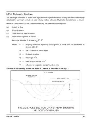
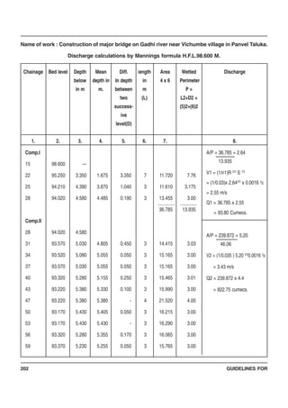
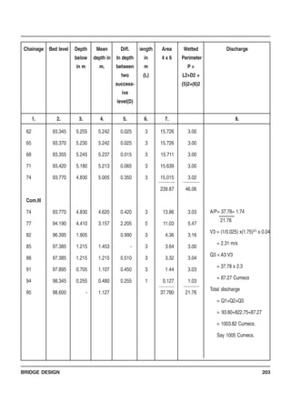
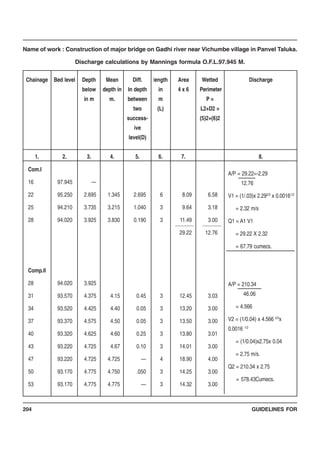
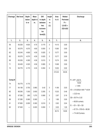
The discharge is then calculated at the assumed H.F.L. by using Manning’s formula. The discharge
calculated by Manning’s formula is tallied with the discharge obtained from above empirical formulae. By
trial and error the H.F.L. is fixed.
The discharge calculated by the Manning’s formulae is tallied with the discharge by above empirical
formulae for the Catchments Area up to the bridge site. In the areas where ‘Inglis flood’ is not expected, the
discharge calculated by Manning’s formulae is tallied with either Modified Inglis formula or Dicken’s
formula. If the discharge calculated by Manning’s formulae is less than the above empirical formulae
discharge, the H.F.L. is raised suitably to get the ‘designed H.F.L.’ and vice-versa. The bridge is designed
on the basis of H.F.L. so fixed with due consideration to observed flood level.
2.2.1.2 Discharge by Unit hydrograph Method
The Unit Hydrograph, frequently termed as the unit graph, is defined as the hydrograph of storm run-off at
a given point in a river, resulting from an isolated rainfall of unit duration occurring uniformly over the
catchment, and producing a unit run-off. The unit run-off adopted is 1 cm depth over a catchment area.
The term “Unit-Rainfall Duration” is the duration of rainfall excess resulting in the unit hydrograph. Usually,
unit hydrographs are derived for specified unit durations, say, 6 hours, 12 hours. etc., and derived unit
hydrographs for durations other than these are converted into unit hydrographs of the above unit durations.
The duration selected should not exceed the period during which the storm is assumed to be approximately
4A
A4000
Q
+
=
[ ] 4
3
ACQ =](https://image.slidesharecdn.com/guidelinesbridgedesign-161107181659/85/Guide-lines-bridge_design-31-320.jpg)


This document provides guidelines for bridge design in the Public Works Department. It introduces the contents and chapters, which cover aspects of bridge design, components, innovative structures, preparation of bridge projects, and other topics. The guidelines are intended to help engineers understand the department's practices for bridge design. The second edition was revised with new chapters and information to aid both new and experienced engineers.


![Resumen vasos faciales[1]](https://cdn.slidesharecdn.com/ss_thumbnails/resumenvasosfaciales1-140505194346-phpapp01-thumbnail.jpg?width=640&height=640&fit=bounds)


