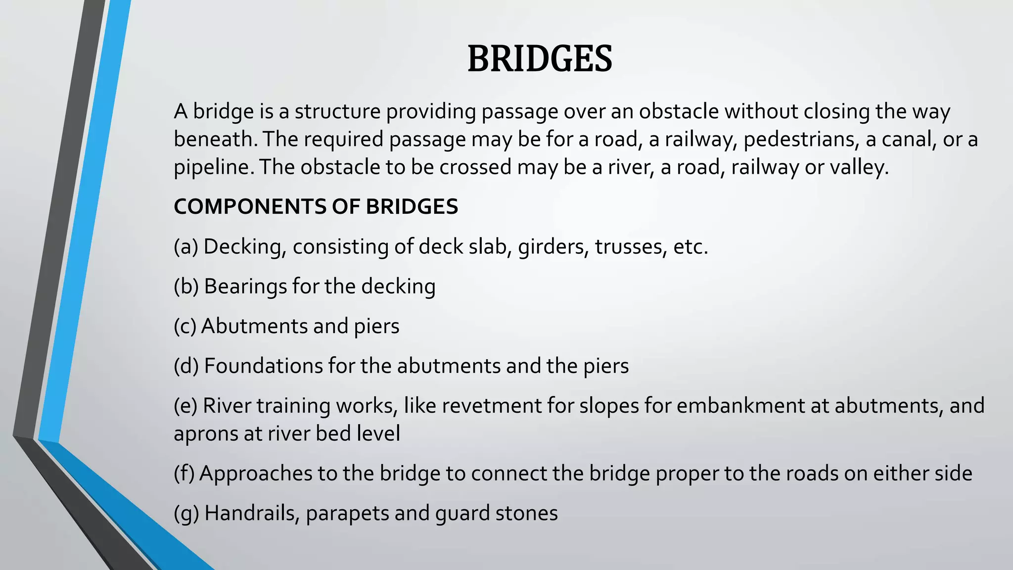
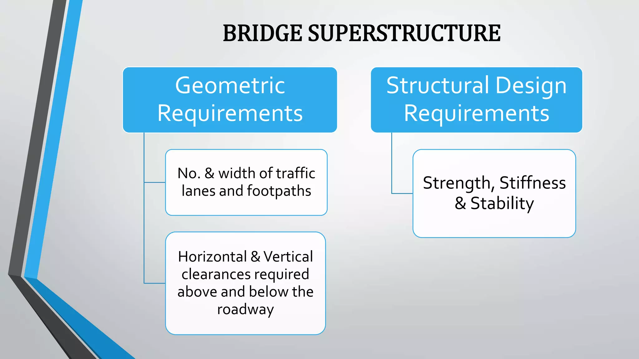
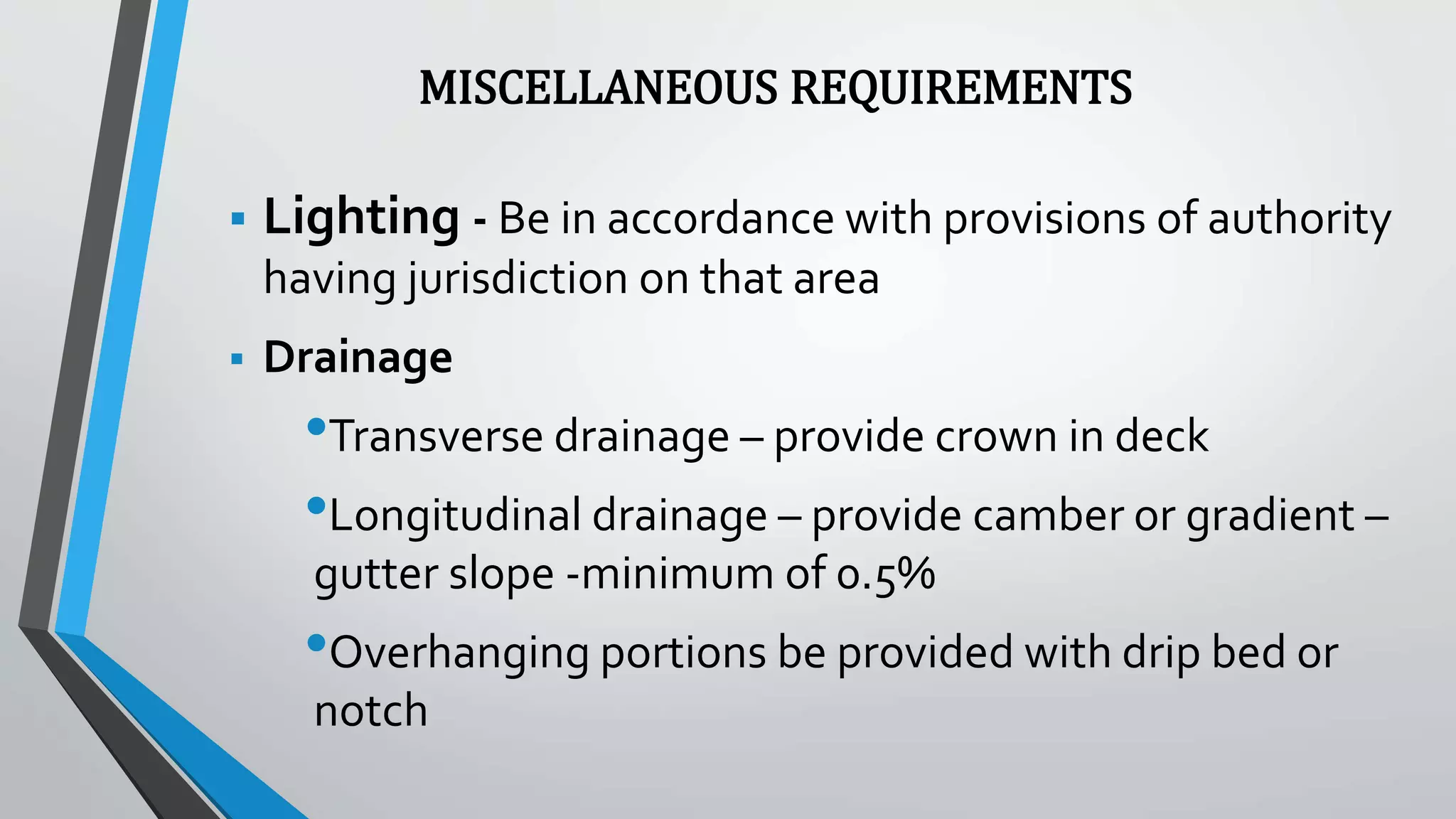
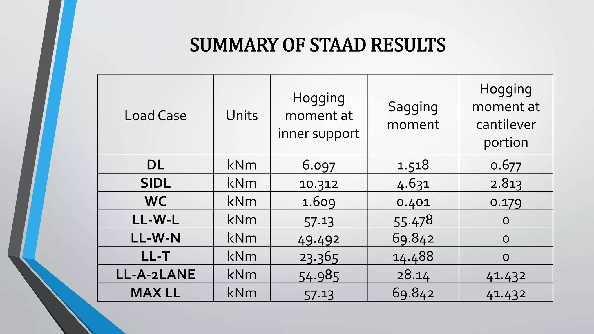
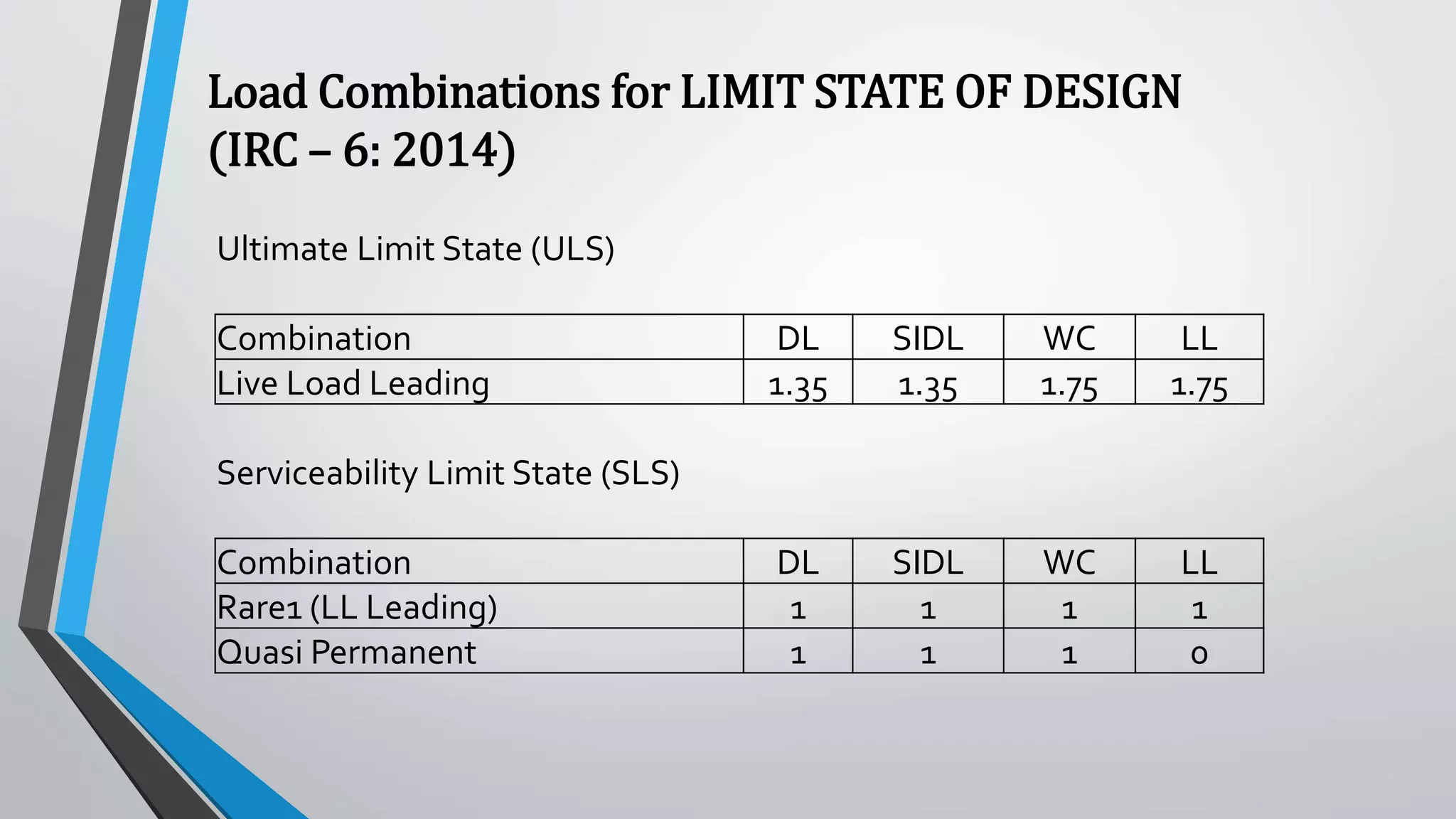
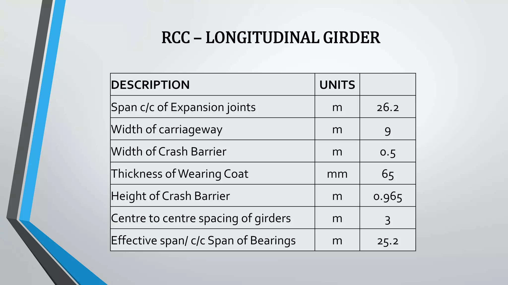
Internship Report on
Bridge Super-structure
Analysis and Design
in LT-IDPL
Elamathy M
Final year
M.E Structural Engineering
Anna University, Chennai
BRIDGES
A bridge is a structure providing passage over an obstacle without closing the way
beneath.The required passage may be for a road, a railway, pedestrians, a canal, or a
pipeline.The obstacle to be crossed may be a river, a road, railway or valley.
COMPONENTS OF BRIDGES
(a) Decking, consisting of deck slab, girders, trusses, etc.
(b) Bearings for the decking
(c) Abutments and piers
(d) Foundations for the abutments and the piers
(e) River training works, like revetment for slopes for embankment at abutments, and
aprons at river bed level
(f) Approaches to the bridge to connect the bridge proper to the roads on either side
(g) Handrails, parapets and guard stones
BRIDGE SUPERSTRUCTURE
Geometric
Requirements
No. & width of traffic
lanes and footpaths
Horizontal &Vertical
clearances required
above and below the
roadway
Structural Design
Requirements
Strength, Stiffness
& Stability
MISCELLANEOUS REQUIREMENTS
 Lighting - Be in accordance with provisions of authority
having jurisdiction on that area
 Drainage
•Transverse drainage – provide crown in deck
•Longitudinal drainage – provide camber or gradient –
gutter slope -minimum of 0.5%
•Overhanging portions be provided with drip bed or
notch
MISCELLANEOUS REQUIREMENTS
 Road- Kerb - Surmountable & Insurmountable
 Parapet – Designed to prevent a fast moving vehicle of a
given mass from shooting off the roadway- Minimum
700 mm height – New Jersey Barrier – road side face
double sloped
 Hand Rail – parapets be mounted by metal hand rail –
minimum 350 mm height
(Above features be given deliberate vertical cuts or discontinuity to prevent monolithic action
with deck slab )
MISCELLANEOUS REQUIREMENTS
 Crash Barriers – Protect walkways from erring vehicular
traffic by acting as an insurmountable kerb and deflect
the hitting vehicles back into the traffic lane – corrugated
or pressed metal sheet spanning horizontally between
posts.
 Super-elevation – Be in accordance with the applicable
standard for the highway ( less than 0.08 m/m -
preferably less than 0.06 m/m )
MISCELLANEOUS REQUIREMENTS
Expansion joints – Joints should be sealed to prevent
erosion and filling of debris.
Types of expansion joints:
• Field moulded joints – Excessive maintenance problems
• Compression seals – Good service life
• Compression-tension seals – Require careful consideration of thermal thrust
• Steel plates and finger joints – Costly & difficult to maintain
LOADS ACTING ON BRIDGE SUPERSTRUCTURE
• Dead Load
• Super Imposed Dead Load
• Live Load
• Snow Load
• Impact factor on vehicular live load
• Wind load
• Longitudinal forces
• Centrifugal force
• Buoyancy
• Temperature effects
• Seismic force
• Erection Effects
LOAD COMBINATIONS
ULTIMATE LIMIT STATE:
The structural strength under limit state shall be estimated in order to avoid
internal failure or excessive deformation.The equilibrium and the structural
strength shall be checked under basic, accidental and seismic combinations of
loads.
SERVICEABILITY LIMIT STATE:
The serviceability limit state check shall be carried out in order to have control
on stress, deflection, crack width, settlement and to estimate shrinkage and
creep effects.
ANALYSIS & DESIGN OF SUPERSTRUCTURE
•Elastic behaviour of structure
ANALYSIS
•Elastic (working ) Strength basis
•Load-factored (Ultimate) Strength basis
•Serviceability criteria
DESIGN
RCC T-BEAM BRIDGES
• T-Beam construction consists of a transversely reinforced slab
deck which spans across to the longitudinal support girders.
• T-Beam bridges are economical for spans 12m to 18m.
• Optimum lateral spacing of longitudinal girders is typically
between 1.8 m to 3m.
DESCRIPTION UNITS
Span length from EJ to EJ m 26.2
Centre of bearing to centre of EJ m 0.5
Length of effective span m 25.2
Width of Carriageway m 8
Depth of Slab mm 230
Width of slab mm 1000
Clear cover mm 40
Width of Crash Barrier m 0.5
Area of Crash Barrier mm2
0.3
C/C Spacing of Girders m 3
Depth of Girder m 2.1
Thickness of Wearing Coat mm 65
DECK SLAB
ANALYSIS OF DECK SLAB
Concrete bridge decks are designed as transverse strips as a flexure
member. Carriage way width is modelled as line in Staad Pro.The
concrete deck is assumed to be transverse slab strips of 1 m width,
which is supported by the girders.
DL, SIDL & LL ( Class A, Class 70 R-W, Class 70 R-T) cases are
considered for the analysis.
BENDING MOMENT ENVELOPE FOR LIVE LOAD CLASS-A
2 LANE
SUMMARY OF STAAD RESULTS
Load Case Units
Hogging
moment at
inner support
Sagging
moment
Hogging
moment at
cantilever
portion
DL kNm 6.097 1.518 0.677
SIDL kNm 10.312 4.631 2.813
WC kNm 1.609 0.401 0.179
LL-W-L kNm 57.13 55.478 0
LL-W-N kNm 49.492 69.842 0
LL-T kNm 23.365 14.488 0
LL-A-2LANE kNm 54.985 28.14 41.432
MAX LL kNm 57.13 69.842 41.432
Ultimate Limit State (ULS)
Combination DL SIDL WC LL
Live Load Leading 1.35 1.35 1.75 1.75
Serviceability Limit State (SLS)
Combination DL SIDL WC LL
Rare1 (LL Leading) 1 1 1 1
Quasi Permanent 1 1 1 0
Load Combinations for LIMIT STATE OF DESIGN
(IRC – 6: 2014)
RCC – LONGITUDINAL GIRDER
DESCRIPTION UNITS
Span c/c of Expansion joints m 26.2
Width of carriageway m 9
Width of Crash Barrier m 0.5
Thickness ofWearing Coat mm 65
Height of Crash Barrier m 0.965
Centre to centre spacing of girders m 3
Effective span/ c/c Span of Bearings m 25.2
GRILLAGE ANALYSIS OF GIRDER
• Deck is idealized as a series of ‘beam’ elements (or grillages),
connected and restrained at their joints.
• Each element is given an equivalent bending and torsional inertia
to represent the portion of the deck which it replaces.
• Bending and torsional stiffness in every region of slab are
assumed to be concentrated in nearest equivalent grillage beam.
• Restraints, load and supports may be applied at the joints
between the members, and members framing into a joint may be
at any angle.
SUMMARY OF STAAD RESULTS FOR INTERMEDIATE GIRDER AT
DIFFERENT SECTIONS
GIRDER-2
LOAD CASES
Maximum Shear Force Maximum Bending Moment
L=d L/4 L/2 3L/4 L=L-d L=d L/4 L/2 3L/4 L=L-d
Distance from Centre of Bearing
(mm)
2258 6300 12600 18900 22942 2258 6300 12600 18900 22942
Beam No. 81 149 548 446 378 81 149 548 446 378
At distance 0.958 1 1 1 1 0.958 1 1 1 1
DL 431.73 291.086 21.042 231.621 390.462 -1079.21 -2359.37 -3421 -2751 -1507
SIDL 25.465 25.361 25.161 25.327 25.444 -57.611 -147.622 -319.3 -185.6 -84.13
WC 41.227 26.047 -0.955 19.617 36.763 -103.507 -222.661 -300.7 -256.9 -144.1
1 lane of 70R wheeled 366.09 144.288 9.474 130.873 281.951 -681.525 -1587.11 -1558 -1665 -966.2
1 lane of 70RTracked 334.99 170.461 -46.6 72.186 250.464 -764.896 -1511.19 -1352 -1602 -1036
2 lane of Class A 212.77 119.712 31.947 104.736 248.062 -496.98 -1104.01 -1412 -1438 850.73
Max LL 366.09 170.461 31.947 130.873 281.951 -764.896 -1587.11 -1558 -1665 -1036
Total 864.5 512.955 77.195 407.438 734.62 -2005.2 -4316.8 -5599 -4858 -2771
STRUCTURAL DESIGN
• Step-1: Assume the width & depth of section; diameter of
reinforcement bars and grades of materials
• Step-2: Determine the design strength of the materials from
IRC-112-2011
• Step-3: Determine the moment of resistance of the assumed
section and check if it is less than the Maximum moment due to
ULS combination of applied loads
• Step-4: Check the adequacy of reinforcement required for the
Under-Reinforced section
STRESS & STRAIN DISTRIBUTION FOR BENDING MOMENT
CALCULATION - IRC-112-2011
• Step-5: Check for shear reinforcement be made according to
IRC-112-2011 provisions (Sections loaded with LL, calculated
based on effective width formula, do not require shear check )
• Step-6: Check for serviceability limit state- Stress calculations be
made for Rare and Quasi-Permanent combinations for short and
long term effects – Checked if stresses are within limits specified
in IRC-112-2011
• Step-7: Check for crack width (less than 0.3 mm) & deflections
(Max. LL Deflection < span/800) are done
MODEL RC DETAIL OF I-GIRDER
BOX CULVERT
Design Data
Dimensions
Clear span (m) 5
Clear height (m) 3
Top slab thickness (m) 0.6
Bottom slab thickness (m) 0.7
Side wall thickness (m) 0.5
Height of fill (for Live load dispersion) (m) 3
Height of fill (for SIDL , Earth pressure calculation) (m) 4
width of crash barrier (m) 0.5
Top & bottom haunch (mm) 150 x 150
Width of carriage way (m) 8.5
Total width (m) 6
Total height (m) 4.3
C/C width (m) 5.5
C/C height (m) 3.65
IDEALISATION OF SUPPORTS
According to "FoundationAnalysis and Design" by Joseph E Bowles
Modulus of subgrade reaction (Ks) 40 x SF x qa
where,
SF - Factor of safety 2.5
qa - Allowable bearing capacity (SBC) (kN/m2) 150
The modulus of subgrade (kN /m3) 15000
Bottom slab divided into 18 parts
length of one divided portion of bottom slab (m) 0.31
Stiffness at outer support (Type-1) (kN/m) 2291.67
Stiffness at interior supports (Type 2) (kN/m) 4583.33
LOADS CONSIDERED FOR ANALYSIS OF BOX CULVERT
• Dead Load
• SIDL- crash barrier
• SIDL- Earth fill + Pavement layer
• Live Load-1
• Live Load-2
• Breaking Force
• Earth Pressure
• Live Load Surcharge
• Live Load Surcharge- 1 Side - LL
Leading
• Active Earth Pressure
• Passive Earth Pressure
• Live Load Surcharge- 1 Side - EP
Leading
LOADING ON LINE MODEL OF BOX CULVERT
BMD & SFD OF BOX CULVERT
SECTIONS WHERE MOMENTS AND SHEAR FORCES ARE
OBTAINED
MODEL RC DETAIL OF BOX CULVERT
CONCLUSION
• Scientific, Social andTechnological dimensions of road
and bridge construction projects were introduced
• T-Beam bridge super-structure was analysed using Staad
Pro and designed by Limit State Method in accordance
to relevant IRC codes
REFERENCES
• IRC 6-2014, Standard Specifications and Code of Practice for Road Bridges, Section II –
Loads and Stresses (5th Revision) , Indian Road Congress
• IRC 112-2011, Code of Practice for Concrete Road Bridges, Indian Road Congress
• IRC-5-2015, Standard Specifications and Code of Practice for Road Bridges, Section I-
General Features of Design (8th Revision), Indian Road Congress
• V.K. Raina,Concrete Bridge Practice,Analysis, Design and Economics, 2nd edition,TATA
McGraw-Hill PublishingCompany Ltd, 1994
• Joseph E Bowles, Foundation Analysis and Design, 5th edition, McGraw-Hill, 1996
• JohnsonVictor D, Essentials of Bridge Engineering, 6th edition, Oxford & IBH Publishing
Company Pvt. Ltd, 2008.
THANKYOU

Analysis & design of T-Beam bridge

  • 1.
    Internship Report on BridgeSuper-structure Analysis and Design in LT-IDPL Elamathy M Final year M.E Structural Engineering Anna University, Chennai
  • 2.
    BRIDGES A bridge isa structure providing passage over an obstacle without closing the way beneath.The required passage may be for a road, a railway, pedestrians, a canal, or a pipeline.The obstacle to be crossed may be a river, a road, railway or valley. COMPONENTS OF BRIDGES (a) Decking, consisting of deck slab, girders, trusses, etc. (b) Bearings for the decking (c) Abutments and piers (d) Foundations for the abutments and the piers (e) River training works, like revetment for slopes for embankment at abutments, and aprons at river bed level (f) Approaches to the bridge to connect the bridge proper to the roads on either side (g) Handrails, parapets and guard stones
  • 3.
    BRIDGE SUPERSTRUCTURE Geometric Requirements No. &width of traffic lanes and footpaths Horizontal &Vertical clearances required above and below the roadway Structural Design Requirements Strength, Stiffness & Stability
  • 4.
    MISCELLANEOUS REQUIREMENTS  Lighting- Be in accordance with provisions of authority having jurisdiction on that area  Drainage •Transverse drainage – provide crown in deck •Longitudinal drainage – provide camber or gradient – gutter slope -minimum of 0.5% •Overhanging portions be provided with drip bed or notch
  • 5.
    MISCELLANEOUS REQUIREMENTS  Road-Kerb - Surmountable & Insurmountable  Parapet – Designed to prevent a fast moving vehicle of a given mass from shooting off the roadway- Minimum 700 mm height – New Jersey Barrier – road side face double sloped  Hand Rail – parapets be mounted by metal hand rail – minimum 350 mm height (Above features be given deliberate vertical cuts or discontinuity to prevent monolithic action with deck slab )
  • 6.
    MISCELLANEOUS REQUIREMENTS  CrashBarriers – Protect walkways from erring vehicular traffic by acting as an insurmountable kerb and deflect the hitting vehicles back into the traffic lane – corrugated or pressed metal sheet spanning horizontally between posts.  Super-elevation – Be in accordance with the applicable standard for the highway ( less than 0.08 m/m - preferably less than 0.06 m/m )
  • 8.
    MISCELLANEOUS REQUIREMENTS Expansion joints– Joints should be sealed to prevent erosion and filling of debris. Types of expansion joints: • Field moulded joints – Excessive maintenance problems • Compression seals – Good service life • Compression-tension seals – Require careful consideration of thermal thrust • Steel plates and finger joints – Costly & difficult to maintain
  • 10.
    LOADS ACTING ONBRIDGE SUPERSTRUCTURE • Dead Load • Super Imposed Dead Load • Live Load • Snow Load • Impact factor on vehicular live load • Wind load • Longitudinal forces • Centrifugal force • Buoyancy • Temperature effects • Seismic force • Erection Effects
  • 11.
    LOAD COMBINATIONS ULTIMATE LIMITSTATE: The structural strength under limit state shall be estimated in order to avoid internal failure or excessive deformation.The equilibrium and the structural strength shall be checked under basic, accidental and seismic combinations of loads. SERVICEABILITY LIMIT STATE: The serviceability limit state check shall be carried out in order to have control on stress, deflection, crack width, settlement and to estimate shrinkage and creep effects.
  • 12.
    ANALYSIS & DESIGNOF SUPERSTRUCTURE •Elastic behaviour of structure ANALYSIS •Elastic (working ) Strength basis •Load-factored (Ultimate) Strength basis •Serviceability criteria DESIGN
  • 13.
    RCC T-BEAM BRIDGES •T-Beam construction consists of a transversely reinforced slab deck which spans across to the longitudinal support girders. • T-Beam bridges are economical for spans 12m to 18m. • Optimum lateral spacing of longitudinal girders is typically between 1.8 m to 3m.
  • 14.
    DESCRIPTION UNITS Span lengthfrom EJ to EJ m 26.2 Centre of bearing to centre of EJ m 0.5 Length of effective span m 25.2 Width of Carriageway m 8 Depth of Slab mm 230 Width of slab mm 1000 Clear cover mm 40 Width of Crash Barrier m 0.5 Area of Crash Barrier mm2 0.3 C/C Spacing of Girders m 3 Depth of Girder m 2.1 Thickness of Wearing Coat mm 65 DECK SLAB
  • 15.
    ANALYSIS OF DECKSLAB Concrete bridge decks are designed as transverse strips as a flexure member. Carriage way width is modelled as line in Staad Pro.The concrete deck is assumed to be transverse slab strips of 1 m width, which is supported by the girders. DL, SIDL & LL ( Class A, Class 70 R-W, Class 70 R-T) cases are considered for the analysis.
  • 16.
    BENDING MOMENT ENVELOPEFOR LIVE LOAD CLASS-A 2 LANE
  • 17.
    SUMMARY OF STAADRESULTS Load Case Units Hogging moment at inner support Sagging moment Hogging moment at cantilever portion DL kNm 6.097 1.518 0.677 SIDL kNm 10.312 4.631 2.813 WC kNm 1.609 0.401 0.179 LL-W-L kNm 57.13 55.478 0 LL-W-N kNm 49.492 69.842 0 LL-T kNm 23.365 14.488 0 LL-A-2LANE kNm 54.985 28.14 41.432 MAX LL kNm 57.13 69.842 41.432
  • 18.
    Ultimate Limit State(ULS) Combination DL SIDL WC LL Live Load Leading 1.35 1.35 1.75 1.75 Serviceability Limit State (SLS) Combination DL SIDL WC LL Rare1 (LL Leading) 1 1 1 1 Quasi Permanent 1 1 1 0 Load Combinations for LIMIT STATE OF DESIGN (IRC – 6: 2014)
  • 19.
    RCC – LONGITUDINALGIRDER DESCRIPTION UNITS Span c/c of Expansion joints m 26.2 Width of carriageway m 9 Width of Crash Barrier m 0.5 Thickness ofWearing Coat mm 65 Height of Crash Barrier m 0.965 Centre to centre spacing of girders m 3 Effective span/ c/c Span of Bearings m 25.2
  • 20.
    GRILLAGE ANALYSIS OFGIRDER • Deck is idealized as a series of ‘beam’ elements (or grillages), connected and restrained at their joints. • Each element is given an equivalent bending and torsional inertia to represent the portion of the deck which it replaces. • Bending and torsional stiffness in every region of slab are assumed to be concentrated in nearest equivalent grillage beam. • Restraints, load and supports may be applied at the joints between the members, and members framing into a joint may be at any angle.
  • 22.
    SUMMARY OF STAADRESULTS FOR INTERMEDIATE GIRDER AT DIFFERENT SECTIONS GIRDER-2 LOAD CASES Maximum Shear Force Maximum Bending Moment L=d L/4 L/2 3L/4 L=L-d L=d L/4 L/2 3L/4 L=L-d Distance from Centre of Bearing (mm) 2258 6300 12600 18900 22942 2258 6300 12600 18900 22942 Beam No. 81 149 548 446 378 81 149 548 446 378 At distance 0.958 1 1 1 1 0.958 1 1 1 1 DL 431.73 291.086 21.042 231.621 390.462 -1079.21 -2359.37 -3421 -2751 -1507 SIDL 25.465 25.361 25.161 25.327 25.444 -57.611 -147.622 -319.3 -185.6 -84.13 WC 41.227 26.047 -0.955 19.617 36.763 -103.507 -222.661 -300.7 -256.9 -144.1 1 lane of 70R wheeled 366.09 144.288 9.474 130.873 281.951 -681.525 -1587.11 -1558 -1665 -966.2 1 lane of 70RTracked 334.99 170.461 -46.6 72.186 250.464 -764.896 -1511.19 -1352 -1602 -1036 2 lane of Class A 212.77 119.712 31.947 104.736 248.062 -496.98 -1104.01 -1412 -1438 850.73 Max LL 366.09 170.461 31.947 130.873 281.951 -764.896 -1587.11 -1558 -1665 -1036 Total 864.5 512.955 77.195 407.438 734.62 -2005.2 -4316.8 -5599 -4858 -2771
  • 23.
    STRUCTURAL DESIGN • Step-1:Assume the width & depth of section; diameter of reinforcement bars and grades of materials • Step-2: Determine the design strength of the materials from IRC-112-2011 • Step-3: Determine the moment of resistance of the assumed section and check if it is less than the Maximum moment due to ULS combination of applied loads • Step-4: Check the adequacy of reinforcement required for the Under-Reinforced section
  • 24.
    STRESS & STRAINDISTRIBUTION FOR BENDING MOMENT CALCULATION - IRC-112-2011
  • 25.
    • Step-5: Checkfor shear reinforcement be made according to IRC-112-2011 provisions (Sections loaded with LL, calculated based on effective width formula, do not require shear check ) • Step-6: Check for serviceability limit state- Stress calculations be made for Rare and Quasi-Permanent combinations for short and long term effects – Checked if stresses are within limits specified in IRC-112-2011 • Step-7: Check for crack width (less than 0.3 mm) & deflections (Max. LL Deflection < span/800) are done
  • 26.
    MODEL RC DETAILOF I-GIRDER
  • 27.
    BOX CULVERT Design Data Dimensions Clearspan (m) 5 Clear height (m) 3 Top slab thickness (m) 0.6 Bottom slab thickness (m) 0.7 Side wall thickness (m) 0.5 Height of fill (for Live load dispersion) (m) 3 Height of fill (for SIDL , Earth pressure calculation) (m) 4 width of crash barrier (m) 0.5 Top & bottom haunch (mm) 150 x 150 Width of carriage way (m) 8.5 Total width (m) 6 Total height (m) 4.3 C/C width (m) 5.5 C/C height (m) 3.65
  • 28.
    IDEALISATION OF SUPPORTS Accordingto "FoundationAnalysis and Design" by Joseph E Bowles Modulus of subgrade reaction (Ks) 40 x SF x qa where, SF - Factor of safety 2.5 qa - Allowable bearing capacity (SBC) (kN/m2) 150 The modulus of subgrade (kN /m3) 15000 Bottom slab divided into 18 parts length of one divided portion of bottom slab (m) 0.31 Stiffness at outer support (Type-1) (kN/m) 2291.67 Stiffness at interior supports (Type 2) (kN/m) 4583.33
  • 29.
    LOADS CONSIDERED FORANALYSIS OF BOX CULVERT • Dead Load • SIDL- crash barrier • SIDL- Earth fill + Pavement layer • Live Load-1 • Live Load-2 • Breaking Force • Earth Pressure • Live Load Surcharge • Live Load Surcharge- 1 Side - LL Leading • Active Earth Pressure • Passive Earth Pressure • Live Load Surcharge- 1 Side - EP Leading
  • 30.
    LOADING ON LINEMODEL OF BOX CULVERT
  • 31.
    BMD & SFDOF BOX CULVERT
  • 32.
    SECTIONS WHERE MOMENTSAND SHEAR FORCES ARE OBTAINED
  • 33.
    MODEL RC DETAILOF BOX CULVERT
  • 34.
    CONCLUSION • Scientific, SocialandTechnological dimensions of road and bridge construction projects were introduced • T-Beam bridge super-structure was analysed using Staad Pro and designed by Limit State Method in accordance to relevant IRC codes
  • 35.
    REFERENCES • IRC 6-2014,Standard Specifications and Code of Practice for Road Bridges, Section II – Loads and Stresses (5th Revision) , Indian Road Congress • IRC 112-2011, Code of Practice for Concrete Road Bridges, Indian Road Congress • IRC-5-2015, Standard Specifications and Code of Practice for Road Bridges, Section I- General Features of Design (8th Revision), Indian Road Congress • V.K. Raina,Concrete Bridge Practice,Analysis, Design and Economics, 2nd edition,TATA McGraw-Hill PublishingCompany Ltd, 1994 • Joseph E Bowles, Foundation Analysis and Design, 5th edition, McGraw-Hill, 1996 • JohnsonVictor D, Essentials of Bridge Engineering, 6th edition, Oxford & IBH Publishing Company Pvt. Ltd, 2008.
  • 36.