Download to read offline
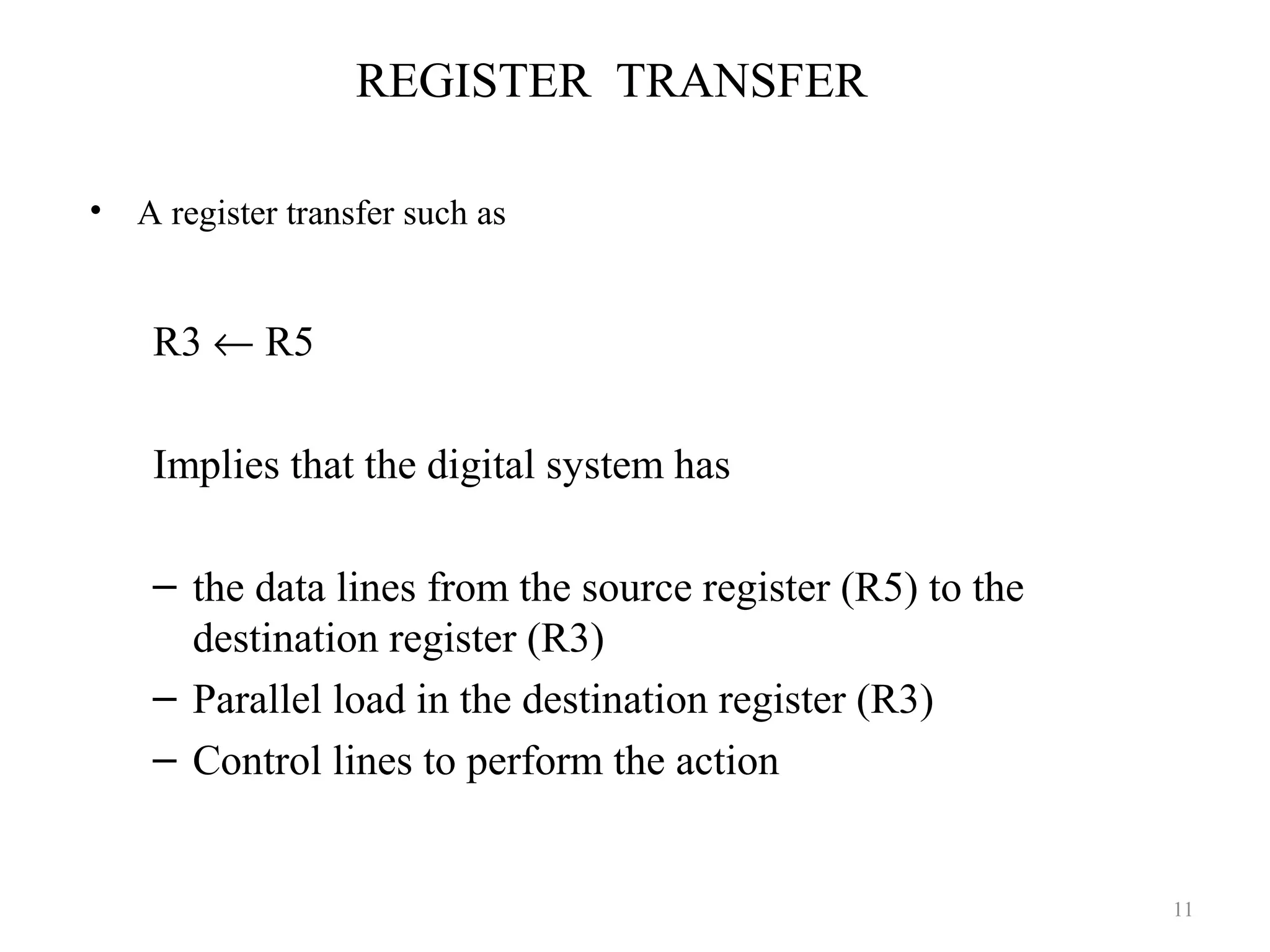


![Memory Transfer
MBR ← M
MBR ← M [ R1 ]
30 /](https://image.slidesharecdn.com/mca-i-u-2-overviewofregistertransfermicrooperationsandbasiccomputerorganizationanddesign-150121231801-conversion-gate02/75/Mca-i-u-2-overview-of-register-transfer-micro-operations-and-basic-computer-organization-and-design-30-2048.jpg)
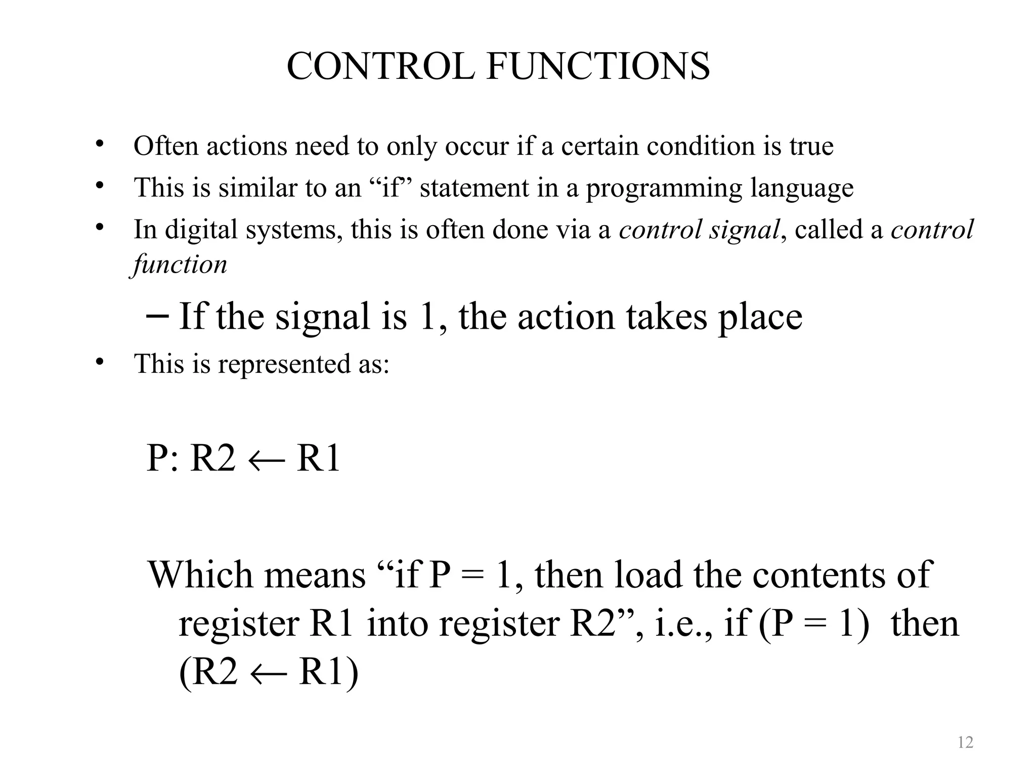
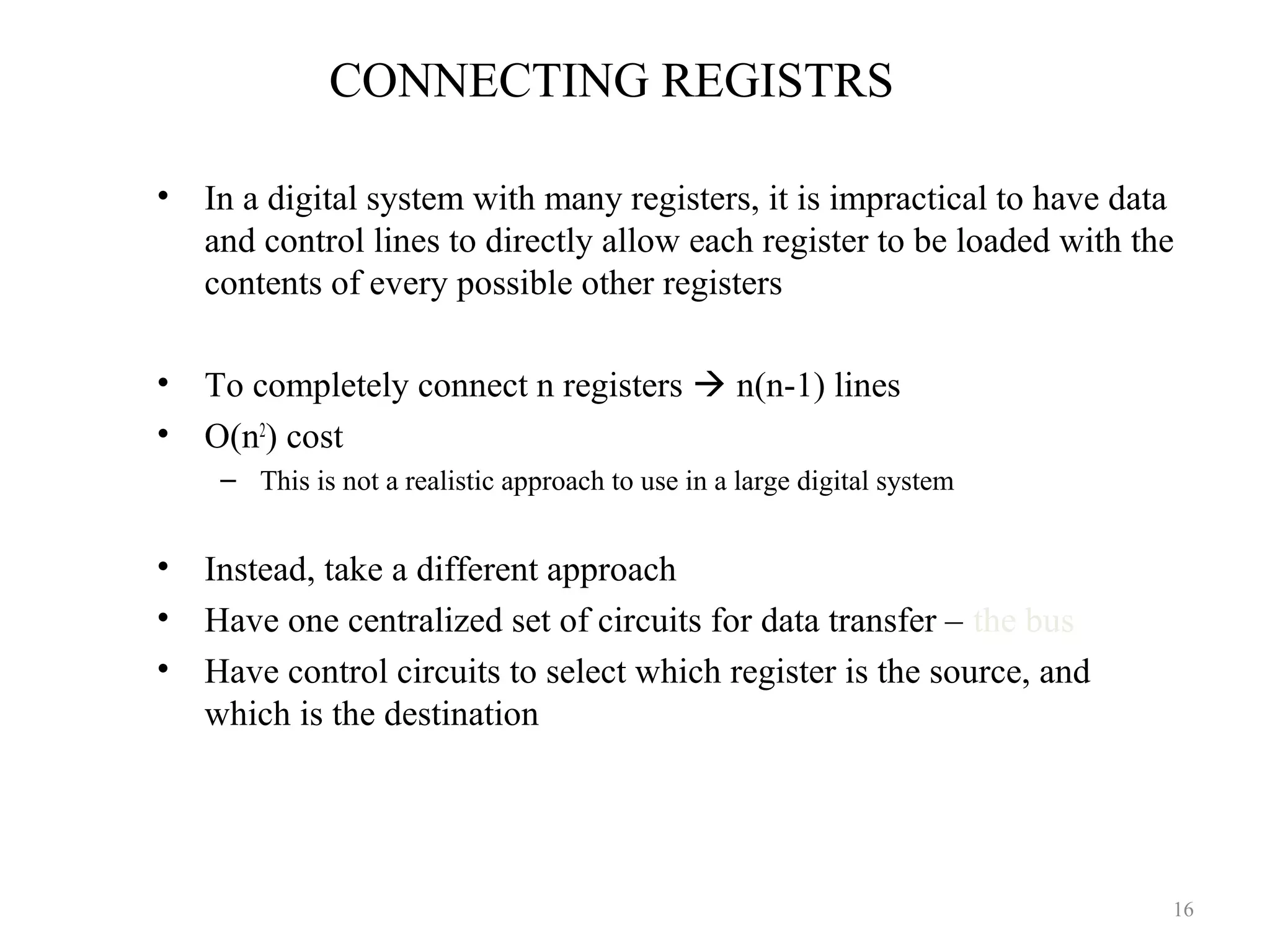
![Micro-Operation Summary
31 /
Symbolic Description
A ← B Transfer content of register B into register A
MAR ← MBR(AD) Transfer content of AD portion of register MBR into MAR
A ← Constant Transfer binary (code) constant into register A
ABUS ← R1
R2 ← ABUS
Transfer content of R1 into bus A and at the same time transfer
content of bus A into R2
MAR Memory address register: holds the address of the memory unit
MBR
Memory buffer register: holds the data transferred in or out of the
memory
M [ R ]
Denotes the memory word specified by the address presently
available in register R
M
Denotes the memory word specified by the address in an implied
register MAR
MBR ← M Memory read operation
M ← MBR Memory write operation](https://image.slidesharecdn.com/mca-i-u-2-overviewofregistertransfermicrooperationsandbasiccomputerorganizationanddesign-150121231801-conversion-gate02/75/Mca-i-u-2-overview-of-register-transfer-micro-operations-and-basic-computer-organization-and-design-31-2048.jpg)
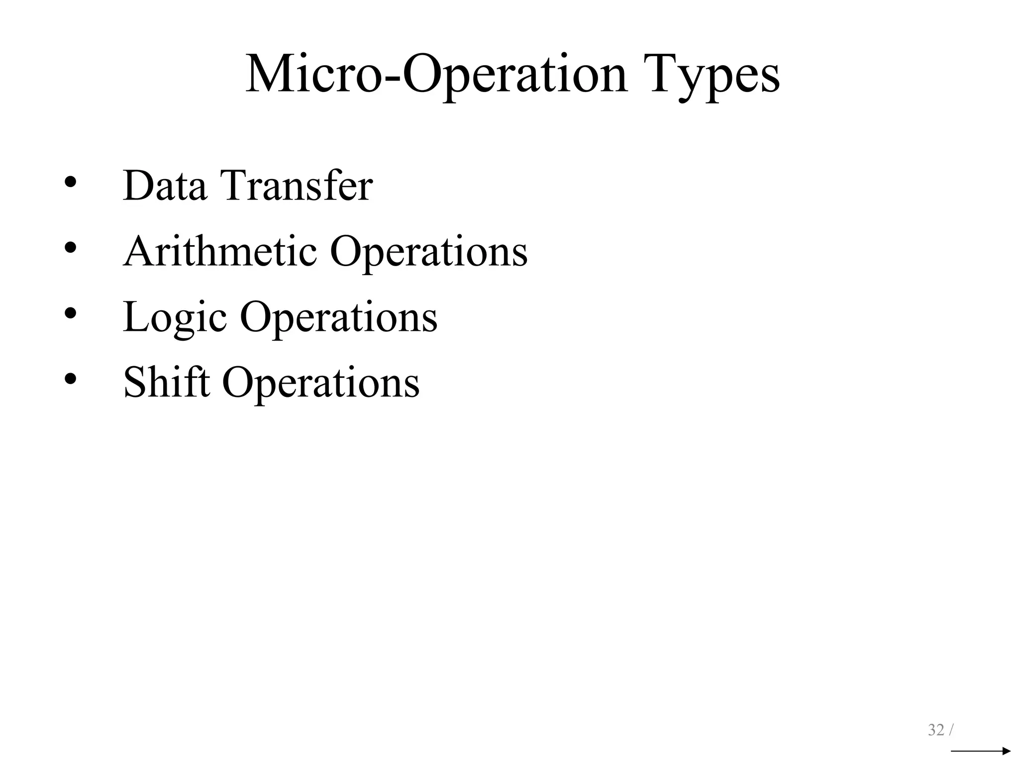
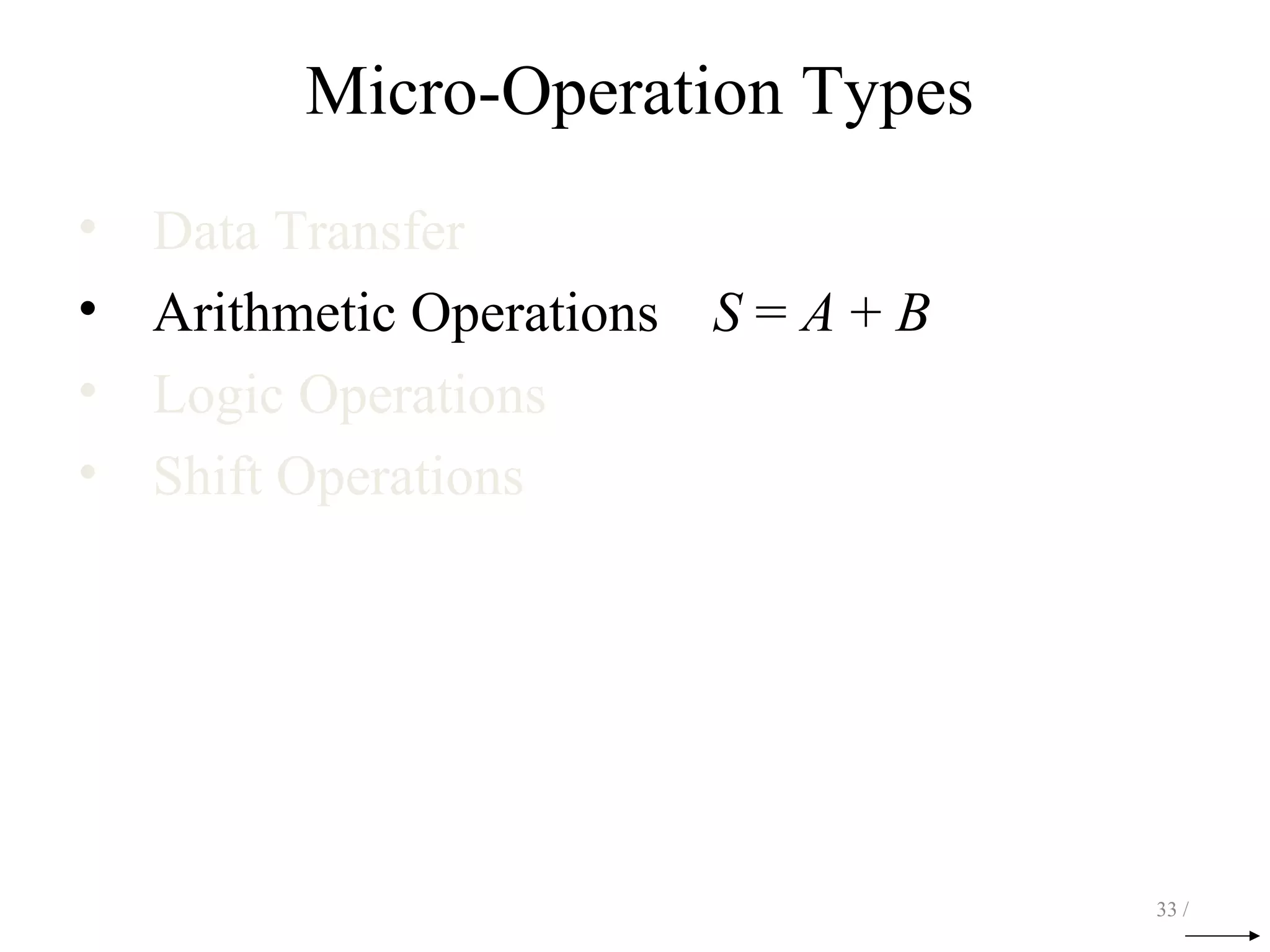


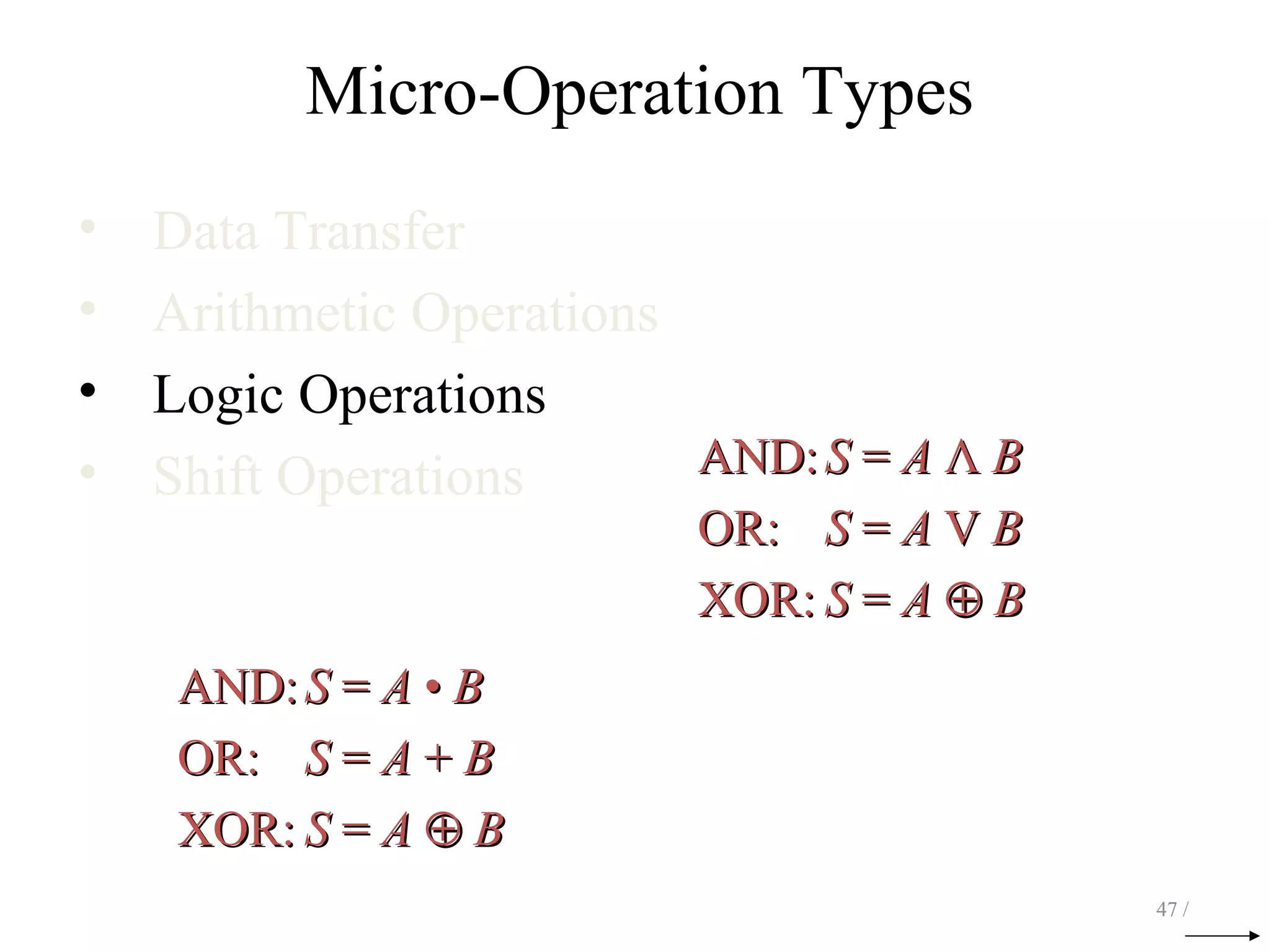


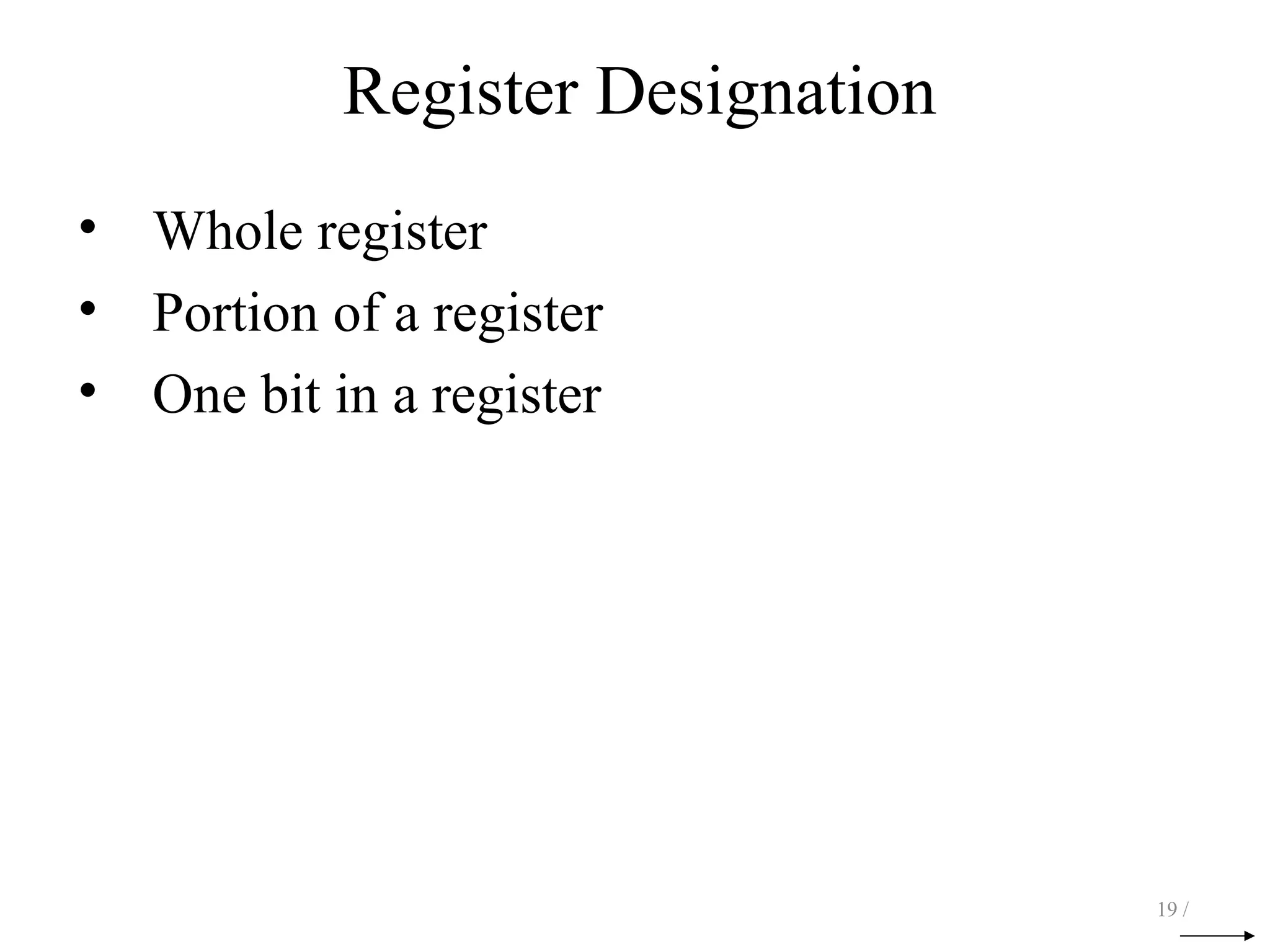
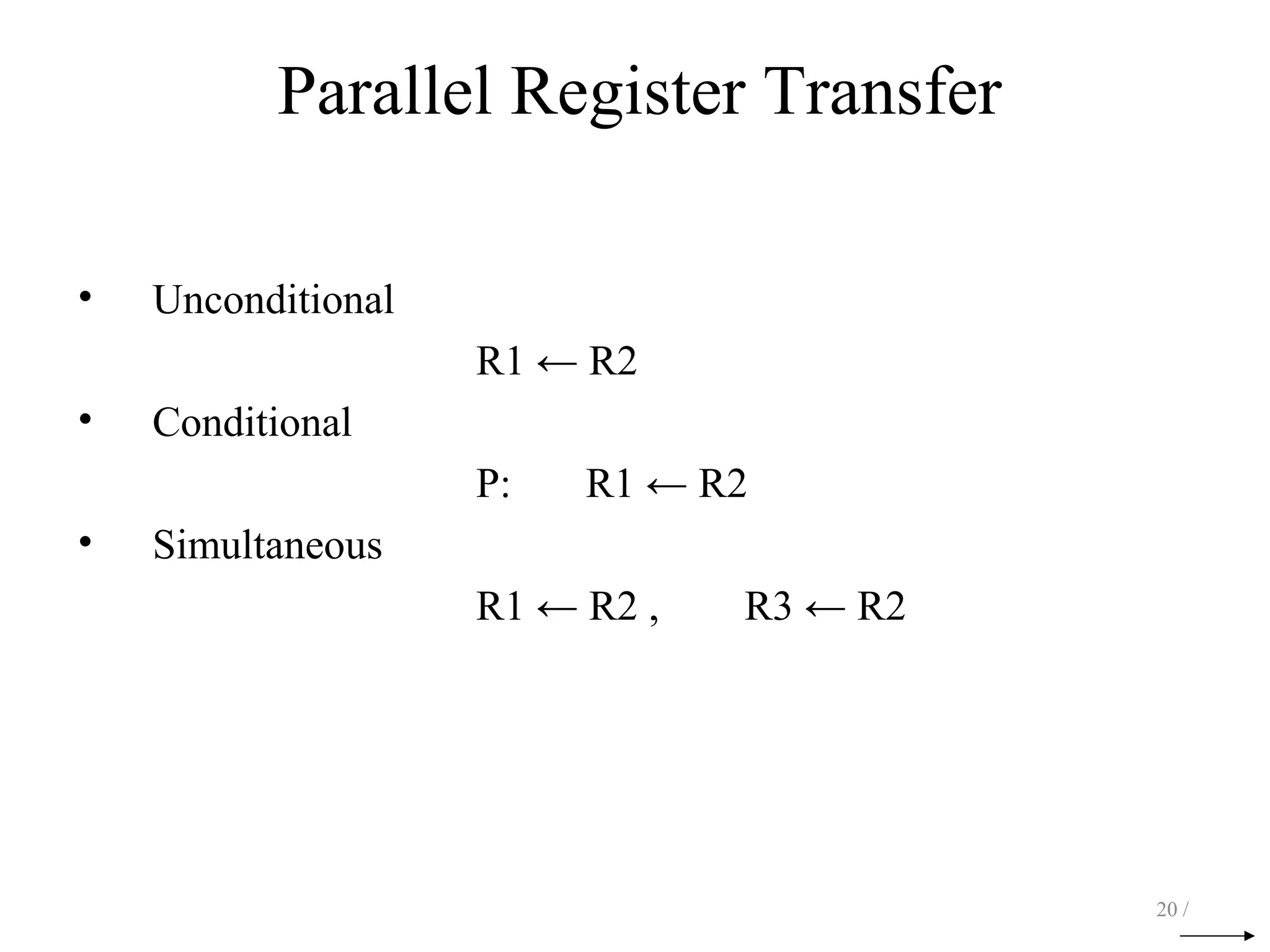
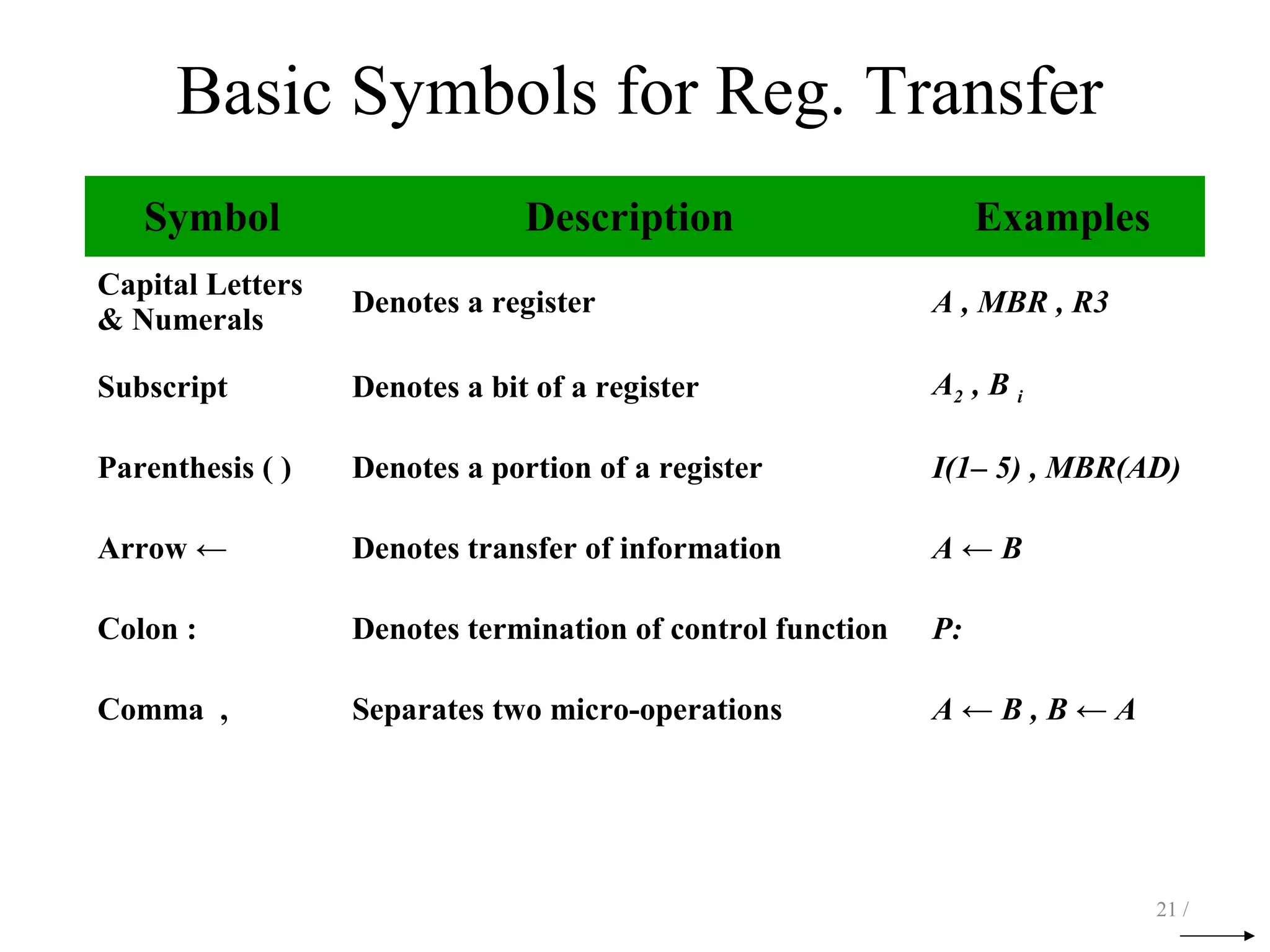
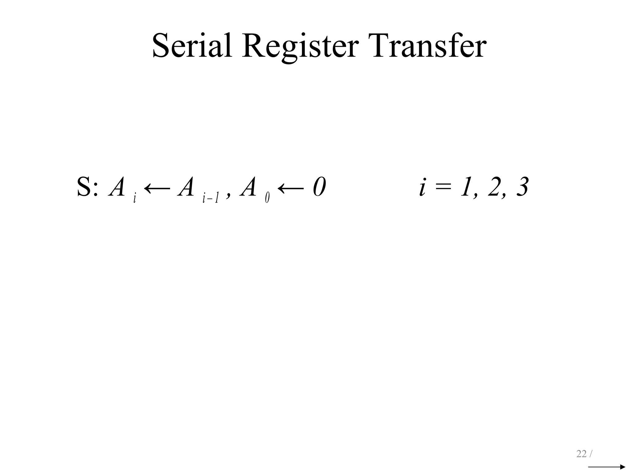
This document provides an overview of register transfer, micro-operations, and basic computer organization and design. It discusses how digital systems can be characterized by their registers and operations. Micro-operations are the elementary operations performed on register data during each clock cycle. A computer's organization is defined by its registers, micro-operation set, and control signals. Registers are designated symbolically and bits can be individually referenced. Basic register transfer operations involve copying data between registers, which can be unconditional or conditional. Common micro-operation types include data transfer, arithmetic, logic, and shift operations.