Downloaded 193 times
![Intermodulation
Intermodulation(IMD) distortion is the result of two signals interacting in a
nonlinear device to produce additional unwanted signals. These IMDs occur
mainly in devices such as amplifiers and mixers[3,7]
Even if these IMDs are not exactly located at the signal frequency in spectrum,
they are still able to interfere signal.
1](https://image.slidesharecdn.com/reverseimd-151013153117-lva1-app6892/85/Reverse-IMD-1-320.jpg)
![Intermodulation
Intermodulation(IMD) distortion is the result of two signals interacting in a
nonlinear device to produce additional unwanted signals. These IMDs occur
mainly in devices such as amplifiers and mixers[3,7]
Even if these IMDs are not exactly located at the signal frequency in spectrum,
they are still able to interfere signal.
1](https://image.slidesharecdn.com/reverseimd-151013153117-lva1-app6892/75/Reverse-IMD-1-2048.jpg)
![As shown in the figure above, fa and fb generate IMD3. In terms of Fourier
transform, IMD is a product in the time domain, and which is also a convolution
in the frequency domain[5] , i.e.,
Thus, the IMD3 product at (2f a − f b) has a bandwidth of (2fa + fb), and the IMD3
at (2f b − f a) has a bandwidth of (2fb + fa). Therefore, these IMDs may cover a lot
of channels, higher the order of IMD, wider the bandwidth of IMD.
That is to say, as long as these IMDs are near signal and have wide enough
bandwidth, they are still able to interfere signal without being located at the
same frequency as which of signal.
2](https://image.slidesharecdn.com/reverseimd-151013153117-lva1-app6892/85/Reverse-IMD-2-320.jpg)
![In addition, they also occur in passive devices such as those found in many
transmission systems. For example, RF connectors on transmission feeds may
become corroded over time resulting in them behaving as nonlinear diode
junctions[3].
As illustrated in the figure above, the I-V curve of diode is typically nonlinear. As a
result, we may see unwanted nonlinear frequency responses of passive
components including connectors and cable feeds[8,9].
3](https://image.slidesharecdn.com/reverseimd-151013153117-lva1-app6892/85/Reverse-IMD-3-320.jpg)
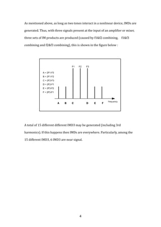
![For example, there is Tx leakage issue in WCDMA, CDMA, and FDD-LTE[6,10] :
Therefore, there will be three signals in the receiver input : Blocker, Rx signal,
and Tx signal :
As illustrated above, there will be 15 different IMD3, and 6 of which are near Rx
signal.
5](https://image.slidesharecdn.com/reverseimd-151013153117-lva1-app6892/85/Reverse-IMD-5-320.jpg)
![Reverse Intermodulation
As for base stations, if their antennas are placed relatively close together[5],
the IMDs are more considerable[8].
6](https://image.slidesharecdn.com/reverseimd-151013153117-lva1-app6892/85/Reverse-IMD-6-320.jpg)
![What mentioned above is forward IMD. In fact, there is still reverse IMD(RIM).
All these IMDs(including both forward IMD and RIM) have a debilitating effect
on the performance of telecommunications networks. The result decreases
system capacity and degrades call quality at cell sites[3].
So, what’s RIM ? Let’s take PA for example. A single PA where two tones are
present at the input, and IMDs are produced in the normal way, as illustrated
below[1,5] :
Nevertheless, because the isolation between these tones is not perfect, then a
reverse interference is fed from one amplifier to another. The reverse signal
interacts with the transmission signal causing RIMs to be broadcast, which could
then interfere with other systems[1,5].
7](https://image.slidesharecdn.com/reverseimd-151013153117-lva1-app6892/85/Reverse-IMD-7-320.jpg)
![Spectrum of RIM is illustrated as below[4] :
Therefore, some PA datasheets have RIMs test results, e.g. RF3267 of RFMD[2].
Nevertheless, all IMDs, regardless of forward or reverse form, can cause
interference at a receiver[5].
8](https://image.slidesharecdn.com/reverseimd-151013153117-lva1-app6892/85/Reverse-IMD-8-320.jpg)
![As illustrated in the figure above, large transmit signal b from jammer B radiates
into the power amplifier of jammer A and produces IMD3 that may fall in the
desired receive channel of a colocated base station receiver RX.
Particularly, compared to PA, LNA is susceptible to saturation. In other words, the
IMDs do not fall directly on the desired receive channel, the high power jamming
signals at the victim receiver may still saturate the receiver front-end and cause
desensitization regardless of their frequencies[5].
As illustrated in the figure below[36], the gain of LNA reduces if the blocker is at
LNA input with large enough level and regardless of its frequency[36].
9](https://image.slidesharecdn.com/reverseimd-151013153117-lva1-app6892/85/Reverse-IMD-9-320.jpg)
![As illustrated in the figure below, desired signal at 920MHz, blocker at 921MHz.
They are not located at the same frequency, but the blocker still has
overwhelmed the LNA, and desensitized its gain by 17dB[5].
10](https://image.slidesharecdn.com/reverseimd-151013153117-lva1-app6892/85/Reverse-IMD-10-320.jpg)
![As mentioned above, receivers need to have minimized IMDs to maintain call
quality[3]. Thus, the receiver pre-filtering stops large outband jamming signals
and admits only the desired signal into the LNA, even if the method degrades
sensitivity due to insertion loss of pre-filter[10], as illustrated below[5] :
Likewise, transmitter post-filtering rejects any reverse signal from entering the
PAs and stops IMDs from being transmitted, even if the method increases PA
post-loss and forces PA to generate more output power with the same target
power, as illustrated in the figure above[5].
Besides, some receivers integrate cancellation system carried out by DSP[5].
11](https://image.slidesharecdn.com/reverseimd-151013153117-lva1-app6892/85/Reverse-IMD-11-320.jpg)
![Reference
[1] CMOS RF POWER AMPLIFIERS FOR MOBILE WIRELESS COMMUNICATIONS
[2] RF3267, 3V W-CDMA LINEAR PA MODULE, RFMD
[3] Intermodulation Distortion, Application Note, AEROFLEX
[4] Sensitivity and Mitigation of Reverse IMD in Power Amplifiers
[5] INTERFERENCE MITIGATION IN COLOCATED WIRELESS SYSTEMS
[6] A Highly Selective, Very Linear Low Noise Transconductance Amplifier
Capable of Large-Signal Handling for Current-Mode Receivers Front-End
[7] Understanding Intermodulation Distortion Measurements
[8] Passive Intermodulation (PIM) in the RF Path
[9] Maximizing Network Capacity by Minimizing Passive Intermodulation (PIM)
[10] Sensitivity or selectivity -- How does eLNA impact the receriver
performance, Slideshare
12](https://image.slidesharecdn.com/reverseimd-151013153117-lva1-app6892/85/Reverse-IMD-12-320.jpg)

Intermodulation distortion (IMD) occurs when two or more signals interact in a nonlinear device, producing unwanted signals at frequencies that are not found at the input. IMD can interfere with signals even if they are not at the same frequency. Common sources of IMD include amplifiers, mixers, and corroded connectors. Higher order IMDs have wider bandwidth, so they can interfere with more channels. Both forward and reverse IMD can degrade network performance and call quality at cell sites. Receiver filtering and transmitter filtering can help mitigate IMD effects.


![射頻電子 - [第六章] 低雜訊放大器設計](https://cdn.slidesharecdn.com/ss_thumbnails/ch6-150613065106-lva1-app6892-thumbnail.jpg?width=640&height=640&fit=bounds)


![Lecture 1 Communication Systems[2886].pptx](https://cdn.slidesharecdn.com/ss_thumbnails/lecture1communicationsystems2886-250223172317-0af739f2-thumbnail.jpg?width=640&height=640&fit=bounds)