Download as PDF, PPTX
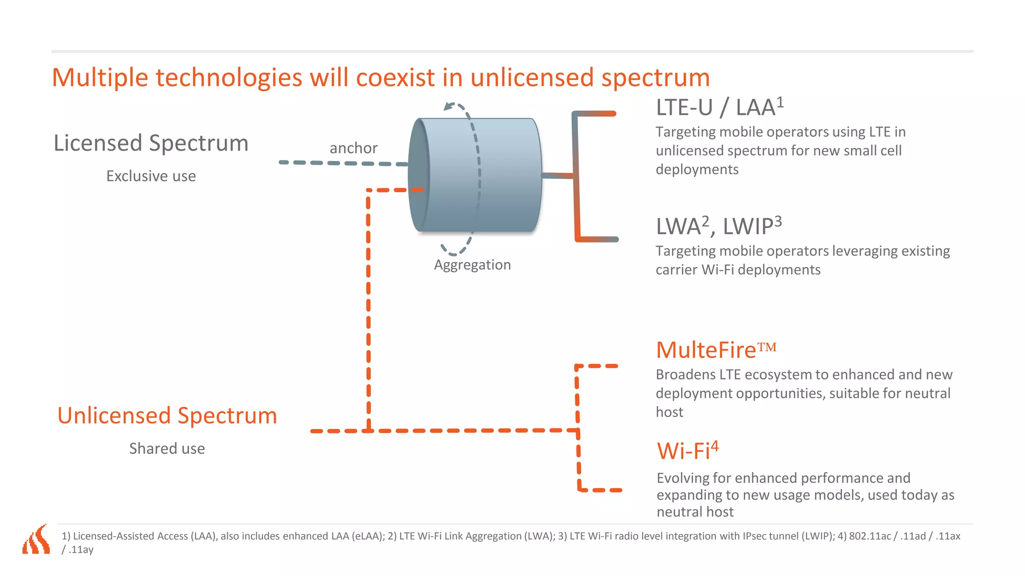
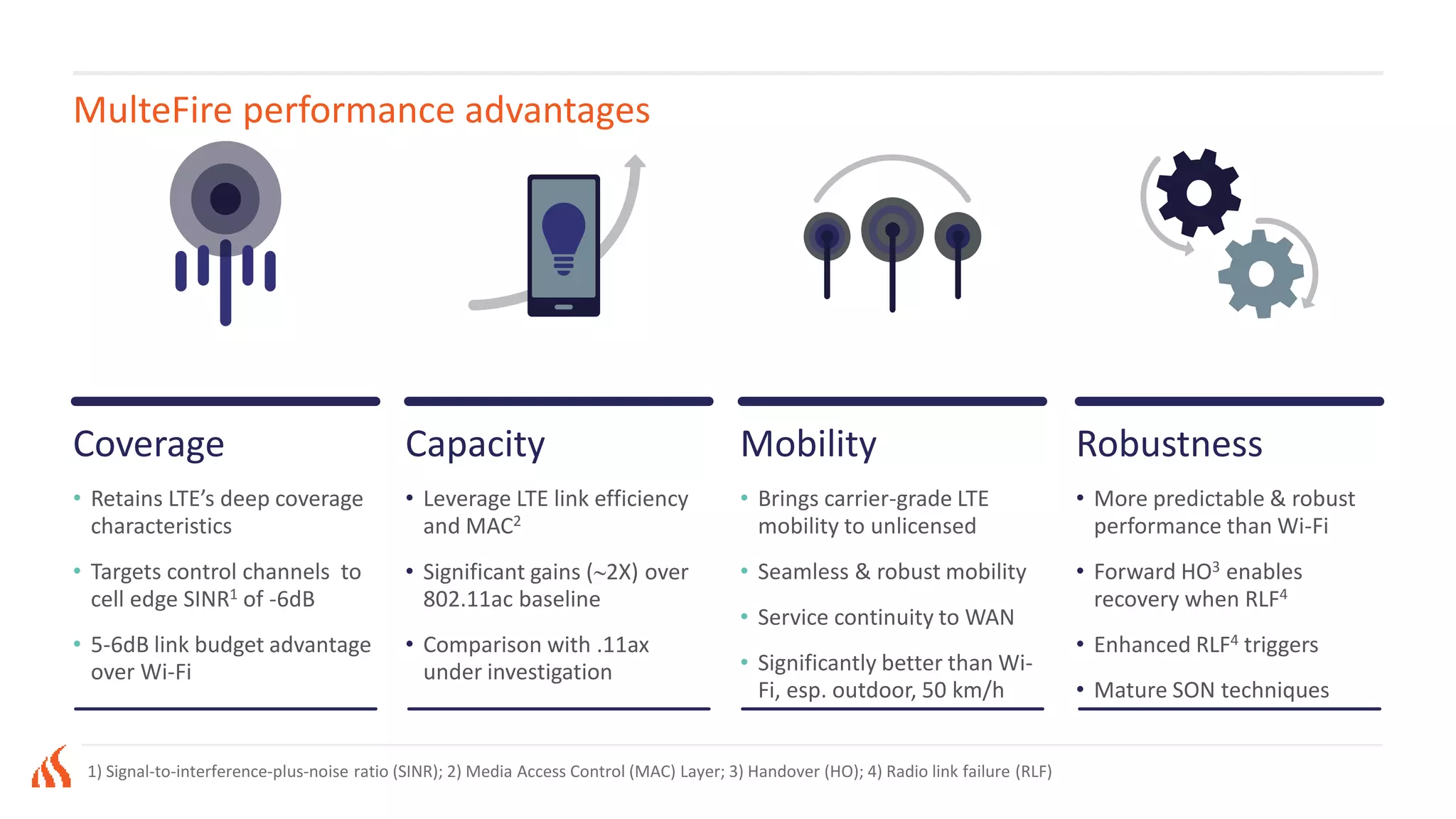
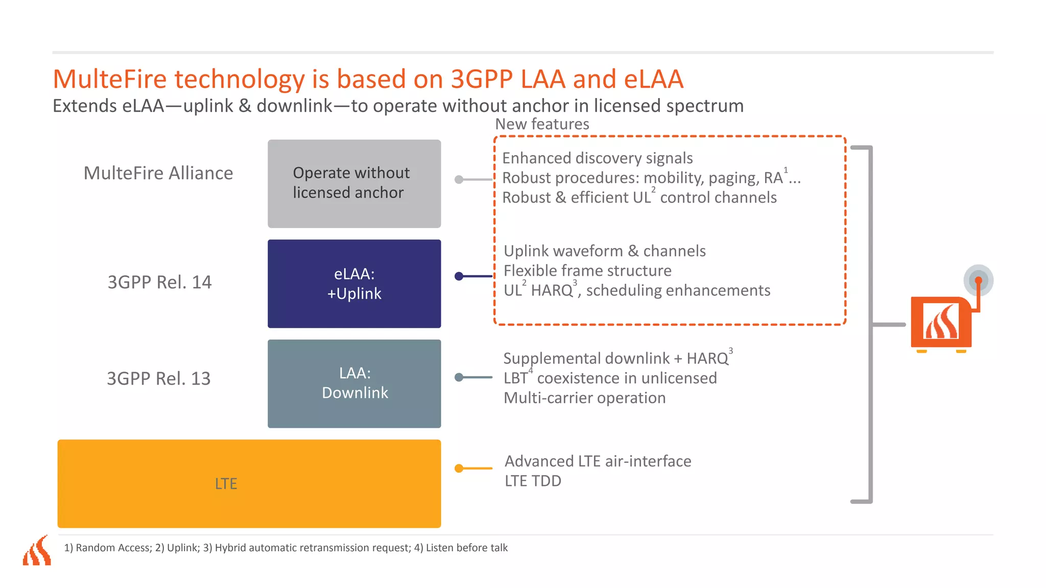
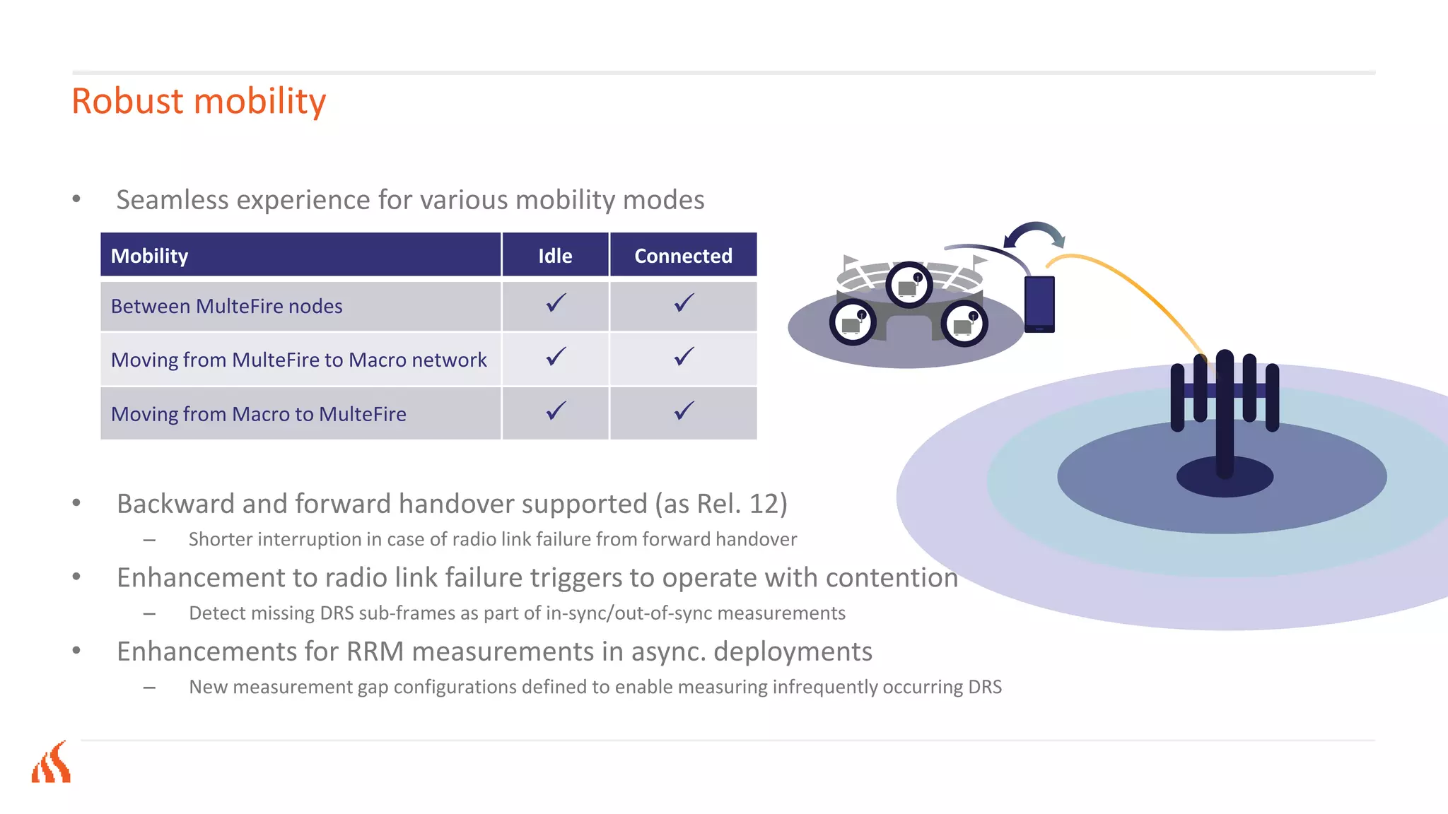
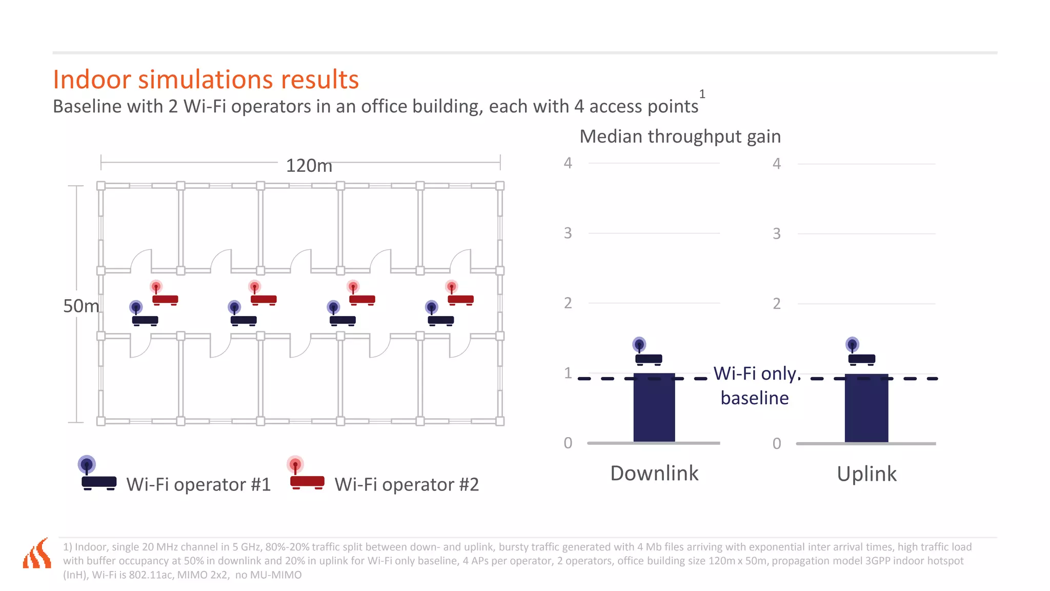
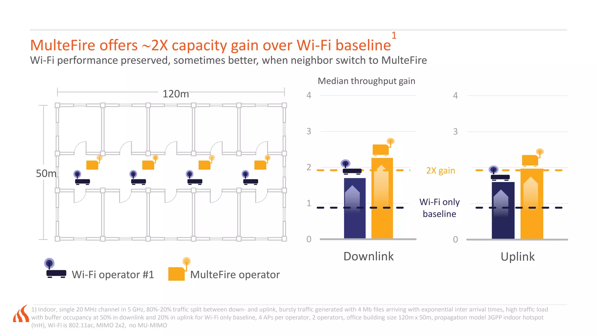
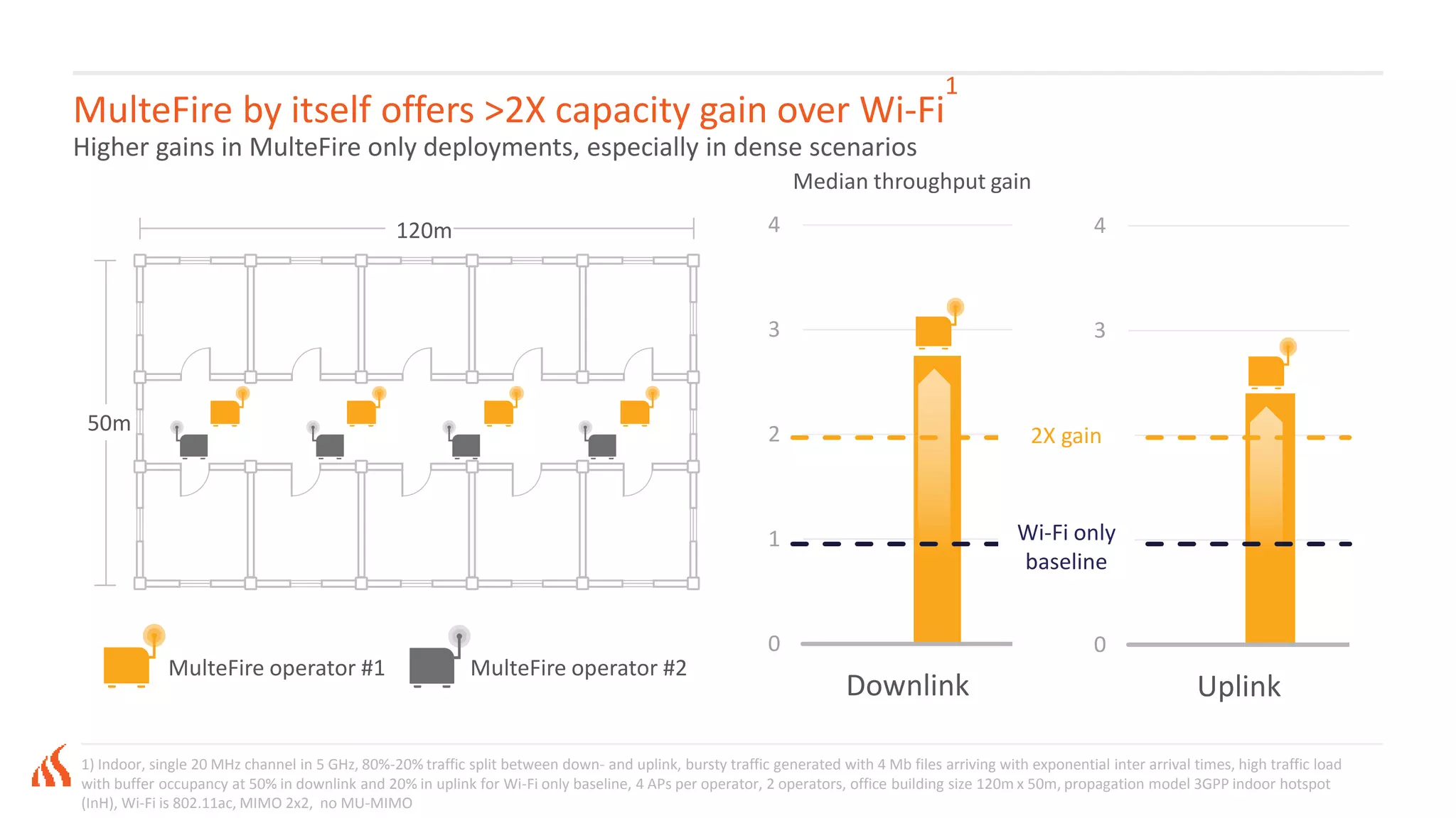
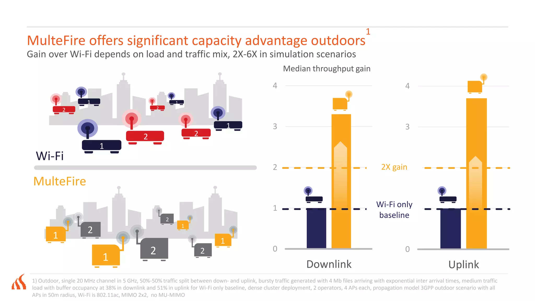

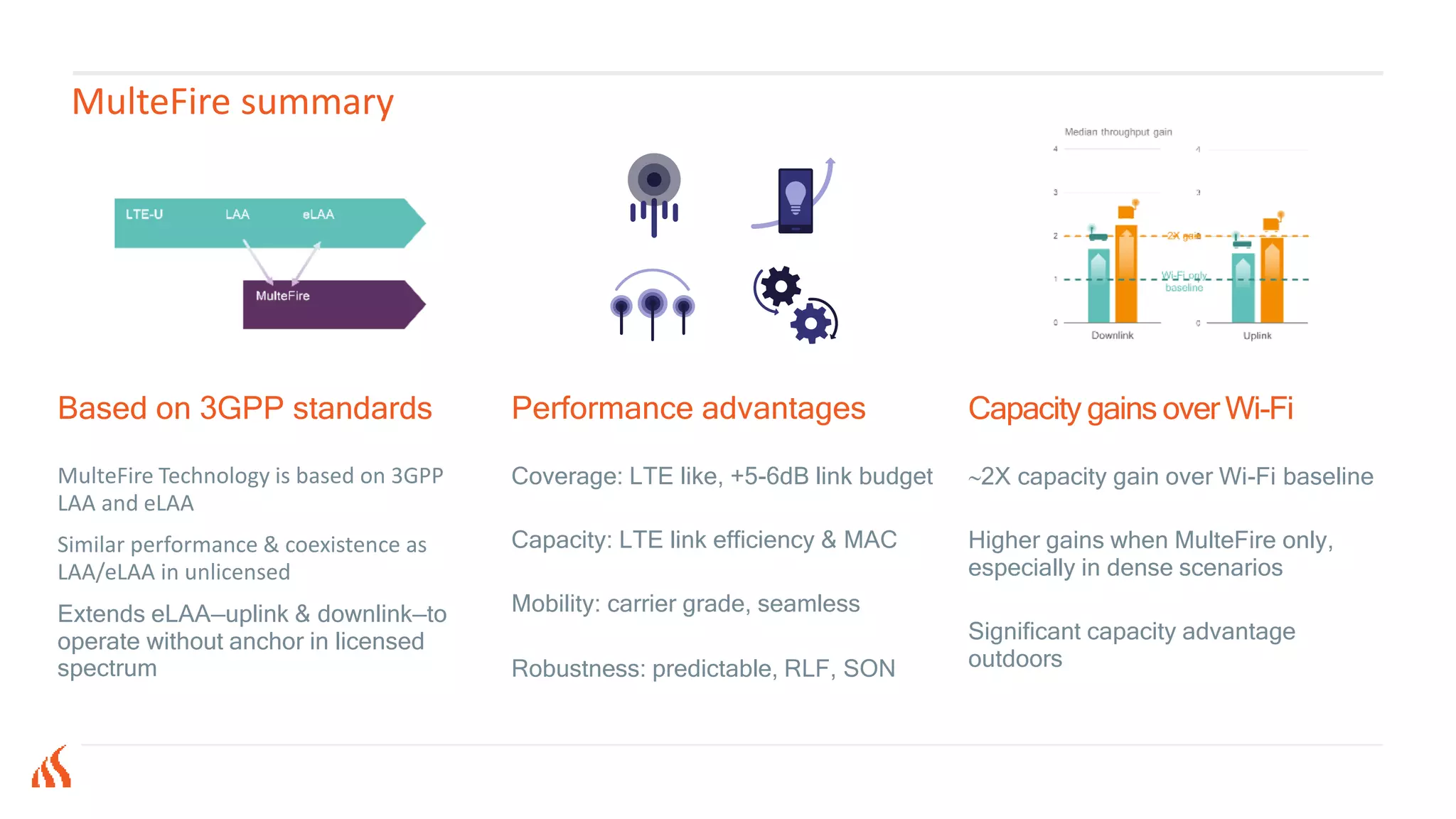


Multefire technology enhances LTE performance by enabling operation in unlicensed spectrum while maintaining strong coverage, capacity, and mobility benefits. It coexists with existing technologies such as LAA and ELAA, offering approximately double the capacity compared to Wi-Fi under similar conditions. Key advantages include improved signal quality, seamless mobility, and efficient resource management, particularly in dense environments.