Download to read offline


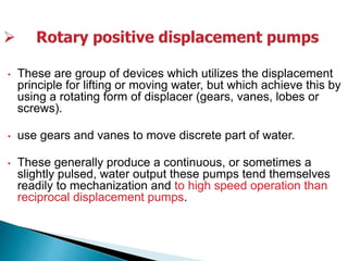


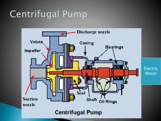


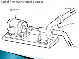


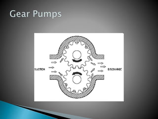
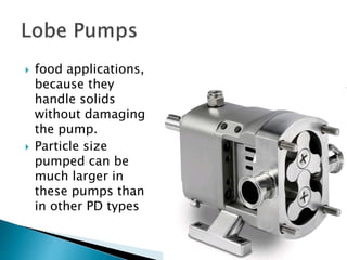


The document discusses various types of pumping systems including their components and operating principles. It describes reciprocating pumps which use back-and-forth motion to displace water, rotary pumps which use gears or vanes for displacement, and centrifugal pumps which use the centrifugal force of an impeller to increase pressure and flow. Specific types like volute and turbine centrifugal pumps are mentioned. Cavitation and net positive suction head are also discussed as important considerations for pump selection and performance.


![2938 [autosaved]](https://cdn.slidesharecdn.com/ss_thumbnails/2938autosaved-141224115226-conversion-gate02-thumbnail.jpg?width=640&height=640&fit=bounds)


