A fluid machineis a device which converts
the energy stored by a fluid into
mechanical energy or vice versa . The
energy stored by a fluid mass appears in
the form of potential, kinetic and
intermolecular energy. The mechanical
energy, on the other hand, is usually
transmitted by a rotating shaft. Machines
using liquid (mainly water, for almost all
practical purposes) are termed as hydraulic
machines.
4.
The device inwhich the kinetic, potential or
intermolecular energy held by the fluid is converted
in the form of mechanical energy of a rotating
member is known as a turbine .
The machines, on the other hand, where the
mechanical energy from moving parts is transferred
to a fluid to increase its stored energy by increasing
either its pressure or velocity are known as pumps,
compressors, fans or blowers .
6.
The machines whosefunctioning depend essentially on the
change of volume of a certain amount of fluid within the
machine are known as positive displacement machines .
The word positive displacement comes from the fact that
there is a physical displacement of the boundary of a
certain fluid mass as a closed system. This principle is
utilized in practice by the reciprocating motion of a piston
within a cylinder while entrapping a certain amount of fluid
in it.
Therefore, the word reciprocating is commonly used with
the name of the machines of this kind. The machine
producing mechanical energy is known as reciprocating
engine while the machine developing energy of the fluid
from the mechanical energy is known as reciprocating
pump or reciprocating compressor.
9.
The machines, functioningof which depend basically on the principle of
fluid dynamics, are known as rotodynamic machines . They are
distinguished from positive displacement machines in requiring relative
motion between the fluid and the moving part of the machine.
The rotating element of the machine usually consisting of a number of
vanes or blades, is known as rotor or impeller while the fixed part is
known as stator. Impeller is the heart of rotodynamic machines, within
which a change of angular momentum of fluid occurs imparting torque
to the rotating member.
10.
• Pump: Whena fluid has to be "moved" in a system, pumps are used. The
pump is a machine which has the function of increasing the total energy of
a liquid; this means that the pump transfers energy to the fluid that it
receives from the driving motor”.
Need of a Pump:
Used to pump a liquid from lower pressure area to a High pressure area.
To increase Flow rate.
To move liquid from lower elevation to higher elevation.
Displacement Vs Centrifugal
Centrifugal pumps are suitable for low head and high flow rate.
PD pumps produce high head and low flow rate.
PD are suitable for High Viscosity application.
Centrifugal Pumps are not recommended for high viscosity
application because as viscosity increases its flow decreases.
Usually a relieve valve is attached with the displacement
pumps.
16.
CLASSIFICATION
According toworking head
According to casing
According to number of entrances to the impeller
According to types of impeller
According to number of stages
According to shape of the vanes
According to disposition of shaft
17.
According toworking head
Low head centrifugal pump – working head developed by
these pumps is up to 15m.
Medium head centrifugal pump – working head developed
by these system is 15m<H<45m.
High head centrifugal pump – working head developed by
these pumps is more than 45m.
18.
• Volute Casing
•In this casing, the impeller is
surrounded by the spiral casing.
• The casing is such shaped that
it’s casing area gradually increases
from tongue to delivery pipe.
• Due to impact of the high
velocity water leaving the impeller
(shock losses), efficiency of
conversion of K.E. into P.E. is
very less.
According to casing
19.
• Vortex Casing
•In this casing, an annular space
known as vortex or whirlpool
chamber is provided between the
impeller and volute casing.
• Liquid from the impeller flow
with free vortex motion in vortex
chamber where it’s velocity is
converted into pressure energy.
• It is more efficient than a volute
casing.
20.
• Diffuser Casing
•In this casing , the guide vanes
are arranged at the outlet of the
impeller.
• The guide vanes are shaped to
provide gradually enlarged
passage for flow of liquid.
• The kinetic energy of the liquid
coming out from the impeller is
converted into the pressure
energy during flow in guide
vanes (increasing area).
21.
According tonumber of
entrances to the impeller
• Single suction pump
Liquid enters from a
suction pipe to impeller
only from one side.
• Double suction pump
Liquid enters to both the
sides of impeller.
22.
According to typesof impeller
• Closed impeller
if the vanes of the impeller
are covered with plates on
both sides, it is called a
closed impeller. It is made
of cast iron, stainless steel,
cast steel, gun metal.
23.
• Semi openimpeller
if the vanes of the
impeller are covered
with plate on one side, it
is called semi open
impeller. It has less
number of vanes, but it’s
height is more than that
of closed impeller.
24.
• Open impeller
Ifthe vanes of the
impeller are without
covered plate, it is called
open impeller. These are
generally made of forged
steel. It has less life, as
they have to perform
very rough task.
25.
According to numberof stage
• Single stage
In a single stage pump, only
one impeller is used on the
shaft.
Multi stage
In a multi stage pump, more
than one impeller is used on
the same shaft and enclosed
in the same casing. It is
used to raise high head.
26.
According to shapeof the vanes
• Curved forward vanes
The outlet tip of the vane
is curved forward in the
direction of rotation of the
impeller. The impeller
having such vanes is
called slow speed
impeller. This type of the
impeller has low
efficiency about 75%.
27.
• Radial vanes
Thesevanes have outlet tips
in radial direction. The
impeller having such vanes
is called medium speed
impeller. The efficiency of
this type of impeller varies
from 80% to 85%.
28.
• Curved backwardvanes
The outlet tip of the vane is
curved backward in the
direction of rotation of the
impeller. The impeller
having such vanes is
called fast speed impeller.
This type of impeller
gives highest efficiency
about 85% to 90%.
29.
According todisposition of the shaft
• Horizontal pump • Vertical pump
In this type of pump, the
impeller shaft is used
horizontal.
In this type of pump, the
impeller shaft is used
vertical.
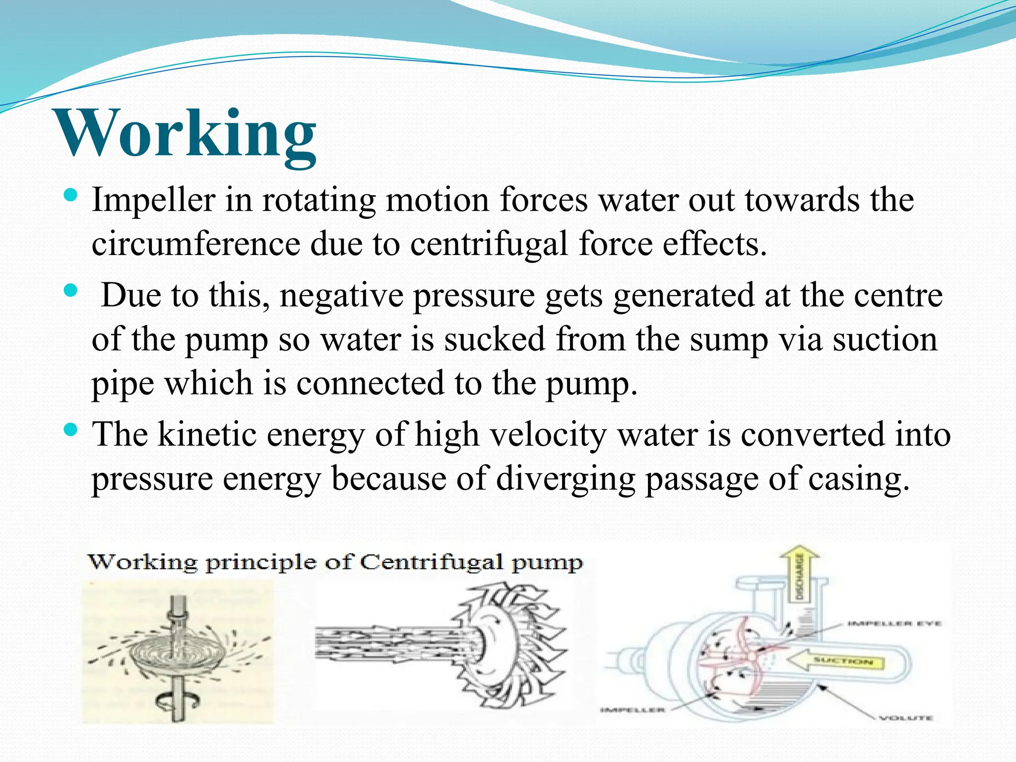
Working
Impeller inrotating motion forces water out towards the
circumference due to centrifugal force effects.
Due to this, negative pressure gets generated at the centre
of the pump so water is sucked from the sump via suction
pipe which is connected to the pump.
The kinetic energy of high velocity water is converted into
pressure energy because of diverging passage of casing.
39.
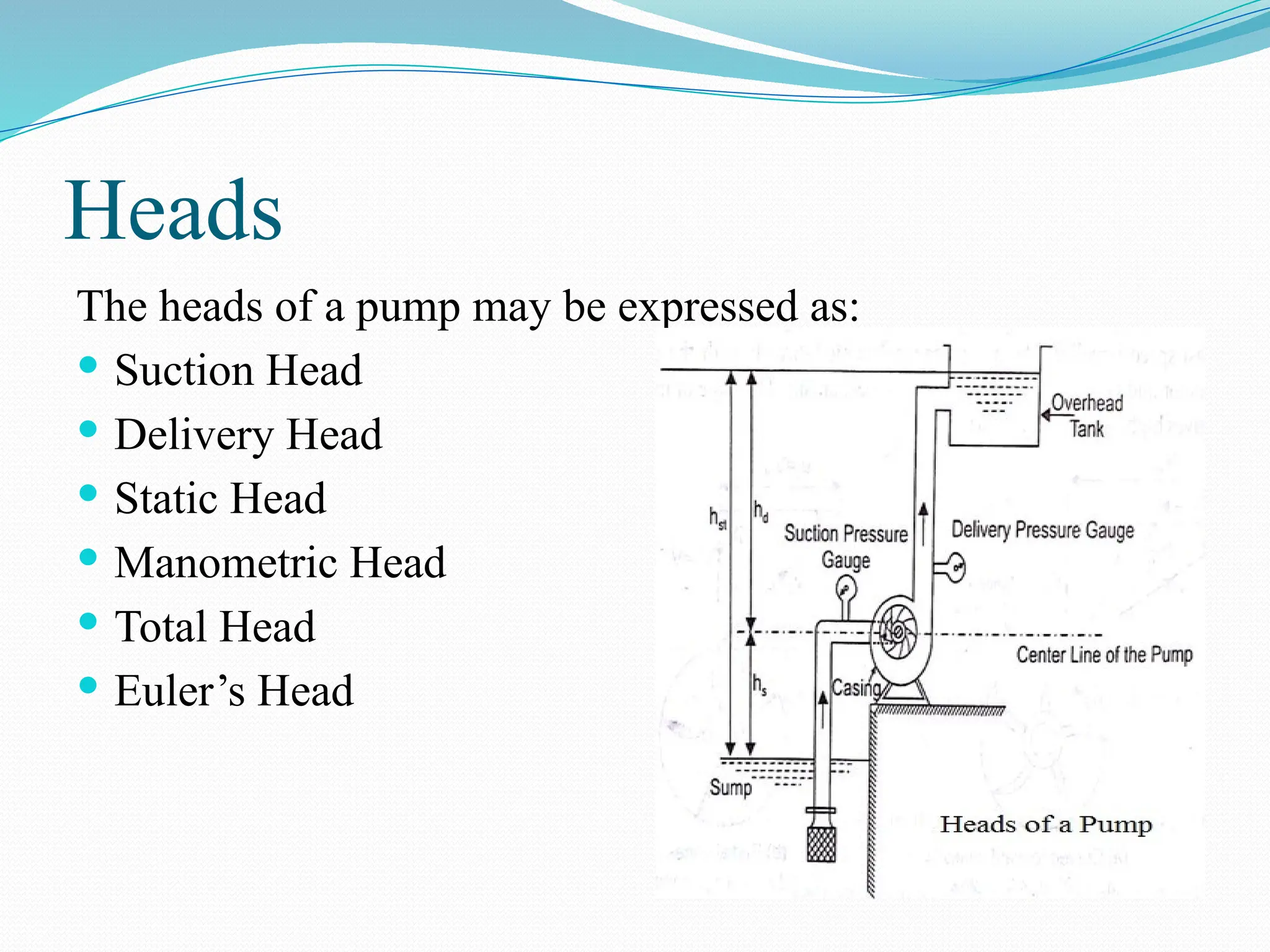
Heads
The heads ofa pump may be expressed as:
Suction Head
Delivery Head
Static Head
Manometric Head
Total Head
Euler’s Head
40.
Suction Head(hs): It is the vertical distance b/w liquid levels
in the sump and the centre line of the pump. Usually, it is
kept 7 to 8 m to avoid cavitation.
Delivery Head (hd): It is the vertical height of the liquid
surface in the overhead tank to which the liquid is delivered
above the centre line of the pump.
Static Head (hst): It is the vertical distance b/w liquid levels
in the sump and the overhead tank. It is the sum of suction
head and delivery head. (hst=hs+hd).
Manometric Head (Hm): The available head against which a
centrifugal pump has to work is known as the monomeric
Head.
Total Head (H): It is the total head which has to be
developed by a pump to deliver the liquid from the sump
into the overhead tank.
41.
Euler’s Head(He): It is defined as the head developed by
the impeller. It is denoted as He.
Losses
Energy losses in centrifugal pumps may be classified as
follows:
a. Hydraulic Losses
b. Mechanical losses
c. Leakage Losses`
42.
Hydraulic Losses:There are two types of hydraulic
losses which may occur in a pump.
a. Pipeline Losses: Major (due to friction) and minor (due
to pipe bend) losses in pipes.
b. Pump Losses: Eddy or shock losses, frictional losses in
impeller, guide vane/diffuser, casing.
Mechanical Losses: Losses due to friction of main
bearings and glands.
Leakage Losses: slipping back of part of liquid through
the clearance between the impeller and casing due to
pressure difference b/w inlet and outlet. Energy carried
by these liquid is ultimately wasted and this loss of
energy of liquid is known as leakage losses.
43.
Advantages
Small insize & space saving.
Output is very steady and consistent.
Easy for maintenance.
No danger creates if discharge valve is closed while
starting.
Deal with large volume.
Able to work on medium to low head.
Able to work on medium to low viscous fluid.
Almost no noise
44.
Disadvantages
Extra primingprocess requires.
Cannot be able to work on high speeds.
Cannot deal with highly viscous liquid.
Application
• Agriculture and irrigation purpose.
• Pumping of water in buildings.
• Transfer raw material.
49.
Cavitation can betermed as
“the heart attack of the pump”.
The formation and collapse of vapor bubbles in a liquid.
Mechanism of Cavitation
•The phenomenon of cavitation is
summarized as follows:
•1- Formation of bubbles inside the
liquid being pumped.
•2-Growth of bubbles
•3- Collapse of bubbles
Cavitation
The formation of bubble occurs at
point where the pressure is less than
the vapor pressure, and bubble
collapse occurs at a point where the
pressure is increased to the vapor
pressure.
CAVITATION
54.
Collapse of vaporbubble suddenly
change its phase from vapor to liquid at
very high velocity which impact shock
wave on the surface of the impeller
which can reach a value around 12000
Psi .This pressure capable to deform the
metal of the pump creating pitting. It is
important to remember that , this
process IS NOT ONE TIME EVENT ,it
will be repeated 2400 time each
minutes this may lead to erode the
metal and damage the pump.
55.
Symptoms of Cavitation
Cavitationin pumps can often be detected by
a characteristic generated sound. It sounds
like gravel in a concrete mixer.
Cavitation lead to excessive vibration, fatigue
and greatly increased wear of pump parts
such as bearing failures , sealing leakage ,
Metal gets corroded seen as small pitting's.
Cavitation Loss in pump performance
reduces the flow rate , head & efficiency of the
pump & life time.
57.
Net Positive SuctionHead Available
(N.P.S.H.A.) The Net-Positive Suction
Head Available (N.P.S.H.A.) is the total
energy per unit weight, or head, at the
suction flange of the pump minus the
vapor pressure head of the fluid. This is
the accepted definition that is published
by the Hydraulic institute’s Standards
books The term "Net" refers to the
actual head at the pump suction flange
which should be “Positive” , since some
energy is lost in friction prior to the
suction.
Net positive suction head
required for the pump is
the absolute pressure
head in meters that the
pump can overcome the
pressure drop through
the pump and maintain
the majority of the
liquid above the vapor
pressure.
NPSHA NPSHR
59.
This is theminimum suction pressure head at the inlet of the pump. (That
means the pump has to overcome the elevation difference, the head loss in
the suction pipe and the change in kinetic energy).
In reality, the minimum pressure does not exactly occur at the inlet of the
pump, but there is an additional pressure drop inside the pump due to the
change in flow direction from axial to radial at very high rotational speed of
the impeller ( Forced vortex) . This action leads to an increase in eddy
losses and sudden increase in flow velocity followed by reduction in
pressure at the vane of the impeller as shown in figure below
60.
NPSHA> NPSHR =OK
• NPSHA< NPSHR = CAVITATION
As a guideline, the NPSH-Available
should exceed the NPSH-Required by
a minimum of 5 feet (1.5 m), or be
equal to 1.2-2.5 times the NPSH-
Required, Suggested by (Hydraulic
Institute Standard (ANSI/HI 9.6.1)
61.
To reduce theNPSHreq:
•pump with less circular velocity.
•more pumps or using a double-suction eyed pump
•specially designed suction-eye propeller (only specific
volumetric flow rates).
•Ways to increase NPSHA:
•putting suction source or total system under pressure to
increase pump suction pressure
•if fluid temp. is high, feed source should be on a higher
position than pump and under pressure
•low fluid velocity
•reducing the losses in suction pipe
62.
The NPSH Requiredvaries with speed
and capacity within any particular
pump. Pump manufacturer's curves
normally provide this information.