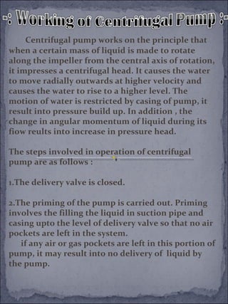
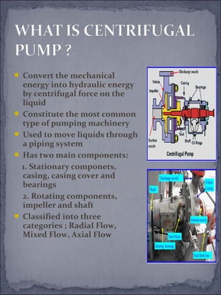
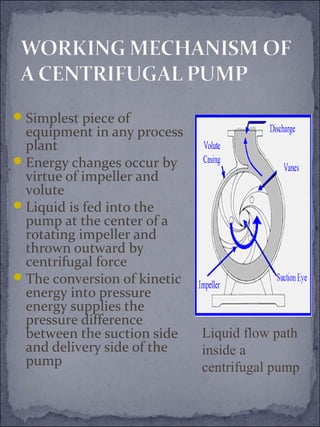
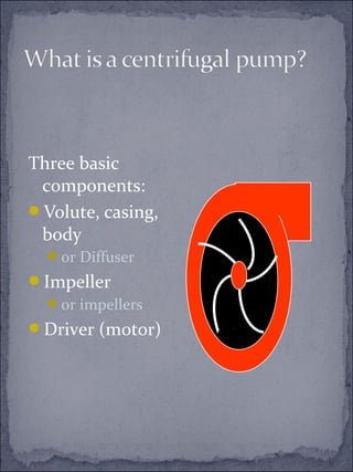
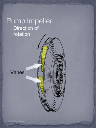
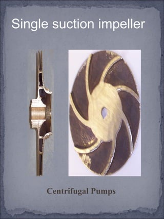
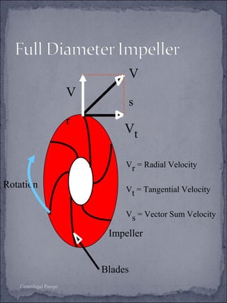
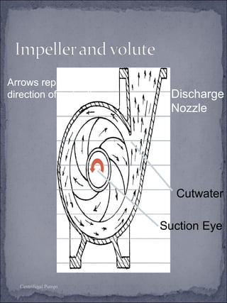
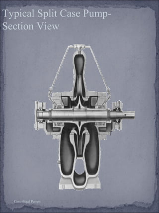
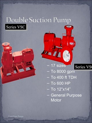
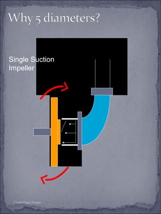
WHAT IS CENTRIFUGAL PUMP? 
WORKING MECHANISM OF A 
CENTRIFUGAL PUMP 
ADVANTEGAES AND 
DISADVANTAGES OF 
CENTRIFUGAL PUMPS
Centrifugal pump works on the principle that 
when a certain mass of liquid is made to rotate 
along the impeller from the central axis of rotation, 
it impresses a centrifugal head. It causes the water 
to move radially outwards at higher velocity and 
causes the water to rise to a higher level. The 
motion of water is restricted by casing of pump, it 
result into pressure build up. In addition , the 
change in angular momentum of liquid during its 
fiow reults into increase in pressure head. 
The steps involved in operation of centrifugal 
pump are as follows : 
1.The delivery valve is closed. 
2.The priming of the pump is carried out. Priming 
involves the filling the liquid in suction pipe and 
casing upto the level of delivery valve so that no air 
pockets are left in the system. 
if any air or gas pockets are left in this portion of 
pump, it may result into no delivery of liquid by 
the pump.
3. The pump shaft and impeller is now rotated 
with the help of an external source of power 
like a motor or any other prime mover. 
The rotation of impeller inside a casing full 
of liquid produces a forced vortex which is 
responsible in imparting the centrifugal head 
to the liquid. It creates a vaccum at the eye of 
impeller and causes liquid to rise into suction 
pipe from the sump. 
4. The speed of impeller should be sufficient to 
produce the centrifugal head such that it can 
initiate discharge from delivery pipe. 
5. Now the delivery valve is opened and the 
liquid is lifted and discharge through the 
delivery pipe due to its high pressure. 
Thus the liquid is continously sucked from 
the sump to impeller eye and it is delivered 
from the casing of pump through the delivery 
pipe. 
6. Before stopping the pump, it is necessary to 
close the delivery pipe otherwise the back 
flow of liquid may take place from the high 
head reservoir.
:- The operation of filling the casing , 
impeller and suction pipe and the 
portion of delivery pump upto delivery 
valve is called priming. 
:- In case the priming of pump is not 
done and the pump is not done and the 
pump is not under the operation, the water 
present in the pump and suction pipe will 
flow back to the sump. The space occupied 
by water will be filled by air.
:- If the pump is now started, the air 
pockets inside the impeller may give 
rise to vortices and cause the 
discontinuity of flow. Under these 
condition, the flow of fluid does not 
commence and the pump runs dry. It 
causes the rubbing and seizing of the 
wearing rings, increases noise level and 
vibrations and finally may cause the 
serious damage to pump. 
:- The priming in resiprocating 
pumps is not required since the 
pumping is done by positively moving 
the fluid out of the cylinder by the 
piston. Hence, the air will be displaced 
from the casing when the pump starts 
and it will get a suction pressure which 
will draw the fluid from the sump.
Priming for small pumps is done 
by hand 
:- A foot valve is essential at the 
bottom of suction pipe 
:- A funnel or priming cup is 
provided to fill the water by hand. 
An air vent is provided in the 
casing of pump. When the water 
is filled, the air escapes through 
the air vent. It is closed once the 
priming is completed
 Convert the mechanical 
energy into hydraulic energy 
by centrifugal force on the 
liquid 
 Constitute the most common 
type of pumping machinery 
 Used to move liquids through 
a piping system 
 Has two main components: 
1. Stationary componets, 
casing, casing cover and 
bearings 
2. Rotating components, 
impeller and shaft 
 Classified into three 
categories ; Radial Flow, 
Mixed Flow, Axial Flow
Simplest piece of 
equipment in any process 
plant 
Energy changes occur by 
virtue of impeller and 
volute 
Liquid is fed into the 
pump at the center of a 
rotating impeller and 
thrown outward by 
centrifugal force 
The conversion of kinetic 
energy into pressure 
energy supplies the 
pressure difference 
between the suction side 
and delivery side of the 
pump 
Liquid flow path 
inside a 
centrifugal pump
Advantages 
Simple in construction and cheap 
Handle liquid with large amounts of 
solids 
No metal to metal fits 
No valves involved in pump operation 
Maintenance costs are lower
Disadvantages 
Cannot handle highly viscous fluids efficiently 
Cannot be operated at high heads 
Maximum efficiency holds over a narrow range 
of conditions
•The power supplied to the pump: 
Where m=mass flow rate, kg/s 
DH= total discharge head, 
N.m/kg 
h=efficiency 
…………(1)
•The power delivered to the fluid: 
…………(2) 
•From equations (1) and (2) efficiency:
n = n × Q 
q 3 4 H 
nq is the specific speed for a unit machine that 
is geometric similar to a machine with the head 
Hq = 1 m and flow rate Q = 1 m3/s 
s q n = 51,55×n
Three basic 
components: 
Volute, casing, 
body 
or Diffuser 
Impeller 
or impellers 
Driver (motor)
Direction of 
rotation 
Vanes 
Centrifugal Pumps
Single suction impeller 
Centrifugal Pumps
• Open 
• Semi-open 
• Closed 
- Single suction 
- Double suction 
• Non-clogging 
• Axial flow 
• Mixed flow 
Centrifugal Pumps
Maximum efficiency lies in the 
range: 
2000<NS<3000 
High head, low capacity pumps: 
500<NS<1000 
Low head, large capacity pumps: 
NS>15000
Rotation 
Centrifugal Pumps 
Vt 
Impeller 
Blades 
V 
r 
V 
s 
Vr = Radial Velocity 
Vt = Tangential Velocity 
Vs = Vector Sum Velocity
Arrows represent the 
direction of water flow Discharge 
Centrifugal Pumps 
Nozzle 
Cutwater 
Suction Eye
SSeerriieess 11551100 
Centrifugal Pumps 
• 26 sizes 
– To 4400 gpm 
– To 520 ft TDH 
– To 150 HP To 
8”x10” 
– General 
Purpose 
Motor
Bell & Gossett 
Series HSC 
Bell & Gossett 
Series HSC 
Centrifugal Pumps 
– 37 sizes 
– To 12500 gpm 
– To 840 ft TDH 
– To 1000 HP 
– To 14”x18” 
– General 
Purpose Motor
Typical Split Case Pump- 
Section View 
Centrifugal Pumps
Centrifugal Pumps 
SSeerriieess VVSSCCSS 
SSeerriieess VVSSCC 
– 17 sizes 
– To 8000 gpm 
– To 400 ft TDH 
– To 600 HP 
– To 12”x14” 
– General Purpose 
Motor
Standard construction, any impeller 
Mechanical seal 
Internally flushed, seal 
cavity 
Variety of seal materials 
Stuffing box construction, any impeller 
External flush lines 
Compression packing rings 
Single flushed mechanical 
seal 
Centrifugal Pumps
Standard construction, any 
impeller 
Mechanical seal 
Internally flushed, seal cavity 
Variety of seal materials 
Centrifugal Pumps
Temperature of the flushing 
water. 
225ºF to 250ºF 
System pH. 
7 to 9 for ceramic seals 
up to 11 for tungsten carbide seals 
Concentration of dissolved solids. 
TDS less than 1000 ppm 
Concentration of suspended 
solids. 
Less than 20 ppm 
Silica, less than 10 ppm 
Centrifugal Pumps
Stuffing box construction, any 
impeller 
External flush lines 
Internal or External Fluid 
Compression packing rings 
Single flushed mechanical seal 
Centrifugal Pumps
Impeller 
Single suction or double 
suction. 
Volutes 
Base mounted or in-line. 
Internally flushed or stuffing 
box. 
Single stage or multi stage. 
Packing, seal or wet rotor. 
Centrifugal Pumps
5 dia. 
RIGHT WRONG 
1. Pipe supported 
2. Length of 
suction piping 
allows even 
impeller 
loading 
Centrifugal Pumps 
1. Pipe weight 
hangs on 
pump flange. 
2. Short suction 
pipe results in 
uneven 
impeller 
loading.
Single Suction 
Impeller 
Centrifugal Pumps
The amount of fluid 
The properties of the fluid 
Type of power supply 
Cost and mechanical efficiency of the pump
Centrifugalpump

Centrifugalpump

  • 3.
    WHAT IS CENTRIFUGALPUMP? WORKING MECHANISM OF A CENTRIFUGAL PUMP ADVANTEGAES AND DISADVANTAGES OF CENTRIFUGAL PUMPS
  • 4.
    Centrifugal pump workson the principle that when a certain mass of liquid is made to rotate along the impeller from the central axis of rotation, it impresses a centrifugal head. It causes the water to move radially outwards at higher velocity and causes the water to rise to a higher level. The motion of water is restricted by casing of pump, it result into pressure build up. In addition , the change in angular momentum of liquid during its fiow reults into increase in pressure head. The steps involved in operation of centrifugal pump are as follows : 1.The delivery valve is closed. 2.The priming of the pump is carried out. Priming involves the filling the liquid in suction pipe and casing upto the level of delivery valve so that no air pockets are left in the system. if any air or gas pockets are left in this portion of pump, it may result into no delivery of liquid by the pump.
  • 5.
    3. The pumpshaft and impeller is now rotated with the help of an external source of power like a motor or any other prime mover. The rotation of impeller inside a casing full of liquid produces a forced vortex which is responsible in imparting the centrifugal head to the liquid. It creates a vaccum at the eye of impeller and causes liquid to rise into suction pipe from the sump. 4. The speed of impeller should be sufficient to produce the centrifugal head such that it can initiate discharge from delivery pipe. 5. Now the delivery valve is opened and the liquid is lifted and discharge through the delivery pipe due to its high pressure. Thus the liquid is continously sucked from the sump to impeller eye and it is delivered from the casing of pump through the delivery pipe. 6. Before stopping the pump, it is necessary to close the delivery pipe otherwise the back flow of liquid may take place from the high head reservoir.
  • 6.
    :- The operationof filling the casing , impeller and suction pipe and the portion of delivery pump upto delivery valve is called priming. :- In case the priming of pump is not done and the pump is not done and the pump is not under the operation, the water present in the pump and suction pipe will flow back to the sump. The space occupied by water will be filled by air.
  • 7.
    :- If thepump is now started, the air pockets inside the impeller may give rise to vortices and cause the discontinuity of flow. Under these condition, the flow of fluid does not commence and the pump runs dry. It causes the rubbing and seizing of the wearing rings, increases noise level and vibrations and finally may cause the serious damage to pump. :- The priming in resiprocating pumps is not required since the pumping is done by positively moving the fluid out of the cylinder by the piston. Hence, the air will be displaced from the casing when the pump starts and it will get a suction pressure which will draw the fluid from the sump.
  • 8.
    Priming for smallpumps is done by hand :- A foot valve is essential at the bottom of suction pipe :- A funnel or priming cup is provided to fill the water by hand. An air vent is provided in the casing of pump. When the water is filled, the air escapes through the air vent. It is closed once the priming is completed
  • 9.
     Convert themechanical energy into hydraulic energy by centrifugal force on the liquid  Constitute the most common type of pumping machinery  Used to move liquids through a piping system  Has two main components: 1. Stationary componets, casing, casing cover and bearings 2. Rotating components, impeller and shaft  Classified into three categories ; Radial Flow, Mixed Flow, Axial Flow
  • 10.
    Simplest piece of equipment in any process plant Energy changes occur by virtue of impeller and volute Liquid is fed into the pump at the center of a rotating impeller and thrown outward by centrifugal force The conversion of kinetic energy into pressure energy supplies the pressure difference between the suction side and delivery side of the pump Liquid flow path inside a centrifugal pump
  • 11.
    Advantages Simple inconstruction and cheap Handle liquid with large amounts of solids No metal to metal fits No valves involved in pump operation Maintenance costs are lower
  • 12.
    Disadvantages Cannot handlehighly viscous fluids efficiently Cannot be operated at high heads Maximum efficiency holds over a narrow range of conditions
  • 13.
    •The power suppliedto the pump: Where m=mass flow rate, kg/s DH= total discharge head, N.m/kg h=efficiency …………(1)
  • 14.
    •The power deliveredto the fluid: …………(2) •From equations (1) and (2) efficiency:
  • 15.
    n = n× Q q 3 4 H nq is the specific speed for a unit machine that is geometric similar to a machine with the head Hq = 1 m and flow rate Q = 1 m3/s s q n = 51,55×n
  • 16.
    Three basic components: Volute, casing, body or Diffuser Impeller or impellers Driver (motor)
  • 17.
    Direction of rotation Vanes Centrifugal Pumps
  • 18.
    Single suction impeller Centrifugal Pumps
  • 19.
    • Open •Semi-open • Closed - Single suction - Double suction • Non-clogging • Axial flow • Mixed flow Centrifugal Pumps
  • 20.
    Maximum efficiency liesin the range: 2000<NS<3000 High head, low capacity pumps: 500<NS<1000 Low head, large capacity pumps: NS>15000
  • 21.
    Rotation Centrifugal Pumps Vt Impeller Blades V r V s Vr = Radial Velocity Vt = Tangential Velocity Vs = Vector Sum Velocity
  • 22.
    Arrows represent the direction of water flow Discharge Centrifugal Pumps Nozzle Cutwater Suction Eye
  • 23.
    SSeerriieess 11551100 CentrifugalPumps • 26 sizes – To 4400 gpm – To 520 ft TDH – To 150 HP To 8”x10” – General Purpose Motor
  • 24.
    Bell & Gossett Series HSC Bell & Gossett Series HSC Centrifugal Pumps – 37 sizes – To 12500 gpm – To 840 ft TDH – To 1000 HP – To 14”x18” – General Purpose Motor
  • 25.
    Typical Split CasePump- Section View Centrifugal Pumps
  • 26.
    Centrifugal Pumps SSeerriieessVVSSCCSS SSeerriieess VVSSCC – 17 sizes – To 8000 gpm – To 400 ft TDH – To 600 HP – To 12”x14” – General Purpose Motor
  • 27.
    Standard construction, anyimpeller Mechanical seal Internally flushed, seal cavity Variety of seal materials Stuffing box construction, any impeller External flush lines Compression packing rings Single flushed mechanical seal Centrifugal Pumps
  • 28.
    Standard construction, any impeller Mechanical seal Internally flushed, seal cavity Variety of seal materials Centrifugal Pumps
  • 29.
    Temperature of theflushing water. 225ºF to 250ºF System pH. 7 to 9 for ceramic seals up to 11 for tungsten carbide seals Concentration of dissolved solids. TDS less than 1000 ppm Concentration of suspended solids. Less than 20 ppm Silica, less than 10 ppm Centrifugal Pumps
  • 30.
    Stuffing box construction,any impeller External flush lines Internal or External Fluid Compression packing rings Single flushed mechanical seal Centrifugal Pumps
  • 31.
    Impeller Single suctionor double suction. Volutes Base mounted or in-line. Internally flushed or stuffing box. Single stage or multi stage. Packing, seal or wet rotor. Centrifugal Pumps
  • 32.
    5 dia. RIGHTWRONG 1. Pipe supported 2. Length of suction piping allows even impeller loading Centrifugal Pumps 1. Pipe weight hangs on pump flange. 2. Short suction pipe results in uneven impeller loading.
  • 33.
    Single Suction Impeller Centrifugal Pumps
  • 34.
    The amount offluid The properties of the fluid Type of power supply Cost and mechanical efficiency of the pump

Editor's Notes