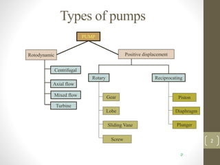
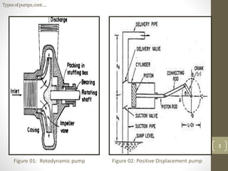
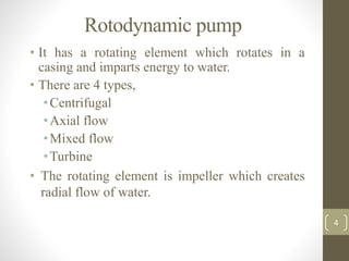
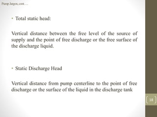
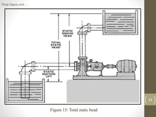
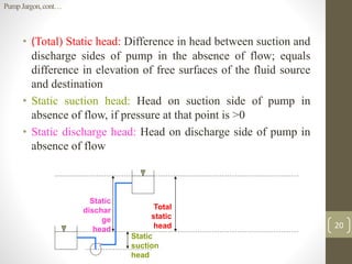
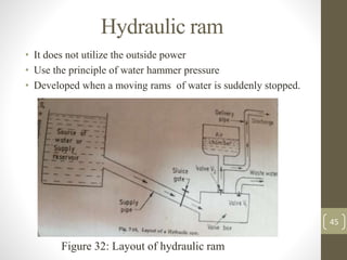
The document discusses various types of water pumps, highlighting the differences between rotodynamic and positive displacement pumps, as well as their mechanisms and operational principles. It covers the classification of pumps, components like impellers and casings, advantages and disadvantages of different types, and specialized pumps such as diaphragm and hydraulic rams. Additionally, it explains key terms related to pump operation, including static head and dynamic head.
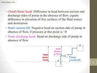
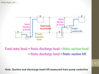
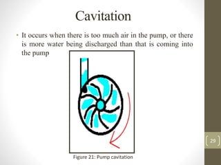
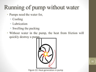


![Pipe materials and types of joints [autosaved]](https://cdn.slidesharecdn.com/ss_thumbnails/pipematerialsandtypesofjointsautosaved-180719140405-thumbnail.jpg?width=640&height=640&fit=bounds)


