1) A circuit breaker protects an electrical circuit from damage caused by overloading or short circuit by interrupting current flow.
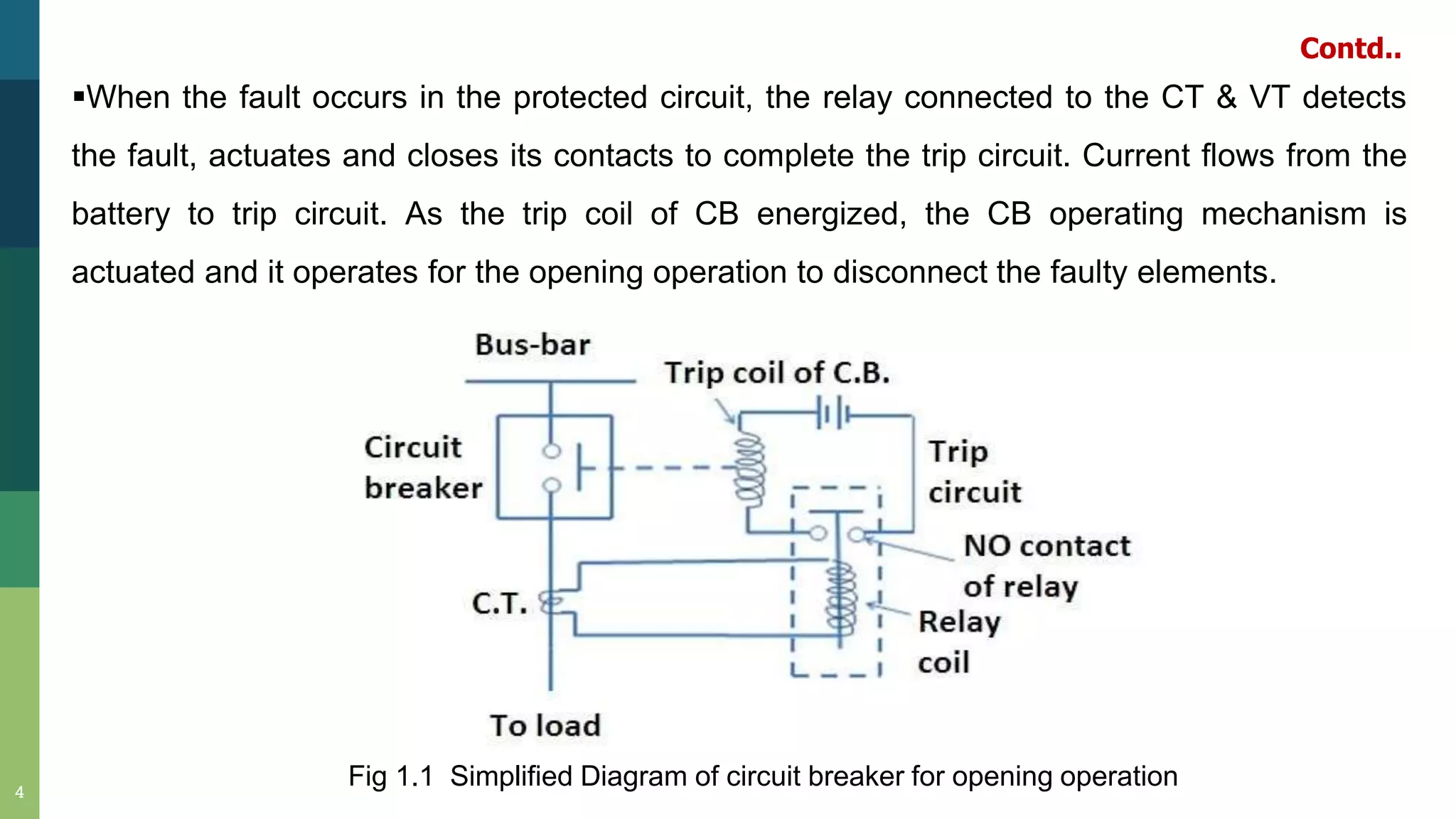
2) When a fault occurs, a relay detects it and energizes the circuit breaker's trip coil, actuating the operating mechanism to open the contacts and disconnect faulty elements.
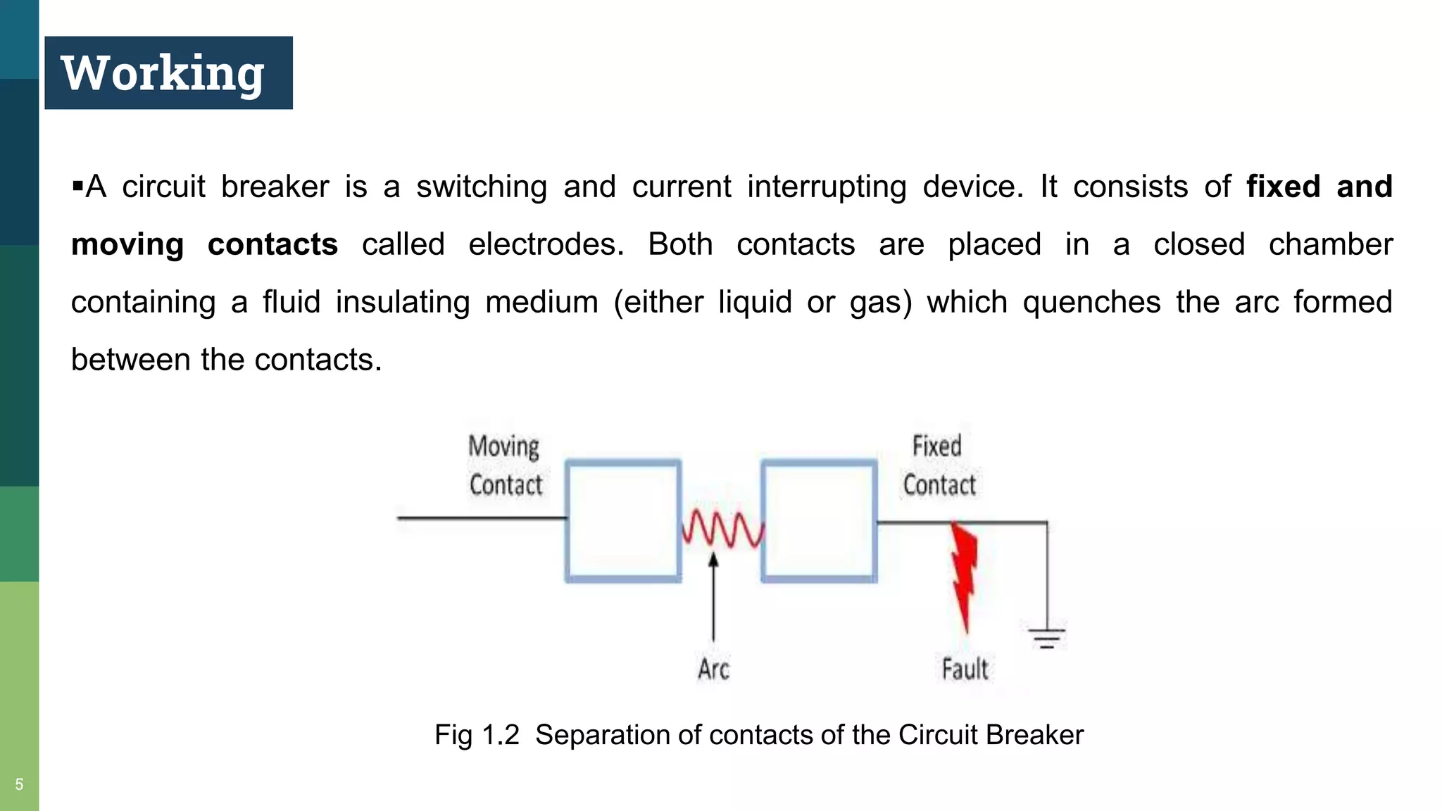
3) When contacts open under fault conditions, an arc is struck that must be extinguished quickly to prevent damage. Circuit breakers use various methods like increasing arc length, cooling it, or taking advantage of current zeros in AC to extinguish the arc.