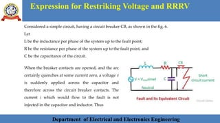
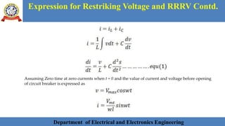
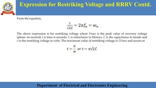
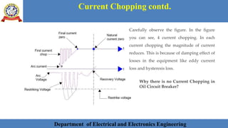
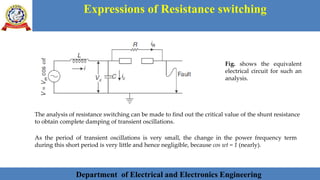
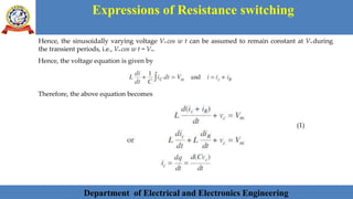
SlideShare a Scribd company logo
1 of 46
LENDI INSTITUTE OF ENGINEERING AND TECHNOLOGY
Jonnada, Andhra Pradesh- 535005
UNIT -I
CIRCUIT BREAKERS (PART I)
Presented by,
Dr. Rohit Babu, Associate Professor
Department of Electrical and Electronics Engineering
SYLLABUS
Department of Electrical and Electronics Engineering
Miniature Circuit Breaker (MCB)– Elementary principles of arc interruption–
Restriking Voltage and Recovery voltages– Restriking phenomenon - RRRV–
Average and Max. RRRV– Current chopping and Resistance switching–
Introduction to oil circuit breakers– Description and operation of Air Blast–
Vacuum and SF6 circuit breakers– CB ratings and specifications– Concept of
Auto reclosing.
Department of Electrical and Electronics Engineering 3
MINIATURE CIRCUIT BREAKER (MCB)
Department of Electrical and Electronics Engineering
A Miniature Circuit Breaker (MCB) is an
automatically operated electrical switch
used to protect low voltage electrical
circuits from damage caused by excess
current from an overload or short circuit.
MCBs are typically rated up to a current
up to 125 A, do not have adjustable trip
characteristics, and can be thermal or
thermal-magnetic in operation.
Fig. 1 MCB
Department of Electrical and Electronics Engineering 4Department of Electrical and Electronics Engineering 4
MCB: Working Principle
Department of Electrical and Electronics Engineering
Fig. 2. MCB working
framework
Department of Electrical and Electronics EngineeringDepartment of Electrical and Electronics Engineering 5Department of Electrical and Electronics Engineering 5
ELEMENTARY PRINCIPLES OF ARC
INTERRUPTION
Department of Electrical and Electronics Engineering
Arc Interruption Theory
The insulating material (may be fluid or air) used in circuit breaker should serve two
important functions.
They are written as follows:
1. It should provide sufficient insulation between the contacts when circuit breaker
opens.
2. It should extinguish the arc occurring between the contacts when circuit breaker
opens.
Department of Electrical and Electronics EngineeringDepartment of Electrical and Electronics Engineering 6Department of Electrical and Electronics Engineering 6
ELEMENTARY PRINCIPLES OF ARC INTERRUPTION:
METHODS OF ARC INTERRUPTION
Department of Electrical and Electronics Engineering
There are two methods by which interruption is done.
1. High resistance method
• In this method, its resistance is increased so as to reduce the current to a value
insufficient to maintain the arc.
• The arc resistance can be increased by cooling, lengthening, constraining and splitting
the arc.
• When current is interrupted the energy associated with its magnetic field appears in
the form of electrostatic energy.
• A high voltage appears across the contacts of the circuit breaker.
• If this voltage is very high and more than the withstanding capacity of the gap between
the contacts, the arc will strike again.
Department of Electrical and Electronics Engineering 7Department of Electrical and Electronics EngineeringDepartment of Electrical and Electronics Engineering 7Department of Electrical and Electronics Engineering 7
ELEMENTARY PRINCIPLES OF ARC INTERRUPTION:
METHODS OF ARC INTERRUPTION Contd.
Department of Electrical and Electronics Engineering
• This method is applicable only in case of ac circuit breakers.
• In case of ac supply, the current wave passes through a zero point, 100 times per second
at the supply frequency of 50 Hz. This feature of ac is utilized for arc interruption.
• The current is not interrupted at any point other than the zero current instant,
otherwise a high transient voltage will occur across the contact gap.
• The current is not allowed to rise again after a zero current occurs.
• There are two theories to explain the zero current interruption of the arc.
(i) Recovery rate theory (Slepain’s Theory)
(ii) Energy balance theory (Cassie’s Theory)
2. Current Zero Interruption
Department of Electrical and Electronics Engineering 8Department of Electrical and Electronics Engineering 8Department of Electrical and Electronics EngineeringDepartment of Electrical and Electronics Engineering 8Department of Electrical and Electronics Engineering 8
ELEMENTARY PRINCIPLES OF ARC INTERRUPTION:
METHODS OF ARC INTERRUPTION Contd.
Department of Electrical and Electronics Engineering
• Restriking Voltage
• Recovery Voltage
• Active Recovery Voltage
• Arc Voltage
Before going in details about these theories, we should know the following terms.
Department of Electrical and Electronics Engineering 9Department of Electrical and Electronics Engineering 9Department of Electrical and Electronics Engineering 9Department of Electrical and Electronics EngineeringDepartment of Electrical and Electronics Engineering 9Department of Electrical and Electronics Engineering 9
ELEMENTARY PRINCIPLES OF ARC INTERRUPTION:
METHODS OF ARC INTERRUPTION Contd.
Department of Electrical and Electronics Engineering
(i) Recovery rate theory (Slepain’s Theory)
• The arc is a column of ionised gases.
• To extinguish the arc, the electrons and ions are to be removed from the gap immediately
after the current reaches a natural zero.
• Ions and electrons can be removed either by recombining them into neutral molecules or by
sweeping them away by inserting insulating medium (gas or liquid) into the gap.
• The arc is interrupted if ions are removed from the gap at a rate faster than the rate of
ionisation.
• In this method, the rate at which the gap recovers its dielectric strength is compared with
the rate at which the gap recovers its dielectric strength is compared with the rate at which
the restriking voltage (transient voltage) across the gap rises.
Department of Electrical and Electronics Engineering 10
• If the dielectric strength increases more rapidly than the restriking voltage, the arc is
extinguished.
• If the restriking voltage rises more rapidly than the dielectric strength, the ionisation persists and
breakdown of the gap occurs, resulting in an arc for another half cycle.
• Fig. 3 (a & b) explains the principle of recovery rate theory.
Department of Electrical and Electronics Engineering 10Department of Electrical and Electronics Engineering 10Department of Electrical and Electronics Engineering 10Department of Electrical and Electronics EngineeringDepartment of Electrical and Electronics Engineering 10Department of Electrical and Electronics Engineering 10
ELEMENTARY PRINCIPLES OF ARC INTERRUPTION:
METHODS OF ARC INTERRUPTION Contd.
Department of Electrical and Electronics Engineering
Department of Electrical and Electronics Engineering 11Department of Electrical and Electronics Engineering 11Department of Electrical and Electronics Engineering 11Department of Electrical and Electronics Engineering 11Department of Electrical and Electronics Engineering 11Department of Electrical and Electronics EngineeringDepartment of Electrical and Electronics Engineering 11Department of Electrical and Electronics Engineering 11
ELEMENTARY PRINCIPLES OF ARC INTERRUPTION:
METHODS OF ARC INTERRUPTION Contd.
Department of Electrical and Electronics Engineering
(ii) Energy balance theory (Cassie’s Theory)
• The space between the contacts contains some ionised gas immediately after current zero and
hence, it has a finite post-zero resistance.
• At the current zero moment, power is zero because restricking voltage is zero.
• When the arc is finally extinguished, the power again becomes zero, the gap is fully de-ionised
and its resistance is infinitely high.
• In between these two limits, first the power increases, reaches a maximum value, then decreases
and finally reaches zero value as shown in Fig. 14.6.
• Due to the rise of restriking voltage and associated current, energy is generated in the space
between the contacts.
• The energy appears in the form of heat.
Department of Electrical and Electronics Engineering 12Department of Electrical and Electronics Engineering 12Department of Electrical and Electronics Engineering 12Department of Electrical and Electronics Engineering 12Department of Electrical and Electronics Engineering 12Department of Electrical and Electronics Engineering 12Department of Electrical and Electronics EngineeringDepartment of Electrical and Electronics Engineering 12Department of Electrical and Electronics Engineering 12
ELEMENTARY PRINCIPLES OF ARC INTERRUPTION:
METHODS OF ARC INTERRUPTION Contd.
Department of Electrical and Electronics Engineering
• The circuit breaker is designed to remove this
generated heat as early as possible by cooling
the gap, giving a blast of air or flow of oil at
high velocity and pressure.
• If the rate of removal of heat is faster than the
rate of heat generation the arc is extinguished.
• If the rate of heat generation is more than the
rate of heat dissipation, the space breaks down
again resulting in an arc for another half cycle,
as shown in Fig. 4
Department of Electrical and Electronics EngineeringDepartment of Electrical and Electronics Engineering 13Department of Electrical and Electronics Engineering 13Department of Electrical and Electronics Engineering 13Department of Electrical and Electronics Engineering 13Department of Electrical and Electronics Engineering 13Department of Electrical and Electronics Engineering 13Department of Electrical and Electronics EngineeringDepartment of Electrical and Electronics Engineering 13Department of Electrical and Electronics Engineering 13
RESTRIKING VOLTAGE AND RECOVERY
VOLTAGE
Department of Electrical and Electronics Engineering
• The transient voltage which appears
across the breaker contacts at the instant
of arc being extinguished is known as
restriking voltage.
• The power frequency rms voltage, which
appears across the breaker contacts after
the arc is finally extinguished and
transient oscillations die out is called
recovery voltage.
• Fig. 5 shows the restriking and recovery
voltage.
Department of Electrical and Electronics Engineering 14Department of Electrical and Electronics EngineeringDepartment of Electrical and Electronics Engineering 14Department of Electrical and Electronics Engineering 14Department of Electrical and Electronics Engineering 14Department of Electrical and Electronics Engineering 14Department of Electrical and Electronics Engineering 14Department of Electrical and Electronics Engineering 14Department of Electrical and Electronics EngineeringDepartment of Electrical and Electronics Engineering 14Department of Electrical and Electronics Engineering 14
Arc formation: Video 1
Department of Electrical and Electronics Engineering
Department of Electrical and Electronics Engineering 15Department of Electrical and Electronics Engineering 15Department of Electrical and Electronics EngineeringDepartment of Electrical and Electronics Engineering 15Department of Electrical and Electronics Engineering 15Department of Electrical and Electronics Engineering 15Department of Electrical and Electronics Engineering 15Department of Electrical and Electronics Engineering 15Department of Electrical and Electronics Engineering 15Department of Electrical and Electronics EngineeringDepartment of Electrical and Electronics Engineering 15Department of Electrical and Electronics Engineering 15
Expression for Restriking Voltage and RRRV
Department of Electrical and Electronics Engineering
Considered a simple circuit, having a circuit breaker CB, as shown in the fig. 6.
Let
L be the inductance per phase of the system up to the fault point;
R be the resistance per phase of the system up to the fault point, and
C be the capacitance of the circuit.
When the breaker contacts are opened, and the arc
certainly quenches at some current zero, a voltage v
is suddenly applied across the capacitor and
therefore across the circuit breaker contacts. The
current i which would flow to the fault is not
injected in the capacitor and inductor. Thus
Department of Electrical and Electronics Engineering 16Department of Electrical and Electronics Engineering 16Department of Electrical and Electronics Engineering 16Department of Electrical and Electronics EngineeringDepartment of Electrical and Electronics Engineering 16Department of Electrical and Electronics Engineering 16Department of Electrical and Electronics Engineering 16Department of Electrical and Electronics Engineering 16Department of Electrical and Electronics Engineering 16Department of Electrical and Electronics Engineering 16Department of Electrical and Electronics EngineeringDepartment of Electrical and Electronics Engineering 16Department of Electrical and Electronics Engineering 16
Expression for Restriking Voltage and RRRV Contd.
Department of Electrical and Electronics Engineering
Assuming Zero time at zero currents when t = 0 and the value of current and voltage before opening
of circuit breaker is expressed as
Department of Electrical and Electronics Engineering 17Department of Electrical and Electronics Engineering 17Department of Electrical and Electronics Engineering 17Department of Electrical and Electronics Engineering 17Department of Electrical and Electronics EngineeringDepartment of Electrical and Electronics Engineering 17Department of Electrical and Electronics Engineering 17Department of Electrical and Electronics Engineering 17Department of Electrical and Electronics Engineering 17Department of Electrical and Electronics Engineering 17Department of Electrical and Electronics Engineering 17Department of Electrical and Electronics EngineeringDepartment of Electrical and Electronics Engineering 17Department of Electrical and Electronics Engineering 17
Expression for Restriking Voltage and RRRV Contd.
Department of Electrical and Electronics Engineering
On substituting the above values in equation (1), we get
The solution of the standard equation is
Department of Electrical and Electronics Engineering 18Department of Electrical and Electronics Engineering 18Department of Electrical and Electronics Engineering 18Department of Electrical and Electronics Engineering 18Department of Electrical and Electronics Engineering 18Department of Electrical and Electronics EngineeringDepartment of Electrical and Electronics Engineering 18Department of Electrical and Electronics Engineering 18Department of Electrical and Electronics Engineering 18Department of Electrical and Electronics Engineering 18Department of Electrical and Electronics Engineering 18Department of Electrical and Electronics Engineering 18Department of Electrical and Electronics EngineeringDepartment of Electrical and Electronics Engineering 18Department of Electrical and Electronics Engineering 18
Expression for Restriking Voltage and RRRV Contd.
Department of Electrical and Electronics Engineering
From the equation,
The above expression is for restriking voltage where Vmax is the peak value of recovery voltage
(phase -to-neutral) t is time is seconds. L is inductance in Henrys, C is the capacitance in farads and
v is the restriking voltage in volts. The maximum value of restriking voltage is 2Vmax and occurs at
Department of Electrical and Electronics Engineering 19Department of Electrical and Electronics Engineering 19Department of Electrical and Electronics Engineering 19Department of Electrical and Electronics Engineering 19Department of Electrical and Electronics Engineering 19Department of Electrical and Electronics Engineering 19Department of Electrical and Electronics EngineeringDepartment of Electrical and Electronics Engineering 19Department of Electrical and Electronics Engineering 19Department of Electrical and Electronics Engineering 19Department of Electrical and Electronics Engineering 19Department of Electrical and Electronics Engineering 19Department of Electrical and Electronics Engineering 19Department of Electrical and Electronics EngineeringDepartment of Electrical and Electronics Engineering 19Department of Electrical and Electronics Engineering 19
Expression for Restriking Voltage and RRRV:
Characteristic of Restriking Voltage
Department of Electrical and Electronics Engineering
The important characteristic of restriking voltage which affects the performance of the circuit
breaker is as follows –
Amplitude Factor – It is defined as the ratio of the peak of transient voltage to the peak system
frequency voltage.
The rate of Rising of Restriking Voltage – It is defined as the slope of the steepness tangent of the
restriking voltage curve. It is expressed in kV/µs. RRRV is directly proportional to the natural
frequency. The expression for the restriking voltage is expressed as
Department of Electrical and Electronics Engineering 20Department of Electrical and Electronics Engineering 20Department of Electrical and Electronics Engineering 20Department of Electrical and Electronics Engineering 20Department of Electrical and Electronics Engineering 20Department of Electrical and Electronics Engineering 20Department of Electrical and Electronics Engineering 20Department of Electrical and Electronics EngineeringDepartment of Electrical and Electronics Engineering 20Department of Electrical and Electronics Engineering 20Department of Electrical and Electronics Engineering 20Department of Electrical and Electronics Engineering 20Department of Electrical and Electronics Engineering 20Department of Electrical and Electronics Engineering 20Department of Electrical and Electronics EngineeringDepartment of Electrical and Electronics Engineering 20Department of Electrical and Electronics Engineering 20
Current Chopping
Department of Electrical and Electronics Engineering
What is Current Chopping?
• Current Chopping in circuit breaker is defined as a phenomena in which current is forcibly
interrupted before the natural current zero.
• Current Chopping is mainly observed in Vacuum Circuit Breaker and Air Blast Circuit Breaker.
• There is no such phenomena in Oil Circuit Breaker.
• Current chopping is predominant while switching Shunt Reactor or unloaded Transformer.
Department of Electrical and Electronics Engineering 21Department of Electrical and Electronics Engineering 21Department of Electrical and Electronics Engineering 21Department of Electrical and Electronics Engineering 21Department of Electrical and Electronics Engineering 21Department of Electrical and Electronics Engineering 21Department of Electrical and Electronics Engineering 21Department of Electrical and Electronics Engineering 21Department of Electrical and Electronics EngineeringDepartment of Electrical and Electronics Engineering 21Department of Electrical and Electronics Engineering 21Department of Electrical and Electronics Engineering 21Department of Electrical and Electronics Engineering 21Department of Electrical and Electronics Engineering 21Department of Electrical and Electronics Engineering 21Department of Electrical and Electronics EngineeringDepartment of Electrical and Electronics Engineering 21Department of Electrical and Electronics Engineering 21
Current Chopping contd.
Department of Electrical and Electronics Engineering
Theory of Current Chopping
• Generally the arc extinction in a circuit breaker take place at natural current zero.
• But this is true if the capacity of the breaker to extinguish the arc is varies with the level of fault
current.
Consider a shunt reactor as
shown in figure.
Department of Electrical and Electronics Engineering 22Department of Electrical and Electronics Engineering 22Department of Electrical and Electronics Engineering 22Department of Electrical and Electronics Engineering 22Department of Electrical and Electronics Engineering 22Department of Electrical and Electronics Engineering 22Department of Electrical and Electronics Engineering 22Department of Electrical and Electronics Engineering 22Department of Electrical and Electronics Engineering 22Department of Electrical and Electronics EngineeringDepartment of Electrical and Electronics Engineering 22Department of Electrical and Electronics Engineering 22Department of Electrical and Electronics Engineering 22Department of Electrical and Electronics Engineering 22Department of Electrical and Electronics Engineering 22Department of Electrical and Electronics Engineering 22Department of Electrical and Electronics EngineeringDepartment of Electrical and Electronics Engineering 22Department of Electrical and Electronics Engineering 22
Current Chopping contd.
Department of Electrical and Electronics Engineering
The stored energy in the inductance of reactor is basically transferred to the capacitor. Therefore
mathematically we can write as
LI2 / 2 = CV2 / 2
Here V = Voltage across the capacitor
Thus, V = I √(L/C)
This is the prospective voltage across the capacitor during current chopping.
Let us consider a simple example to have an idea of magnitude of prospective voltage. Let the value
of L = 64 mH and C = 0.001 uF then the induced voltage for a chopping current of 10 A will be
V = 10x√(64×10-3 / 0.001×10⁻⁶ )= 80 kV
Department of Electrical and Electronics Engineering 23Department of Electrical and Electronics Engineering 23Department of Electrical and Electronics Engineering 23Department of Electrical and Electronics Engineering 23Department of Electrical and Electronics Engineering 23Department of Electrical and Electronics Engineering 23Department of Electrical and Electronics Engineering 23Department of Electrical and Electronics Engineering 23Department of Electrical and Electronics Engineering 23Department of Electrical and Electronics Engineering 23Department of Electrical and Electronics EngineeringDepartment of Electrical and Electronics Engineering 23Department of Electrical and Electronics Engineering 23Department of Electrical and Electronics Engineering 23Department of Electrical and Electronics Engineering 23Department of Electrical and Electronics Engineering 23Department of Electrical and Electronics Engineering 23Department of Electrical and Electronics EngineeringDepartment of Electrical and Electronics Engineering 23Department of Electrical and Electronics Engineering 23
Current Chopping contd.
Department of Electrical and Electronics Engineering
Carefully observe the figure. In the figure
you can see, 4 current chopping. In each
current chopping the magnitude of current
reduces. This is because of damping effect of
losses in the equipment like eddy current
loss and hysteresis loss.
Why there is no Current Chopping in
Oil Circuit Breaker?
Department of Electrical and Electronics Engineering 24Department of Electrical and Electronics Engineering 24Department of Electrical and Electronics Engineering 24Department of Electrical and Electronics Engineering 24Department of Electrical and Electronics Engineering 24Department of Electrical and Electronics Engineering 24Department of Electrical and Electronics Engineering 24Department of Electrical and Electronics Engineering 24Department of Electrical and Electronics Engineering 24Department of Electrical and Electronics Engineering 24Department of Electrical and Electronics Engineering 24Department of Electrical and Electronics EngineeringDepartment of Electrical and Electronics Engineering 24Department of Electrical and Electronics Engineering 24Department of Electrical and Electronics Engineering 24Department of Electrical and Electronics Engineering 24Department of Electrical and Electronics Engineering 24Department of Electrical and Electronics Engineering 24Department of Electrical and Electronics EngineeringDepartment of Electrical and Electronics Engineering 24Department of Electrical and Electronics Engineering 24
Resistance switching
Department of Electrical and Electronics Engineering
A fixed connection of resistance in parallel with the
contact space or arc is called the resistance switching.
Severe voltage occurs in the system because of
two reasons, firstly because of the breaking of
low voltage current, and secondly because of the
breaking of capacitive current.
The severe voltage may endanger the operation
of the system.
It can be avoided by using resistance switching
(by connecting the resistor across the contacts of
the circuit breaker).
Department of Electrical and Electronics Engineering 25Department of Electrical and Electronics Engineering 25Department of Electrical and Electronics Engineering 25Department of Electrical and Electronics Engineering 25Department of Electrical and Electronics Engineering 25Department of Electrical and Electronics Engineering 25Department of Electrical and Electronics Engineering 25Department of Electrical and Electronics Engineering 25Department of Electrical and Electronics Engineering 25Department of Electrical and Electronics Engineering 25Department of Electrical and Electronics Engineering 25Department of Electrical and Electronics Engineering 25Department of Electrical and Electronics EngineeringDepartment of Electrical and Electronics Engineering 25Department of Electrical and Electronics Engineering 25Department of Electrical and Electronics Engineering 25Department of Electrical and Electronics Engineering 25Department of Electrical and Electronics Engineering 25Department of Electrical and Electronics Engineering 25Department of Electrical and Electronics EngineeringDepartment of Electrical and Electronics Engineering 25Department of Electrical and Electronics Engineering 25
Resistance switching
Department of Electrical and Electronics Engineering
The shunt resistor also helps in limiting the oscillatory growth of restriking voltage transients.
It can be proved mathematically that the natural frequency (fn) of oscillations of the circuit shown is
given as
To sum up, resistor across the circuit breaker contacts may be used to perform any one or more of
the following functions.
•It reduces the RRRV ( Rate of Rising of Restriking Voltage ) burden on the circuit breaker.
•It reduces the high-frequency restriking voltage transients during switching out inductive or
capacitive loads.
•In a multi-break circuit breaker, it helps in distributing the transient recovery voltage more
uniformly across the contact gaps.
Department of Electrical and Electronics Engineering 26Department of Electrical and Electronics Engineering 26Department of Electrical and Electronics Engineering 26Department of Electrical and Electronics Engineering 26Department of Electrical and Electronics Engineering 26Department of Electrical and Electronics Engineering 26Department of Electrical and Electronics Engineering 26Department of Electrical and Electronics Engineering 26Department of Electrical and Electronics Engineering 26Department of Electrical and Electronics Engineering 26Department of Electrical and Electronics Engineering 26Department of Electrical and Electronics Engineering 26Department of Electrical and Electronics Engineering 26Department of Electrical and Electronics EngineeringDepartment of Electrical and Electronics Engineering 26Department of Electrical and Electronics Engineering 26Department of Electrical and Electronics Engineering 26Department of Electrical and Electronics Engineering 26Department of Electrical and Electronics Engineering 26Department of Electrical and Electronics Engineering 26Department of Electrical and Electronics EngineeringDepartment of Electrical and Electronics Engineering 26Department of Electrical and Electronics Engineering 26
Resistance switching
Department of Electrical and Electronics Engineering
• To reduce the transient recovery voltage requires a considerably lower value of resistor whereas
for voltage equalisation a resistor of relatively high ohmic value will be required.
• In this case it is required that its resistance be low compared with the reactance of the
capacitance, shunting the breaks at the frequency of the recovery transient.
• It is often necessary to compromise and make one resistor do more than one of these jobs Critical
restriking voltage damping is obtained if
Department of Electrical and Electronics Engineering 27Department of Electrical and Electronics Engineering 27Department of Electrical and Electronics Engineering 27Department of Electrical and Electronics Engineering 27Department of Electrical and Electronics Engineering 27Department of Electrical and Electronics Engineering 27Department of Electrical and Electronics Engineering 27Department of Electrical and Electronics Engineering 27Department of Electrical and Electronics Engineering 27Department of Electrical and Electronics Engineering 27Department of Electrical and Electronics Engineering 27Department of Electrical and Electronics Engineering 27Department of Electrical and Electronics Engineering 27Department of Electrical and Electronics Engineering 27Department of Electrical and Electronics EngineeringDepartment of Electrical and Electronics Engineering 27Department of Electrical and Electronics Engineering 27Department of Electrical and Electronics Engineering 27Department of Electrical and Electronics Engineering 27Department of Electrical and Electronics Engineering 27Department of Electrical and Electronics Engineering 27Department of Electrical and Electronics EngineeringDepartment of Electrical and Electronics Engineering 27Department of Electrical and Electronics Engineering 27
Resistance switching
Department of Electrical and Electronics Engineering
• To reduce the transient recovery voltage requires a considerably lower value of resistor whereas
for voltage equalisation a resistor of relatively high ohmic value will be required.
• In this case it is required that its resistance be low compared with the reactance of the
capacitance, shunting the breaks at the frequency of the recovery transient.
• It is often necessary to compromise and make one resistor do more than one of these jobs Critical
restriking voltage damping is obtained if
Department of Electrical and Electronics Engineering 28Department of Electrical and Electronics Engineering 28Department of Electrical and Electronics Engineering 28Department of Electrical and Electronics Engineering 28Department of Electrical and Electronics Engineering 28Department of Electrical and Electronics Engineering 28Department of Electrical and Electronics Engineering 28Department of Electrical and Electronics Engineering 28Department of Electrical and Electronics Engineering 28Department of Electrical and Electronics Engineering 28Department of Electrical and Electronics Engineering 28Department of Electrical and Electronics Engineering 28Department of Electrical and Electronics Engineering 28Department of Electrical and Electronics Engineering 28Department of Electrical and Electronics Engineering 28Department of Electrical and Electronics EngineeringDepartment of Electrical and Electronics Engineering 28Department of Electrical and Electronics Engineering 28Department of Electrical and Electronics Engineering 28Department of Electrical and Electronics Engineering 28Department of Electrical and Electronics Engineering 28Department of Electrical and Electronics Engineering 28Department of Electrical and Electronics EngineeringDepartment of Electrical and Electronics Engineering 28Department of Electrical and Electronics Engineering 28
Expressions of Resistance switching
Department of Electrical and Electronics Engineering
The analysis of resistance switching can be made to find out the critical value of the shunt resistance
to obtain complete damping of transient oscillations.
Fig. shows the equivalent
electrical circuit for such an
analysis.
As the period of transient oscillations is very small, the change in the power frequency term
during this short period is very little and hence negligible, because cos wt = 1 (nearly).
Department of Electrical and Electronics Engineering 29Department of Electrical and Electronics Engineering 29Department of Electrical and Electronics Engineering 29Department of Electrical and Electronics Engineering 29Department of Electrical and Electronics Engineering 29Department of Electrical and Electronics Engineering 29Department of Electrical and Electronics Engineering 29Department of Electrical and Electronics Engineering 29Department of Electrical and Electronics Engineering 29Department of Electrical and Electronics Engineering 29Department of Electrical and Electronics Engineering 29Department of Electrical and Electronics Engineering 29Department of Electrical and Electronics Engineering 29Department of Electrical and Electronics Engineering 29Department of Electrical and Electronics Engineering 29Department of Electrical and Electronics Engineering 29Department of Electrical and Electronics EngineeringDepartment of Electrical and Electronics Engineering 29Department of Electrical and Electronics Engineering 29Department of Electrical and Electronics Engineering 29Department of Electrical and Electronics Engineering 29Department of Electrical and Electronics Engineering 29Department of Electrical and Electronics Engineering 29Department of Electrical and Electronics EngineeringDepartment of Electrical and Electronics Engineering 29Department of Electrical and Electronics Engineering 29
Expressions of Resistance switching
Department of Electrical and Electronics Engineering
Hence, the sinusoidally varying voltage Vm cos w t can be assumed to remain constant at Vm during
the transient periods, i.e., Vm cos w t = Vm.
Hence, the voltage equation is given by
Therefore, the above equation becomes
(1)
Department of Electrical and Electronics Engineering 30Department of Electrical and Electronics Engineering 30Department of Electrical and Electronics Engineering 30Department of Electrical and Electronics Engineering 30Department of Electrical and Electronics Engineering 30Department of Electrical and Electronics Engineering 30Department of Electrical and Electronics Engineering 30Department of Electrical and Electronics Engineering 30Department of Electrical and Electronics Engineering 30Department of Electrical and Electronics Engineering 30Department of Electrical and Electronics Engineering 30Department of Electrical and Electronics Engineering 30Department of Electrical and Electronics Engineering 30Department of Electrical and Electronics Engineering 30Department of Electrical and Electronics Engineering 30Department of Electrical and Electronics Engineering 30Department of Electrical and Electronics Engineering 30Department of Electrical and Electronics EngineeringDepartment of Electrical and Electronics Engineering 30Department of Electrical and Electronics Engineering 30Department of Electrical and Electronics Engineering 30Department of Electrical and Electronics Engineering 30Department of Electrical and Electronics Engineering 30Department of Electrical and Electronics Engineering 30Department of Electrical and Electronics EngineeringDepartment of Electrical and Electronics Engineering 30Department of Electrical and Electronics Engineering 30
Expressions of Resistance switching
Department of Electrical and Electronics Engineering
(2)
(3)
Substituting these values in Eq. (1), we get
(4)
Taking Laplace Transform, of both sides of Eq. (4), we get
Other terms are zero, as vc = 0 at t = 0
Department of Electrical and Electronics Engineering 31Department of Electrical and Electronics Engineering 31Department of Electrical and Electronics Engineering 31Department of Electrical and Electronics Engineering 31Department of Electrical and Electronics Engineering 31Department of Electrical and Electronics Engineering 31Department of Electrical and Electronics Engineering 31Department of Electrical and Electronics Engineering 31Department of Electrical and Electronics Engineering 31Department of Electrical and Electronics Engineering 31Department of Electrical and Electronics Engineering 31Department of Electrical and Electronics Engineering 31Department of Electrical and Electronics Engineering 31Department of Electrical and Electronics Engineering 31Department of Electrical and Electronics Engineering 31Department of Electrical and Electronics Engineering 31Department of Electrical and Electronics Engineering 31Department of Electrical and Electronics Engineering 31Department of Electrical and Electronics EngineeringDepartment of Electrical and Electronics Engineering 31Department of Electrical and Electronics Engineering 31Department of Electrical and Electronics Engineering 31Department of Electrical and Electronics Engineering 31Department of Electrical and Electronics Engineering 31Department of Electrical and Electronics Engineering 31Department of Electrical and Electronics EngineeringDepartment of Electrical and Electronics Engineering 31Department of Electrical and Electronics Engineering 31
Expressions of Resistance switching
Department of Electrical and Electronics Engineering
(5)
For no transient oscillation, all the roots of the equation should be real. One root is zero, i.e. S = 0
which is real. For the other two roots to be real, the roots of the quadratic equation in the
denominator should be real. For this, the following condition should be satisfied.
(6)
Department of Electrical and Electronics Engineering 32Department of Electrical and Electronics Engineering 32Department of Electrical and Electronics Engineering 32Department of Electrical and Electronics Engineering 32Department of Electrical and Electronics Engineering 32Department of Electrical and Electronics Engineering 32Department of Electrical and Electronics Engineering 32Department of Electrical and Electronics Engineering 32Department of Electrical and Electronics Engineering 32Department of Electrical and Electronics Engineering 32Department of Electrical and Electronics Engineering 32Department of Electrical and Electronics Engineering 32Department of Electrical and Electronics Engineering 32Department of Electrical and Electronics Engineering 32Department of Electrical and Electronics Engineering 32Department of Electrical and Electronics Engineering 32Department of Electrical and Electronics Engineering 32Department of Electrical and Electronics Engineering 32Department of Electrical and Electronics Engineering 32Department of Electrical and Electronics EngineeringDepartment of Electrical and Electronics Engineering 32Department of Electrical and Electronics Engineering 32Department of Electrical and Electronics Engineering 32Department of Electrical and Electronics Engineering 32Department of Electrical and Electronics Engineering 32Department of Electrical and Electronics Engineering 32Department of Electrical and Electronics EngineeringDepartment of Electrical and Electronics Engineering 32Department of Electrical and Electronics Engineering 32
Expressions of Resistance switching
Department of Electrical and Electronics Engineering
Therefore, if the value of the resistance connected across the contacts of the circuit breaker is equal
to or less than ½ *root (L/C) there will be no transient oscillation.
If R > ½*root (L/C) , there will be oscillation. R = ½*root(L/C) is known as critical resistance.
The frequency of damped oscillation is given by
Department of Electrical and Electronics Engineering 33Department of Electrical and Electronics Engineering 33Department of Electrical and Electronics Engineering 33Department of Electrical and Electronics Engineering 33Department of Electrical and Electronics Engineering 33Department of Electrical and Electronics Engineering 33Department of Electrical and Electronics Engineering 33Department of Electrical and Electronics Engineering 33Department of Electrical and Electronics Engineering 33Department of Electrical and Electronics Engineering 33Department of Electrical and Electronics Engineering 33Department of Electrical and Electronics Engineering 33Department of Electrical and Electronics Engineering 33Department of Electrical and Electronics EngineeringDepartment of Electrical and Electronics Engineering 33Department of Electrical and Electronics Engineering 33Department of Electrical and Electronics Engineering 33Department of Electrical and Electronics Engineering 33Department of Electrical and Electronics Engineering 33Department of Electrical and Electronics Engineering 33Department of Electrical and Electronics EngineeringDepartment of Electrical and Electronics Engineering 33Department of Electrical and Electronics Engineering 33
Numerical Examples
Department of Electrical and Electronics Engineering
Circuit Breaker (PART-I)
Department of Electrical and Electronics Engineering 34Department of Electrical and Electronics Engineering 34Department of Electrical and Electronics Engineering 34Department of Electrical and Electronics Engineering 34Department of Electrical and Electronics Engineering 34Department of Electrical and Electronics Engineering 34Department of Electrical and Electronics Engineering 34Department of Electrical and Electronics Engineering 34Department of Electrical and Electronics Engineering 34Department of Electrical and Electronics Engineering 34Department of Electrical and Electronics Engineering 34Department of Electrical and Electronics Engineering 34Department of Electrical and Electronics Engineering 34Department of Electrical and Electronics EngineeringDepartment of Electrical and Electronics Engineering 34Department of Electrical and Electronics Engineering 34Department of Electrical and Electronics Engineering 34Department of Electrical and Electronics Engineering 34Department of Electrical and Electronics Engineering 34Department of Electrical and Electronics Engineering 34Department of Electrical and Electronics EngineeringDepartment of Electrical and Electronics Engineering 34Department of Electrical and Electronics Engineering 34
Numerical Examples- 1
Department of Electrical and Electronics Engineering
Q 1. In a system of 132 kV, the line to ground capacitance is 0.01 microF and the inductance is 5
henries. Determine the voltage appearing across the pole of a C.B. if a magnetising current of 5 amps
(instantaneous value) is interrupted. Determine also the value of resistance to be used across the
contacts to eliminate the restriking voltage.
Ans 1. This is a case of conversion of electromagnetic energy into electrostatic energy and hence the
voltage appearing across breaker contacts is nothing but the voltage across the capacitor which is
given by
In order to eliminate the transient critically the value of resistance across the breaker contacts
required is
Department of Electrical and Electronics Engineering 35Department of Electrical and Electronics Engineering 35Department of Electrical and Electronics Engineering 35Department of Electrical and Electronics Engineering 35Department of Electrical and Electronics Engineering 35Department of Electrical and Electronics Engineering 35Department of Electrical and Electronics Engineering 35Department of Electrical and Electronics Engineering 35Department of Electrical and Electronics Engineering 35Department of Electrical and Electronics Engineering 35Department of Electrical and Electronics Engineering 35Department of Electrical and Electronics Engineering 35Department of Electrical and Electronics Engineering 35Department of Electrical and Electronics Engineering 35Department of Electrical and Electronics EngineeringDepartment of Electrical and Electronics Engineering 35Department of Electrical and Electronics Engineering 35Department of Electrical and Electronics Engineering 35Department of Electrical and Electronics Engineering 35Department of Electrical and Electronics Engineering 35Department of Electrical and Electronics Engineering 35Department of Electrical and Electronics EngineeringDepartment of Electrical and Electronics Engineering 35Department of Electrical and Electronics Engineering 35
Numerical Examples- 1
Department of Electrical and Electronics Engineering
Department of Electrical and Electronics Engineering 36Department of Electrical and Electronics Engineering 36Department of Electrical and Electronics Engineering 36Department of Electrical and Electronics Engineering 36Department of Electrical and Electronics Engineering 36Department of Electrical and Electronics Engineering 36Department of Electrical and Electronics Engineering 36Department of Electrical and Electronics Engineering 36Department of Electrical and Electronics Engineering 36Department of Electrical and Electronics Engineering 36Department of Electrical and Electronics Engineering 36Department of Electrical and Electronics Engineering 36Department of Electrical and Electronics Engineering 36Department of Electrical and Electronics Engineering 36Department of Electrical and Electronics Engineering 36Department of Electrical and Electronics EngineeringDepartment of Electrical and Electronics Engineering 36Department of Electrical and Electronics Engineering 36Department of Electrical and Electronics Engineering 36Department of Electrical and Electronics Engineering 36Department of Electrical and Electronics Engineering 36Department of Electrical and Electronics Engineering 36Department of Electrical and Electronics EngineeringDepartment of Electrical and Electronics Engineering 36Department of Electrical and Electronics Engineering 36
Numerical Examples- 2
Department of Electrical and Electronics Engineering
Q 2. In a short circuit test on a 132 kV 3-phase system, the breaker gave the following results: p.f. of
the fault 0.4, recovery voltage 0.95 of full line value; the breaking current is symmetrical and the
restriking transient had a natural frequency of 16 kHZ. Determine the rate of rise of restriking
voltage. Assume that the fault is grounded.
Ans 2. The peak value of line to neutral voltage
*****If the neutral line is present in a given wiring configuration, then we can measure three-phase
voltages as line-neutral voltages. The equations for these calculations are as follows:
•VLINE-NEUTRAL (VL-N) = VL-L/√3
•VPEAK = √2 * VL-N (in this case, 392 V)
•VPK-PK = 2 * VPEAK
Department of Electrical and Electronics Engineering 37Department of Electrical and Electronics Engineering 37Department of Electrical and Electronics Engineering 37Department of Electrical and Electronics Engineering 37Department of Electrical and Electronics Engineering 37Department of Electrical and Electronics Engineering 37Department of Electrical and Electronics Engineering 37Department of Electrical and Electronics Engineering 37Department of Electrical and Electronics Engineering 37Department of Electrical and Electronics Engineering 37Department of Electrical and Electronics Engineering 37Department of Electrical and Electronics Engineering 37Department of Electrical and Electronics Engineering 37Department of Electrical and Electronics Engineering 37Department of Electrical and Electronics Engineering 37Department of Electrical and Electronics Engineering 37Department of Electrical and Electronics EngineeringDepartment of Electrical and Electronics Engineering 37Department of Electrical and Electronics Engineering 37Department of Electrical and Electronics Engineering 37Department of Electrical and Electronics Engineering 37Department of Electrical and Electronics Engineering 37Department of Electrical and Electronics Engineering 37Department of Electrical and Electronics EngineeringDepartment of Electrical and Electronics Engineering 37Department of Electrical and Electronics Engineering 37
Numerical Examples- 2 contd.
Department of Electrical and Electronics Engineering
Since the recovery voltage is 0.95 times the full line value, the recovery voltage = 107.75 × 0.95 = 102.4
kV.
Since the power factor of fault is 0.4, the value of the voltage when the current is zero will be Vm sin
θ, where θ = cos–1 0.4 = 66.42° or sin θ = 0.916.
The active recovery voltage = 102.4 × 0.916 = 93.85 kV
The maximum restriking voltage = 2 × 93.85 = 187.7 kV
Department of Electrical and Electronics Engineering 38Department of Electrical and Electronics Engineering 38Department of Electrical and Electronics Engineering 38Department of Electrical and Electronics Engineering 38Department of Electrical and Electronics Engineering 38Department of Electrical and Electronics Engineering 38Department of Electrical and Electronics Engineering 38Department of Electrical and Electronics Engineering 38Department of Electrical and Electronics Engineering 38Department of Electrical and Electronics Engineering 38Department of Electrical and Electronics Engineering 38Department of Electrical and Electronics Engineering 38Department of Electrical and Electronics Engineering 38Department of Electrical and Electronics Engineering 38Department of Electrical and Electronics Engineering 38Department of Electrical and Electronics Engineering 38Department of Electrical and Electronics Engineering 38Department of Electrical and Electronics EngineeringDepartment of Electrical and Electronics Engineering 38Department of Electrical and Electronics Engineering 38Department of Electrical and Electronics Engineering 38Department of Electrical and Electronics Engineering 38Department of Electrical and Electronics Engineering 38Department of Electrical and Electronics Engineering 38Department of Electrical and Electronics EngineeringDepartment of Electrical and Electronics Engineering 38Department of Electrical and Electronics Engineering 38
Numerical Examples- 3
Department of Electrical and Electronics Engineering
Q 3. In a short circuit test on a 3-pole, 132 kV C.B. the following observations are made: p.f. of fault
0.4, the recovery voltage 0.90 times full line value, the breaking current symmetrical, the frequency
of oscillations of restriking voltage 16 kHz. Assume that the neutral is grounded and the fault does
not involve ground, determine the average rate of rise of restriking voltage.
Ans 3. Peak value of L-G voltage
Instantaneous value of recovery voltage is
where
K = K1K2
and K1 = multiplying factor due to system voltage
K2 = 1.5 here as fault does not involve ground
Department of Electrical and Electronics Engineering 39Department of Electrical and Electronics Engineering 39Department of Electrical and Electronics Engineering 39Department of Electrical and Electronics Engineering 39Department of Electrical and Electronics Engineering 39Department of Electrical and Electronics Engineering 39Department of Electrical and Electronics Engineering 39Department of Electrical and Electronics Engineering 39Department of Electrical and Electronics Engineering 39Department of Electrical and Electronics Engineering 39Department of Electrical and Electronics Engineering 39Department of Electrical and Electronics Engineering 39Department of Electrical and Electronics Engineering 39Department of Electrical and Electronics Engineering 39Department of Electrical and Electronics Engineering 39Department of Electrical and Electronics Engineering 39Department of Electrical and Electronics Engineering 39Department of Electrical and Electronics Engineering 39Department of Electrical and Electronics EngineeringDepartment of Electrical and Electronics Engineering 39Department of Electrical and Electronics Engineering 39Department of Electrical and Electronics Engineering 39Department of Electrical and Electronics Engineering 39Department of Electrical and Electronics Engineering 39Department of Electrical and Electronics Engineering 39Department of Electrical and Electronics EngineeringDepartment of Electrical and Electronics Engineering 39Department of Electrical and Electronics Engineering 39
Numerical Examples- 3 contd.
Department of Electrical and Electronics Engineering
Vr = 0.90 × 1.5 × 107.77 × 0.92 = 133.85 kV
Now
Department of Electrical and Electronics Engineering 40Department of Electrical and Electronics Engineering 40Department of Electrical and Electronics Engineering 40Department of Electrical and Electronics Engineering 40Department of Electrical and Electronics Engineering 40Department of Electrical and Electronics Engineering 40Department of Electrical and Electronics Engineering 40Department of Electrical and Electronics Engineering 40Department of Electrical and Electronics Engineering 40Department of Electrical and Electronics Engineering 40Department of Electrical and Electronics Engineering 40Department of Electrical and Electronics Engineering 40Department of Electrical and Electronics Engineering 40Department of Electrical and Electronics Engineering 40Department of Electrical and Electronics Engineering 40Department of Electrical and Electronics Engineering 40Department of Electrical and Electronics Engineering 40Department of Electrical and Electronics Engineering 40Department of Electrical and Electronics Engineering 40Department of Electrical and Electronics EngineeringDepartment of Electrical and Electronics Engineering 40Department of Electrical and Electronics Engineering 40Department of Electrical and Electronics Engineering 40Department of Electrical and Electronics Engineering 40Department of Electrical and Electronics Engineering 40Department of Electrical and Electronics Engineering 40Department of Electrical and Electronics EngineeringDepartment of Electrical and Electronics Engineering 40Department of Electrical and Electronics Engineering 40
Numerical Examples- 4
Department of Electrical and Electronics Engineering
Q 4. For a 132 kV system, the reactance and capacitance up to the location of the circuit breaker is 3
ohms and 0.015 m F, respectively. Calculate the following:
(a) The frequency of transient oscillation
(b) The maximum value of restriking voltage across the contacts of the circuit
breaker
(c) The maximum value of RRRV
Ans 4. (a) The frequency of transient oscillation
Department of Electrical and Electronics Engineering 41Department of Electrical and Electronics Engineering 41Department of Electrical and Electronics Engineering 41Department of Electrical and Electronics Engineering 41Department of Electrical and Electronics Engineering 41Department of Electrical and Electronics Engineering 41Department of Electrical and Electronics Engineering 41Department of Electrical and Electronics Engineering 41Department of Electrical and Electronics Engineering 41Department of Electrical and Electronics Engineering 41Department of Electrical and Electronics Engineering 41Department of Electrical and Electronics Engineering 41Department of Electrical and Electronics Engineering 41Department of Electrical and Electronics Engineering 41Department of Electrical and Electronics Engineering 41Department of Electrical and Electronics Engineering 41Department of Electrical and Electronics Engineering 41Department of Electrical and Electronics Engineering 41Department of Electrical and Electronics Engineering 41Department of Electrical and Electronics Engineering 41Department of Electrical and Electronics EngineeringDepartment of Electrical and Electronics Engineering 41Department of Electrical and Electronics Engineering 41Department of Electrical and Electronics Engineering 41Department of Electrical and Electronics Engineering 41Department of Electrical and Electronics Engineering 41Department of Electrical and Electronics Engineering 41Department of Electrical and Electronics EngineeringDepartment of Electrical and Electronics Engineering 41Department of Electrical and Electronics Engineering 41
Numerical Examples- 4 contd.
Department of Electrical and Electronics Engineering
(b) The restriking voltage
The maximum value of the restriking voltage = 2Vm
(c) The maximum value of RRRV = wnVm
Department of Electrical and Electronics Engineering 42Department of Electrical and Electronics Engineering 42Department of Electrical and Electronics Engineering 42Department of Electrical and Electronics Engineering 42Department of Electrical and Electronics Engineering 42Department of Electrical and Electronics Engineering 42Department of Electrical and Electronics Engineering 42Department of Electrical and Electronics Engineering 42Department of Electrical and Electronics Engineering 42Department of Electrical and Electronics Engineering 42Department of Electrical and Electronics Engineering 42Department of Electrical and Electronics Engineering 42Department of Electrical and Electronics Engineering 42Department of Electrical and Electronics Engineering 42Department of Electrical and Electronics Engineering 42Department of Electrical and Electronics Engineering 42Department of Electrical and Electronics Engineering 42Department of Electrical and Electronics Engineering 42Department of Electrical and Electronics Engineering 42Department of Electrical and Electronics Engineering 42Department of Electrical and Electronics Engineering 42Department of Electrical and Electronics EngineeringDepartment of Electrical and Electronics Engineering 42Department of Electrical and Electronics Engineering 42Department of Electrical and Electronics Engineering 42Department of Electrical and Electronics Engineering 42Department of Electrical and Electronics Engineering 42Department of Electrical and Electronics Engineering 42Department of Electrical and Electronics EngineeringDepartment of Electrical and Electronics Engineering 42Department of Electrical and Electronics Engineering 42
Numerical Examples- 5
Department of Electrical and Electronics Engineering
Q 5. In a 220 kV system, the reactance and capacitance up to the location of circuit breaker is 8 W
and 0.025 m F, respectively. A resistance of 600 ohms is connected across the contacts of the circuit
breaker. Determine the following:
(a) Natural frequency of oscillation
(b) Damped frequency of oscillation
(c) Critical value of resistance which will give no transient oscillation
(d) The value of resistance which will give damped frequency of oscillation, one-fourth of the
natural frequency of oscillation
Ans 5.
(i) Natural frequency of oscillation
Department of Electrical and Electronics Engineering 43Department of Electrical and Electronics Engineering 43Department of Electrical and Electronics Engineering 43Department of Electrical and Electronics Engineering 43Department of Electrical and Electronics Engineering 43Department of Electrical and Electronics Engineering 43Department of Electrical and Electronics Engineering 43Department of Electrical and Electronics Engineering 43Department of Electrical and Electronics Engineering 43Department of Electrical and Electronics Engineering 43Department of Electrical and Electronics Engineering 43Department of Electrical and Electronics Engineering 43Department of Electrical and Electronics Engineering 43Department of Electrical and Electronics Engineering 43Department of Electrical and Electronics Engineering 43Department of Electrical and Electronics Engineering 43Department of Electrical and Electronics Engineering 43Department of Electrical and Electronics Engineering 43Department of Electrical and Electronics Engineering 43Department of Electrical and Electronics Engineering 43Department of Electrical and Electronics Engineering 43Department of Electrical and Electronics Engineering 43Department of Electrical and Electronics EngineeringDepartment of Electrical and Electronics Engineering 43Department of Electrical and Electronics Engineering 43Department of Electrical and Electronics Engineering 43Department of Electrical and Electronics Engineering 43Department of Electrical and Electronics Engineering 43Department of Electrical and Electronics Engineering 43Department of Electrical and Electronics EngineeringDepartment of Electrical and Electronics Engineering 43Department of Electrical and Electronics Engineering 43
Numerical Examples- 5 contd.
Department of Electrical and Electronics Engineering
(ii) Frequency of damped oscillation is given by
(iii) The value of critical resistance
Department of Electrical and Electronics Engineering 44Department of Electrical and Electronics Engineering 44Department of Electrical and Electronics Engineering 44Department of Electrical and Electronics Engineering 44Department of Electrical and Electronics Engineering 44Department of Electrical and Electronics Engineering 44Department of Electrical and Electronics Engineering 44Department of Electrical and Electronics Engineering 44Department of Electrical and Electronics Engineering 44Department of Electrical and Electronics Engineering 44Department of Electrical and Electronics Engineering 44Department of Electrical and Electronics Engineering 44Department of Electrical and Electronics Engineering 44Department of Electrical and Electronics Engineering 44Department of Electrical and Electronics Engineering 44Department of Electrical and Electronics Engineering 44Department of Electrical and Electronics Engineering 44Department of Electrical and Electronics Engineering 44Department of Electrical and Electronics Engineering 44Department of Electrical and Electronics Engineering 44Department of Electrical and Electronics Engineering 44Department of Electrical and Electronics Engineering 44Department of Electrical and Electronics Engineering 44Department of Electrical and Electronics EngineeringDepartment of Electrical and Electronics Engineering 44Department of Electrical and Electronics Engineering 44Department of Electrical and Electronics Engineering 44Department of Electrical and Electronics Engineering 44Department of Electrical and Electronics Engineering 44Department of Electrical and Electronics Engineering 44Department of Electrical and Electronics EngineeringDepartment of Electrical and Electronics Engineering 44Department of Electrical and Electronics Engineering 44
Numerical Examples- 5 contd.
Department of Electrical and Electronics Engineering
(iv) The damped frequency of oscillation is
Department of Electrical and Electronics Engineering 45Department of Electrical and Electronics Engineering 45Department of Electrical and Electronics Engineering 45Department of Electrical and Electronics Engineering 45Department of Electrical and Electronics Engineering 45Department of Electrical and Electronics Engineering 45Department of Electrical and Electronics Engineering 45Department of Electrical and Electronics Engineering 45Department of Electrical and Electronics Engineering 45Department of Electrical and Electronics Engineering 45Department of Electrical and Electronics Engineering 45Department of Electrical and Electronics Engineering 45Department of Electrical and Electronics Engineering 45Department of Electrical and Electronics Engineering 45Department of Electrical and Electronics Engineering 45Department of Electrical and Electronics Engineering 45Department of Electrical and Electronics Engineering 45Department of Electrical and Electronics Engineering 45Department of Electrical and Electronics Engineering 45Department of Electrical and Electronics Engineering 45Department of Electrical and Electronics Engineering 45Department of Electrical and Electronics Engineering 45Department of Electrical and Electronics Engineering 45Department of Electrical and Electronics Engineering 45Department of Electrical and Electronics EngineeringDepartment of Electrical and Electronics Engineering 45Department of Electrical and Electronics Engineering 45Department of Electrical and Electronics Engineering 45Department of Electrical and Electronics Engineering 45Department of Electrical and Electronics Engineering 45Department of Electrical and Electronics Engineering 45Department of Electrical and Electronics EngineeringDepartment of Electrical and Electronics Engineering 45Department of Electrical and Electronics Engineering 45
Numerical Examples- 6
Department of Electrical and Electronics Engineering
Q 6. A circuit breaker interrupts the magnetising current of a 100 MVA transformer at 220 kV. The
magnetising current of the transformer is 5% of the full load current. Determine the maximum
voltage which may appear across the gap of the breaker when the magnetising current is
interrupted at 53% of its peak value. The stray capacitance is 2500 microF. The inductance is 30 H.
Ans 6. The full load current of the transformer Let
M = Transformer rating in MVA
V = Transformer winding voltage in kV
I = Transformer corresponding winding current
in Amp
Then
I = (M x 1000) / {sqrt(3) × V}
If the transformer winding voltage is 220kV,
then the 220kV winding current, according to
the above formula, will be 262.44A.
100MVA transformer is a 3 phase transformer,
hence sqrt(3) appears in the denominator of the
formula. For a single phase transformer,
I = M × 1000 / V
Department of Electrical and Electronics Engineering 46Department of Electrical and Electronics Engineering 46Department of Electrical and Electronics Engineering 46Department of Electrical and Electronics Engineering 46Department of Electrical and Electronics Engineering 46Department of Electrical and Electronics Engineering 46Department of Electrical and Electronics Engineering 46Department of Electrical and Electronics Engineering 46Department of Electrical and Electronics Engineering 46Department of Electrical and Electronics Engineering 46Department of Electrical and Electronics Engineering 46Department of Electrical and Electronics Engineering 46Department of Electrical and Electronics Engineering 46Department of Electrical and Electronics Engineering 46Department of Electrical and Electronics Engineering 46Department of Electrical and Electronics Engineering 46Department of Electrical and Electronics Engineering 46Department of Electrical and Electronics Engineering 46Department of Electrical and Electronics Engineering 46Department of Electrical and Electronics Engineering 46Department of Electrical and Electronics Engineering 46Department of Electrical and Electronics EngineeringDepartment of Electrical and Electronics Engineering 46Department of Electrical and Electronics Engineering 46Department of Electrical and Electronics Engineering 46Department of Electrical and Electronics Engineering 46Department of Electrical and Electronics Engineering 46Department of Electrical and Electronics Engineering 46Department of Electrical and Electronics EngineeringDepartment of Electrical and Electronics Engineering 46Department of Electrical and Electronics Engineering 46
Department of Electrical and Electronics Engineering
Thankyou

More Related Content

What's hot

Generator Protection
Generator ProtectionGenerator Protection
Generator ProtectionPriten Vasa
 
Protection Of Generator
Protection Of GeneratorProtection Of Generator
Protection Of GeneratorRahuldey1991
 
Power Electronics interview questions
Power Electronics interview questionsPower Electronics interview questions
Power Electronics interview questionsEngineering Funda
 
Inter Connected Power System(Turbine Speed Governing Mechanism )
Inter Connected Power System(Turbine Speed Governing Mechanism)Inter Connected Power System(Turbine Speed Governing Mechanism)
Inter Connected Power System(Turbine Speed Governing Mechanism )Raviraj solanki
 
Pq3 transient over voltages
Pq3 transient over voltagesPq3 transient over voltages
Pq3 transient over voltagesDheeraj Suri
 
Alternator protection
Alternator protectionAlternator protection
Alternator protectionjawaharramaya
 
Circuit breaker arc interruption.pptx
Circuit breaker arc interruption.pptxCircuit breaker arc interruption.pptx
Circuit breaker arc interruption.pptxAnshulShekhar3
 
Gcsc gto thyristor controlled series capacitor
Gcsc   gto thyristor controlled series capacitorGcsc   gto thyristor controlled series capacitor
Gcsc gto thyristor controlled series capacitorLEOPAUL23
 
Ppt on protection of power transformers
Ppt on protection of power transformersPpt on protection of power transformers
Ppt on protection of power transformerssiddharam kantoli
 
Excitation system for alternator
Excitation system for alternatorExcitation system for alternator
Excitation system for alternatorsantu sutradhar
 
Unit 05 Protection of feeders and bus-bars
Unit  05 Protection of feeders and bus-bars Unit  05 Protection of feeders and bus-bars
Unit 05 Protection of feeders and bus-bars PremanandDesai
 
GENERATING OF HIGH ALTERNATING VOLTAGE
GENERATING OF HIGH ALTERNATING VOLTAGEGENERATING OF HIGH ALTERNATING VOLTAGE
GENERATING OF HIGH ALTERNATING VOLTAGEJamil Abdullah
 
Directional over current relay
Directional over current relayDirectional over current relay
Directional over current relayCS V
 
Voltage sag
Voltage sagVoltage sag
Voltage sagAJAL A J
 
Chapter1 breakdown in gases
Chapter1 breakdown in gasesChapter1 breakdown in gases
Chapter1 breakdown in gasesmukund mukund.m
 

What's hot (20)

Protection of alternator
Protection of alternatorProtection of alternator
Protection of alternator
 
Generator Protection
Generator ProtectionGenerator Protection
Generator Protection
 
Protection Of Generator
Protection Of GeneratorProtection Of Generator
Protection Of Generator
 
Power Electronics interview questions
Power Electronics interview questionsPower Electronics interview questions
Power Electronics interview questions
 
Inter Connected Power System(Turbine Speed Governing Mechanism )
Inter Connected Power System(Turbine Speed Governing Mechanism)Inter Connected Power System(Turbine Speed Governing Mechanism)
Inter Connected Power System(Turbine Speed Governing Mechanism )
 
Boost converter
Boost converterBoost converter
Boost converter
 
Pq3 transient over voltages
Pq3 transient over voltagesPq3 transient over voltages
Pq3 transient over voltages
 
Neutral grounding
Neutral groundingNeutral grounding
Neutral grounding
 
Alternator protection
Alternator protectionAlternator protection
Alternator protection
 
Circuit breaker arc interruption.pptx
Circuit breaker arc interruption.pptxCircuit breaker arc interruption.pptx
Circuit breaker arc interruption.pptx
 
Gcsc gto thyristor controlled series capacitor
Gcsc   gto thyristor controlled series capacitorGcsc   gto thyristor controlled series capacitor
Gcsc gto thyristor controlled series capacitor
 
Ppt on protection of power transformers
Ppt on protection of power transformersPpt on protection of power transformers
Ppt on protection of power transformers
 
Excitation system for alternator
Excitation system for alternatorExcitation system for alternator
Excitation system for alternator
 
Unit 05 Protection of feeders and bus-bars
Unit  05 Protection of feeders and bus-bars Unit  05 Protection of feeders and bus-bars
Unit 05 Protection of feeders and bus-bars
 
GENERATING OF HIGH ALTERNATING VOLTAGE
GENERATING OF HIGH ALTERNATING VOLTAGEGENERATING OF HIGH ALTERNATING VOLTAGE
GENERATING OF HIGH ALTERNATING VOLTAGE
 
Dual converters (1)
Dual converters (1)Dual converters (1)
Dual converters (1)
 
1 phase semiconverter
1 phase semiconverter1 phase semiconverter
1 phase semiconverter
 
Directional over current relay
Directional over current relayDirectional over current relay
Directional over current relay
 
Voltage sag
Voltage sagVoltage sag
Voltage sag
 
Chapter1 breakdown in gases
Chapter1 breakdown in gasesChapter1 breakdown in gases
Chapter1 breakdown in gases
 

Similar to LENDI INSTITUTE ENGINEERING TECHNOLOGY CIRCUIT BREAKERS

Protection & switchgear
Protection & switchgear   Protection & switchgear
Protection & switchgear johny renoald
 
Electromagnetic relay
Electromagnetic relayElectromagnetic relay
Electromagnetic relayjawaharramaya
 
Witricity by Shashank
Witricity by ShashankWitricity by Shashank
Witricity by ShashankShashank Hari
 
Electromagnetic Protection (PART III)
Electromagnetic Protection (PART III)Electromagnetic Protection (PART III)
Electromagnetic Protection (PART III)Dr. Rohit Babu
 
final year project report
final year project reportfinal year project report
final year project reportAnuj Kumar
 
30167812 short-circuit-ppt
30167812 short-circuit-ppt30167812 short-circuit-ppt
30167812 short-circuit-pptAnto Damanik
 
FEEDER AND BUS BAR PROTECTION
FEEDER AND BUS BAR PROTECTIONFEEDER AND BUS BAR PROTECTION
FEEDER AND BUS BAR PROTECTIONDr. Rohit Babu
 
PROTECTION AGAINST OVER VOLTAGE AND GROUNDING
PROTECTION AGAINST OVER VOLTAGE AND GROUNDINGPROTECTION AGAINST OVER VOLTAGE AND GROUNDING
PROTECTION AGAINST OVER VOLTAGE AND GROUNDINGDr. Rohit Babu
 
PROTECTION AGAINST OVER VOLTAGE AND GROUNDING Part 2
PROTECTION AGAINST OVER VOLTAGE AND GROUNDING Part 2PROTECTION AGAINST OVER VOLTAGE AND GROUNDING Part 2
PROTECTION AGAINST OVER VOLTAGE AND GROUNDING Part 2Dr. Rohit Babu
 
voltage doubler using 555 timer ic
voltage doubler using 555 timer ic voltage doubler using 555 timer ic
voltage doubler using 555 timer ic afzalvp99
 
Chapter 2: Fundamentals of Electric Circuit
Chapter 2: Fundamentals of Electric CircuitChapter 2: Fundamentals of Electric Circuit
Chapter 2: Fundamentals of Electric Circuitmurniatis
 
H7 SHORT-CIRCUIT EMERSON EDUARDO RODRIGUES.pdf
H7 SHORT-CIRCUIT EMERSON EDUARDO RODRIGUES.pdfH7 SHORT-CIRCUIT EMERSON EDUARDO RODRIGUES.pdf
H7 SHORT-CIRCUIT EMERSON EDUARDO RODRIGUES.pdfEMERSON EDUARDO RODRIGUES
 

Similar to LENDI INSTITUTE ENGINEERING TECHNOLOGY CIRCUIT BREAKERS (20)

Protection & switchgear
Protection & switchgear   Protection & switchgear
Protection & switchgear
 
Electromagnetic relay
Electromagnetic relayElectromagnetic relay
Electromagnetic relay
 
Basic electrical lab manual vtu
Basic electrical lab manual vtuBasic electrical lab manual vtu
Basic electrical lab manual vtu
 
basic electrical manual 18 scheme
basic electrical manual 18 schemebasic electrical manual 18 scheme
basic electrical manual 18 scheme
 
Witricity by Shashank
Witricity by ShashankWitricity by Shashank
Witricity by Shashank
 
Electromagnetic Protection (PART III)
Electromagnetic Protection (PART III)Electromagnetic Protection (PART III)
Electromagnetic Protection (PART III)
 
Technotoy stage 4
Technotoy stage 4Technotoy stage 4
Technotoy stage 4
 
Technotoy stage 4
Technotoy stage 4Technotoy stage 4
Technotoy stage 4
 
final year project report
final year project reportfinal year project report
final year project report
 
30167812 short-circuit-ppt
30167812 short-circuit-ppt30167812 short-circuit-ppt
30167812 short-circuit-ppt
 
FEEDER AND BUS BAR PROTECTION
FEEDER AND BUS BAR PROTECTIONFEEDER AND BUS BAR PROTECTION
FEEDER AND BUS BAR PROTECTION
 
PROTECTION AGAINST OVER VOLTAGE AND GROUNDING
PROTECTION AGAINST OVER VOLTAGE AND GROUNDINGPROTECTION AGAINST OVER VOLTAGE AND GROUNDING
PROTECTION AGAINST OVER VOLTAGE AND GROUNDING
 
PROTECTION AGAINST OVER VOLTAGE AND GROUNDING Part 2
PROTECTION AGAINST OVER VOLTAGE AND GROUNDING Part 2PROTECTION AGAINST OVER VOLTAGE AND GROUNDING Part 2
PROTECTION AGAINST OVER VOLTAGE AND GROUNDING Part 2
 
voltage doubler using 555 timer ic
voltage doubler using 555 timer ic voltage doubler using 555 timer ic
voltage doubler using 555 timer ic
 
Lab 4
Lab 4Lab 4
Lab 4
 
Chapter 2: Fundamentals of Electric Circuit
Chapter 2: Fundamentals of Electric CircuitChapter 2: Fundamentals of Electric Circuit
Chapter 2: Fundamentals of Electric Circuit
 
bhuwnesh
bhuwneshbhuwnesh
bhuwnesh
 
Resistivity Survey
Resistivity SurveyResistivity Survey
Resistivity Survey
 
H7 SHORT-CIRCUIT EMERSON EDUARDO RODRIGUES.pdf
H7 SHORT-CIRCUIT EMERSON EDUARDO RODRIGUES.pdfH7 SHORT-CIRCUIT EMERSON EDUARDO RODRIGUES.pdf
H7 SHORT-CIRCUIT EMERSON EDUARDO RODRIGUES.pdf
 
Experiment 3.pptx
Experiment 3.pptxExperiment 3.pptx
Experiment 3.pptx
 

More from Dr. Rohit Babu

EDS Unit 1 (Part 1).pptx
EDS Unit 1 (Part 1).pptxEDS Unit 1 (Part 1).pptx
EDS Unit 1 (Part 1).pptxDr. Rohit Babu
 
EDS Unit 3 (Part 1).pptx
EDS Unit 3 (Part 1).pptxEDS Unit 3 (Part 1).pptx
EDS Unit 3 (Part 1).pptxDr. Rohit Babu
 
EDS Unit 4 (Protection and Coordination).pptx
EDS Unit 4 (Protection and Coordination).pptxEDS Unit 4 (Protection and Coordination).pptx
EDS Unit 4 (Protection and Coordination).pptxDr. Rohit Babu
 
EDS Unit 3 (Part 2).pptx
EDS Unit 3 (Part 2).pptxEDS Unit 3 (Part 2).pptx
EDS Unit 3 (Part 2).pptxDr. Rohit Babu
 
Electrical Distribution Systems: Syllabus
Electrical Distribution Systems: SyllabusElectrical Distribution Systems: Syllabus
Electrical Distribution Systems: SyllabusDr. Rohit Babu
 
PROTECTION AGAINST OVER VOLTAGE AND GROUNDING Part 1
PROTECTION AGAINST OVER VOLTAGE AND GROUNDING Part 1PROTECTION AGAINST OVER VOLTAGE AND GROUNDING Part 1
PROTECTION AGAINST OVER VOLTAGE AND GROUNDING Part 1Dr. Rohit Babu
 
STATIC AND DIGITAL RELAYS
STATIC AND DIGITAL RELAYSSTATIC AND DIGITAL RELAYS
STATIC AND DIGITAL RELAYSDr. Rohit Babu
 
FEEDER AND BUS BAR PROTECTION
FEEDER AND BUS BAR PROTECTION FEEDER AND BUS BAR PROTECTION
FEEDER AND BUS BAR PROTECTION Dr. Rohit Babu
 
Generator and Transformer Protection (PART 2)
Generator and Transformer Protection (PART 2)Generator and Transformer Protection (PART 2)
Generator and Transformer Protection (PART 2)Dr. Rohit Babu
 
Generator and Transformer Protection (PART 1)
Generator and Transformer Protection (PART 1)Generator and Transformer Protection (PART 1)
Generator and Transformer Protection (PART 1)Dr. Rohit Babu
 
Electromagnetic Protection (PART 2)
Electromagnetic Protection (PART 2)Electromagnetic Protection (PART 2)
Electromagnetic Protection (PART 2)Dr. Rohit Babu
 
SGP Syllabus as per JNTU-K
SGP Syllabus as per JNTU-KSGP Syllabus as per JNTU-K
SGP Syllabus as per JNTU-KDr. Rohit Babu
 
Electromagnetic Protection (PART I)
Electromagnetic Protection (PART I)Electromagnetic Protection (PART I)
Electromagnetic Protection (PART I)Dr. Rohit Babu
 
Circuit Breaker: Part 2
Circuit Breaker: Part 2Circuit Breaker: Part 2
Circuit Breaker: Part 2Dr. Rohit Babu
 

More from Dr. Rohit Babu (17)

EDS Unit 6.pptx
EDS Unit 6.pptxEDS Unit 6.pptx
EDS Unit 6.pptx
 
EDS Unit 5.pptx
EDS Unit 5.pptxEDS Unit 5.pptx
EDS Unit 5.pptx
 
EDS Unit 1 (Part 1).pptx
EDS Unit 1 (Part 1).pptxEDS Unit 1 (Part 1).pptx
EDS Unit 1 (Part 1).pptx
 
EDS Unit 3 (Part 1).pptx
EDS Unit 3 (Part 1).pptxEDS Unit 3 (Part 1).pptx
EDS Unit 3 (Part 1).pptx
 
EDS Unit 4 (Protection and Coordination).pptx
EDS Unit 4 (Protection and Coordination).pptxEDS Unit 4 (Protection and Coordination).pptx
EDS Unit 4 (Protection and Coordination).pptx
 
EDS Unit 3 (Part 2).pptx
EDS Unit 3 (Part 2).pptxEDS Unit 3 (Part 2).pptx
EDS Unit 3 (Part 2).pptx
 
HVDC Syllabus.pptx
HVDC Syllabus.pptxHVDC Syllabus.pptx
HVDC Syllabus.pptx
 
Electrical Distribution Systems: Syllabus
Electrical Distribution Systems: SyllabusElectrical Distribution Systems: Syllabus
Electrical Distribution Systems: Syllabus
 
PROTECTION AGAINST OVER VOLTAGE AND GROUNDING Part 1
PROTECTION AGAINST OVER VOLTAGE AND GROUNDING Part 1PROTECTION AGAINST OVER VOLTAGE AND GROUNDING Part 1
PROTECTION AGAINST OVER VOLTAGE AND GROUNDING Part 1
 
STATIC AND DIGITAL RELAYS
STATIC AND DIGITAL RELAYSSTATIC AND DIGITAL RELAYS
STATIC AND DIGITAL RELAYS
 
FEEDER AND BUS BAR PROTECTION
FEEDER AND BUS BAR PROTECTION FEEDER AND BUS BAR PROTECTION
FEEDER AND BUS BAR PROTECTION
 
Generator and Transformer Protection (PART 2)
Generator and Transformer Protection (PART 2)Generator and Transformer Protection (PART 2)
Generator and Transformer Protection (PART 2)
 
Generator and Transformer Protection (PART 1)
Generator and Transformer Protection (PART 1)Generator and Transformer Protection (PART 1)
Generator and Transformer Protection (PART 1)
 
Electromagnetic Protection (PART 2)
Electromagnetic Protection (PART 2)Electromagnetic Protection (PART 2)
Electromagnetic Protection (PART 2)
 
SGP Syllabus as per JNTU-K
SGP Syllabus as per JNTU-KSGP Syllabus as per JNTU-K
SGP Syllabus as per JNTU-K
 
Electromagnetic Protection (PART I)
Electromagnetic Protection (PART I)Electromagnetic Protection (PART I)
Electromagnetic Protection (PART I)
 
Circuit Breaker: Part 2
Circuit Breaker: Part 2Circuit Breaker: Part 2
Circuit Breaker: Part 2
 

Recently uploaded

Decoding Kotlin - Your guide to solving the mysterious in Kotlin.pptx
Decoding Kotlin - Your guide to solving the mysterious in Kotlin.pptxDecoding Kotlin - Your guide to solving the mysterious in Kotlin.pptx
Decoding Kotlin - Your guide to solving the mysterious in Kotlin.pptxJoão Esperancinha
 
Model Call Girl in Narela Delhi reach out to us at 🔝8264348440🔝
Model Call Girl in Narela Delhi reach out to us at 🔝8264348440🔝Model Call Girl in Narela Delhi reach out to us at 🔝8264348440🔝
Model Call Girl in Narela Delhi reach out to us at 🔝8264348440🔝soniya singh
 
Call for Papers - African Journal of Biological Sciences, E-ISSN: 2663-2187, ...
Call for Papers - African Journal of Biological Sciences, E-ISSN: 2663-2187, ...Call for Papers - African Journal of Biological Sciences, E-ISSN: 2663-2187, ...
Call for Papers - African Journal of Biological Sciences, E-ISSN: 2663-2187, ...Christo Ananth
 
(ANVI) Koregaon Park Call Girls Just Call 7001035870 [ Cash on Delivery ] Pun...
(ANVI) Koregaon Park Call Girls Just Call 7001035870 [ Cash on Delivery ] Pun...(ANVI) Koregaon Park Call Girls Just Call 7001035870 [ Cash on Delivery ] Pun...
(ANVI) Koregaon Park Call Girls Just Call 7001035870 [ Cash on Delivery ] Pun...ranjana rawat
 
Introduction and different types of Ethernet.pptx
Introduction and different types of Ethernet.pptxIntroduction and different types of Ethernet.pptx
Introduction and different types of Ethernet.pptxupamatechverse
 
Analog to Digital and Digital to Analog Converter
Analog to Digital and Digital to Analog ConverterAnalog to Digital and Digital to Analog Converter
Analog to Digital and Digital to Analog ConverterAbhinavSharma374939
 
What are the advantages and disadvantages of membrane structures.pptx
What are the advantages and disadvantages of membrane structures.pptxWhat are the advantages and disadvantages of membrane structures.pptx
What are the advantages and disadvantages of membrane structures.pptxwendy cai
 
APPLICATIONS-AC/DC DRIVES-OPERATING CHARACTERISTICS
APPLICATIONS-AC/DC DRIVES-OPERATING CHARACTERISTICSAPPLICATIONS-AC/DC DRIVES-OPERATING CHARACTERISTICS
APPLICATIONS-AC/DC DRIVES-OPERATING CHARACTERISTICSKurinjimalarL3
 
GDSC ASEB Gen AI study jams presentation
GDSC ASEB Gen AI study jams presentationGDSC ASEB Gen AI study jams presentation
GDSC ASEB Gen AI study jams presentationGDSCAESB
 
Microscopic Analysis of Ceramic Materials.pptx
Microscopic Analysis of Ceramic Materials.pptxMicroscopic Analysis of Ceramic Materials.pptx
Microscopic Analysis of Ceramic Materials.pptxpurnimasatapathy1234
 
Extrusion Processes and Their Limitations
Extrusion Processes and Their LimitationsExtrusion Processes and Their Limitations
Extrusion Processes and Their Limitations120cr0395
 
SPICE PARK APR2024 ( 6,793 SPICE Models )
SPICE PARK APR2024 ( 6,793 SPICE Models )SPICE PARK APR2024 ( 6,793 SPICE Models )
SPICE PARK APR2024 ( 6,793 SPICE Models )Tsuyoshi Horigome
 
VIP Call Girls Service Hitech City Hyderabad Call +91-8250192130
VIP Call Girls Service Hitech City Hyderabad Call +91-8250192130VIP Call Girls Service Hitech City Hyderabad Call +91-8250192130
VIP Call Girls Service Hitech City Hyderabad Call +91-8250192130Suhani Kapoor
 
Porous Ceramics seminar and technical writing
Porous Ceramics seminar and technical writingPorous Ceramics seminar and technical writing
Porous Ceramics seminar and technical writingrakeshbaidya232001
 
OSVC_Meta-Data based Simulation Automation to overcome Verification Challenge...
OSVC_Meta-Data based Simulation Automation to overcome Verification Challenge...OSVC_Meta-Data based Simulation Automation to overcome Verification Challenge...
OSVC_Meta-Data based Simulation Automation to overcome Verification Challenge...Soham Mondal
 
The Most Attractive Pune Call Girls Budhwar Peth 8250192130 Will You Miss Thi...
The Most Attractive Pune Call Girls Budhwar Peth 8250192130 Will You Miss Thi...The Most Attractive Pune Call Girls Budhwar Peth 8250192130 Will You Miss Thi...
The Most Attractive Pune Call Girls Budhwar Peth 8250192130 Will You Miss Thi...ranjana rawat
 
Software Development Life Cycle By Team Orange (Dept. of Pharmacy)
Software Development Life Cycle By  Team Orange (Dept. of Pharmacy)Software Development Life Cycle By  Team Orange (Dept. of Pharmacy)
Software Development Life Cycle By Team Orange (Dept. of Pharmacy)Suman Mia
 

Recently uploaded (20)

Call Us -/9953056974- Call Girls In Vikaspuri-/- Delhi NCR
Call Us -/9953056974- Call Girls In Vikaspuri-/- Delhi NCRCall Us -/9953056974- Call Girls In Vikaspuri-/- Delhi NCR
Call Us -/9953056974- Call Girls In Vikaspuri-/- Delhi NCR
 
Decoding Kotlin - Your guide to solving the mysterious in Kotlin.pptx
Decoding Kotlin - Your guide to solving the mysterious in Kotlin.pptxDecoding Kotlin - Your guide to solving the mysterious in Kotlin.pptx
Decoding Kotlin - Your guide to solving the mysterious in Kotlin.pptx
 
Model Call Girl in Narela Delhi reach out to us at 🔝8264348440🔝
Model Call Girl in Narela Delhi reach out to us at 🔝8264348440🔝Model Call Girl in Narela Delhi reach out to us at 🔝8264348440🔝
Model Call Girl in Narela Delhi reach out to us at 🔝8264348440🔝
 
Call for Papers - African Journal of Biological Sciences, E-ISSN: 2663-2187, ...
Call for Papers - African Journal of Biological Sciences, E-ISSN: 2663-2187, ...Call for Papers - African Journal of Biological Sciences, E-ISSN: 2663-2187, ...
Call for Papers - African Journal of Biological Sciences, E-ISSN: 2663-2187, ...
 
(ANVI) Koregaon Park Call Girls Just Call 7001035870 [ Cash on Delivery ] Pun...
(ANVI) Koregaon Park Call Girls Just Call 7001035870 [ Cash on Delivery ] Pun...(ANVI) Koregaon Park Call Girls Just Call 7001035870 [ Cash on Delivery ] Pun...
(ANVI) Koregaon Park Call Girls Just Call 7001035870 [ Cash on Delivery ] Pun...
 
Introduction and different types of Ethernet.pptx
Introduction and different types of Ethernet.pptxIntroduction and different types of Ethernet.pptx
Introduction and different types of Ethernet.pptx
 
Analog to Digital and Digital to Analog Converter
Analog to Digital and Digital to Analog ConverterAnalog to Digital and Digital to Analog Converter
Analog to Digital and Digital to Analog Converter
 
What are the advantages and disadvantages of membrane structures.pptx
What are the advantages and disadvantages of membrane structures.pptxWhat are the advantages and disadvantages of membrane structures.pptx
What are the advantages and disadvantages of membrane structures.pptx
 
APPLICATIONS-AC/DC DRIVES-OPERATING CHARACTERISTICS
APPLICATIONS-AC/DC DRIVES-OPERATING CHARACTERISTICSAPPLICATIONS-AC/DC DRIVES-OPERATING CHARACTERISTICS
APPLICATIONS-AC/DC DRIVES-OPERATING CHARACTERISTICS
 
GDSC ASEB Gen AI study jams presentation
GDSC ASEB Gen AI study jams presentationGDSC ASEB Gen AI study jams presentation
GDSC ASEB Gen AI study jams presentation
 
Microscopic Analysis of Ceramic Materials.pptx
Microscopic Analysis of Ceramic Materials.pptxMicroscopic Analysis of Ceramic Materials.pptx
Microscopic Analysis of Ceramic Materials.pptx
 
Extrusion Processes and Their Limitations
Extrusion Processes and Their LimitationsExtrusion Processes and Their Limitations
Extrusion Processes and Their Limitations
 
SPICE PARK APR2024 ( 6,793 SPICE Models )
SPICE PARK APR2024 ( 6,793 SPICE Models )SPICE PARK APR2024 ( 6,793 SPICE Models )
SPICE PARK APR2024 ( 6,793 SPICE Models )
 
VIP Call Girls Service Hitech City Hyderabad Call +91-8250192130
VIP Call Girls Service Hitech City Hyderabad Call +91-8250192130VIP Call Girls Service Hitech City Hyderabad Call +91-8250192130
VIP Call Girls Service Hitech City Hyderabad Call +91-8250192130
 
Porous Ceramics seminar and technical writing
Porous Ceramics seminar and technical writingPorous Ceramics seminar and technical writing
Porous Ceramics seminar and technical writing
 
DJARUM4D - SLOT GACOR ONLINE | SLOT DEMO ONLINE
DJARUM4D - SLOT GACOR ONLINE | SLOT DEMO ONLINEDJARUM4D - SLOT GACOR ONLINE | SLOT DEMO ONLINE
DJARUM4D - SLOT GACOR ONLINE | SLOT DEMO ONLINE
 
OSVC_Meta-Data based Simulation Automation to overcome Verification Challenge...
OSVC_Meta-Data based Simulation Automation to overcome Verification Challenge...OSVC_Meta-Data based Simulation Automation to overcome Verification Challenge...
OSVC_Meta-Data based Simulation Automation to overcome Verification Challenge...
 
The Most Attractive Pune Call Girls Budhwar Peth 8250192130 Will You Miss Thi...
The Most Attractive Pune Call Girls Budhwar Peth 8250192130 Will You Miss Thi...The Most Attractive Pune Call Girls Budhwar Peth 8250192130 Will You Miss Thi...
The Most Attractive Pune Call Girls Budhwar Peth 8250192130 Will You Miss Thi...
 
Exploring_Network_Security_with_JA3_by_Rakesh Seal.pptx
Exploring_Network_Security_with_JA3_by_Rakesh Seal.pptxExploring_Network_Security_with_JA3_by_Rakesh Seal.pptx
Exploring_Network_Security_with_JA3_by_Rakesh Seal.pptx
 
Software Development Life Cycle By Team Orange (Dept. of Pharmacy)
Software Development Life Cycle By  Team Orange (Dept. of Pharmacy)Software Development Life Cycle By  Team Orange (Dept. of Pharmacy)
Software Development Life Cycle By Team Orange (Dept. of Pharmacy)
 

LENDI INSTITUTE ENGINEERING TECHNOLOGY CIRCUIT BREAKERS

  • 1. LENDI INSTITUTE OF ENGINEERING AND TECHNOLOGY Jonnada, Andhra Pradesh- 535005 UNIT -I CIRCUIT BREAKERS (PART I) Presented by, Dr. Rohit Babu, Associate Professor Department of Electrical and Electronics Engineering
  • 2. SYLLABUS Department of Electrical and Electronics Engineering Miniature Circuit Breaker (MCB)– Elementary principles of arc interruption– Restriking Voltage and Recovery voltages– Restriking phenomenon - RRRV– Average and Max. RRRV– Current chopping and Resistance switching– Introduction to oil circuit breakers– Description and operation of Air Blast– Vacuum and SF6 circuit breakers– CB ratings and specifications– Concept of Auto reclosing.
  • 3. Department of Electrical and Electronics Engineering 3 MINIATURE CIRCUIT BREAKER (MCB) Department of Electrical and Electronics Engineering A Miniature Circuit Breaker (MCB) is an automatically operated electrical switch used to protect low voltage electrical circuits from damage caused by excess current from an overload or short circuit. MCBs are typically rated up to a current up to 125 A, do not have adjustable trip characteristics, and can be thermal or thermal-magnetic in operation. Fig. 1 MCB
  • 4. Department of Electrical and Electronics Engineering 4Department of Electrical and Electronics Engineering 4 MCB: Working Principle Department of Electrical and Electronics Engineering Fig. 2. MCB working framework
  • 5. Department of Electrical and Electronics EngineeringDepartment of Electrical and Electronics Engineering 5Department of Electrical and Electronics Engineering 5 ELEMENTARY PRINCIPLES OF ARC INTERRUPTION Department of Electrical and Electronics Engineering Arc Interruption Theory The insulating material (may be fluid or air) used in circuit breaker should serve two important functions. They are written as follows: 1. It should provide sufficient insulation between the contacts when circuit breaker opens. 2. It should extinguish the arc occurring between the contacts when circuit breaker opens.
  • 6. Department of Electrical and Electronics EngineeringDepartment of Electrical and Electronics Engineering 6Department of Electrical and Electronics Engineering 6 ELEMENTARY PRINCIPLES OF ARC INTERRUPTION: METHODS OF ARC INTERRUPTION Department of Electrical and Electronics Engineering There are two methods by which interruption is done. 1. High resistance method • In this method, its resistance is increased so as to reduce the current to a value insufficient to maintain the arc. • The arc resistance can be increased by cooling, lengthening, constraining and splitting the arc. • When current is interrupted the energy associated with its magnetic field appears in the form of electrostatic energy. • A high voltage appears across the contacts of the circuit breaker. • If this voltage is very high and more than the withstanding capacity of the gap between the contacts, the arc will strike again.
  • 7. Department of Electrical and Electronics Engineering 7Department of Electrical and Electronics EngineeringDepartment of Electrical and Electronics Engineering 7Department of Electrical and Electronics Engineering 7 ELEMENTARY PRINCIPLES OF ARC INTERRUPTION: METHODS OF ARC INTERRUPTION Contd. Department of Electrical and Electronics Engineering • This method is applicable only in case of ac circuit breakers. • In case of ac supply, the current wave passes through a zero point, 100 times per second at the supply frequency of 50 Hz. This feature of ac is utilized for arc interruption. • The current is not interrupted at any point other than the zero current instant, otherwise a high transient voltage will occur across the contact gap. • The current is not allowed to rise again after a zero current occurs. • There are two theories to explain the zero current interruption of the arc. (i) Recovery rate theory (Slepain’s Theory) (ii) Energy balance theory (Cassie’s Theory) 2. Current Zero Interruption
  • 8. Department of Electrical and Electronics Engineering 8Department of Electrical and Electronics Engineering 8Department of Electrical and Electronics EngineeringDepartment of Electrical and Electronics Engineering 8Department of Electrical and Electronics Engineering 8 ELEMENTARY PRINCIPLES OF ARC INTERRUPTION: METHODS OF ARC INTERRUPTION Contd. Department of Electrical and Electronics Engineering • Restriking Voltage • Recovery Voltage • Active Recovery Voltage • Arc Voltage Before going in details about these theories, we should know the following terms.
  • 9. Department of Electrical and Electronics Engineering 9Department of Electrical and Electronics Engineering 9Department of Electrical and Electronics Engineering 9Department of Electrical and Electronics EngineeringDepartment of Electrical and Electronics Engineering 9Department of Electrical and Electronics Engineering 9 ELEMENTARY PRINCIPLES OF ARC INTERRUPTION: METHODS OF ARC INTERRUPTION Contd. Department of Electrical and Electronics Engineering (i) Recovery rate theory (Slepain’s Theory) • The arc is a column of ionised gases. • To extinguish the arc, the electrons and ions are to be removed from the gap immediately after the current reaches a natural zero. • Ions and electrons can be removed either by recombining them into neutral molecules or by sweeping them away by inserting insulating medium (gas or liquid) into the gap. • The arc is interrupted if ions are removed from the gap at a rate faster than the rate of ionisation. • In this method, the rate at which the gap recovers its dielectric strength is compared with the rate at which the gap recovers its dielectric strength is compared with the rate at which the restriking voltage (transient voltage) across the gap rises.
  • 10. Department of Electrical and Electronics Engineering 10 • If the dielectric strength increases more rapidly than the restriking voltage, the arc is extinguished. • If the restriking voltage rises more rapidly than the dielectric strength, the ionisation persists and breakdown of the gap occurs, resulting in an arc for another half cycle. • Fig. 3 (a & b) explains the principle of recovery rate theory. Department of Electrical and Electronics Engineering 10Department of Electrical and Electronics Engineering 10Department of Electrical and Electronics Engineering 10Department of Electrical and Electronics EngineeringDepartment of Electrical and Electronics Engineering 10Department of Electrical and Electronics Engineering 10 ELEMENTARY PRINCIPLES OF ARC INTERRUPTION: METHODS OF ARC INTERRUPTION Contd. Department of Electrical and Electronics Engineering
  • 11. Department of Electrical and Electronics Engineering 11Department of Electrical and Electronics Engineering 11Department of Electrical and Electronics Engineering 11Department of Electrical and Electronics Engineering 11Department of Electrical and Electronics Engineering 11Department of Electrical and Electronics EngineeringDepartment of Electrical and Electronics Engineering 11Department of Electrical and Electronics Engineering 11 ELEMENTARY PRINCIPLES OF ARC INTERRUPTION: METHODS OF ARC INTERRUPTION Contd. Department of Electrical and Electronics Engineering (ii) Energy balance theory (Cassie’s Theory) • The space between the contacts contains some ionised gas immediately after current zero and hence, it has a finite post-zero resistance. • At the current zero moment, power is zero because restricking voltage is zero. • When the arc is finally extinguished, the power again becomes zero, the gap is fully de-ionised and its resistance is infinitely high. • In between these two limits, first the power increases, reaches a maximum value, then decreases and finally reaches zero value as shown in Fig. 14.6. • Due to the rise of restriking voltage and associated current, energy is generated in the space between the contacts. • The energy appears in the form of heat.
  • 12. Department of Electrical and Electronics Engineering 12Department of Electrical and Electronics Engineering 12Department of Electrical and Electronics Engineering 12Department of Electrical and Electronics Engineering 12Department of Electrical and Electronics Engineering 12Department of Electrical and Electronics Engineering 12Department of Electrical and Electronics EngineeringDepartment of Electrical and Electronics Engineering 12Department of Electrical and Electronics Engineering 12 ELEMENTARY PRINCIPLES OF ARC INTERRUPTION: METHODS OF ARC INTERRUPTION Contd. Department of Electrical and Electronics Engineering • The circuit breaker is designed to remove this generated heat as early as possible by cooling the gap, giving a blast of air or flow of oil at high velocity and pressure. • If the rate of removal of heat is faster than the rate of heat generation the arc is extinguished. • If the rate of heat generation is more than the rate of heat dissipation, the space breaks down again resulting in an arc for another half cycle, as shown in Fig. 4
  • 13. Department of Electrical and Electronics EngineeringDepartment of Electrical and Electronics Engineering 13Department of Electrical and Electronics Engineering 13Department of Electrical and Electronics Engineering 13Department of Electrical and Electronics Engineering 13Department of Electrical and Electronics Engineering 13Department of Electrical and Electronics Engineering 13Department of Electrical and Electronics EngineeringDepartment of Electrical and Electronics Engineering 13Department of Electrical and Electronics Engineering 13 RESTRIKING VOLTAGE AND RECOVERY VOLTAGE Department of Electrical and Electronics Engineering • The transient voltage which appears across the breaker contacts at the instant of arc being extinguished is known as restriking voltage. • The power frequency rms voltage, which appears across the breaker contacts after the arc is finally extinguished and transient oscillations die out is called recovery voltage. • Fig. 5 shows the restriking and recovery voltage.
  • 14. Department of Electrical and Electronics Engineering 14Department of Electrical and Electronics EngineeringDepartment of Electrical and Electronics Engineering 14Department of Electrical and Electronics Engineering 14Department of Electrical and Electronics Engineering 14Department of Electrical and Electronics Engineering 14Department of Electrical and Electronics Engineering 14Department of Electrical and Electronics Engineering 14Department of Electrical and Electronics EngineeringDepartment of Electrical and Electronics Engineering 14Department of Electrical and Electronics Engineering 14 Arc formation: Video 1 Department of Electrical and Electronics Engineering
  • 15. Department of Electrical and Electronics Engineering 15Department of Electrical and Electronics Engineering 15Department of Electrical and Electronics EngineeringDepartment of Electrical and Electronics Engineering 15Department of Electrical and Electronics Engineering 15Department of Electrical and Electronics Engineering 15Department of Electrical and Electronics Engineering 15Department of Electrical and Electronics Engineering 15Department of Electrical and Electronics Engineering 15Department of Electrical and Electronics EngineeringDepartment of Electrical and Electronics Engineering 15Department of Electrical and Electronics Engineering 15 Expression for Restriking Voltage and RRRV Department of Electrical and Electronics Engineering Considered a simple circuit, having a circuit breaker CB, as shown in the fig. 6. Let L be the inductance per phase of the system up to the fault point; R be the resistance per phase of the system up to the fault point, and C be the capacitance of the circuit. When the breaker contacts are opened, and the arc certainly quenches at some current zero, a voltage v is suddenly applied across the capacitor and therefore across the circuit breaker contacts. The current i which would flow to the fault is not injected in the capacitor and inductor. Thus
  • 16. Department of Electrical and Electronics Engineering 16Department of Electrical and Electronics Engineering 16Department of Electrical and Electronics Engineering 16Department of Electrical and Electronics EngineeringDepartment of Electrical and Electronics Engineering 16Department of Electrical and Electronics Engineering 16Department of Electrical and Electronics Engineering 16Department of Electrical and Electronics Engineering 16Department of Electrical and Electronics Engineering 16Department of Electrical and Electronics Engineering 16Department of Electrical and Electronics EngineeringDepartment of Electrical and Electronics Engineering 16Department of Electrical and Electronics Engineering 16 Expression for Restriking Voltage and RRRV Contd. Department of Electrical and Electronics Engineering Assuming Zero time at zero currents when t = 0 and the value of current and voltage before opening of circuit breaker is expressed as
  • 17. Department of Electrical and Electronics Engineering 17Department of Electrical and Electronics Engineering 17Department of Electrical and Electronics Engineering 17Department of Electrical and Electronics Engineering 17Department of Electrical and Electronics EngineeringDepartment of Electrical and Electronics Engineering 17Department of Electrical and Electronics Engineering 17Department of Electrical and Electronics Engineering 17Department of Electrical and Electronics Engineering 17Department of Electrical and Electronics Engineering 17Department of Electrical and Electronics Engineering 17Department of Electrical and Electronics EngineeringDepartment of Electrical and Electronics Engineering 17Department of Electrical and Electronics Engineering 17 Expression for Restriking Voltage and RRRV Contd. Department of Electrical and Electronics Engineering On substituting the above values in equation (1), we get The solution of the standard equation is
  • 18. Department of Electrical and Electronics Engineering 18Department of Electrical and Electronics Engineering 18Department of Electrical and Electronics Engineering 18Department of Electrical and Electronics Engineering 18Department of Electrical and Electronics Engineering 18Department of Electrical and Electronics EngineeringDepartment of Electrical and Electronics Engineering 18Department of Electrical and Electronics Engineering 18Department of Electrical and Electronics Engineering 18Department of Electrical and Electronics Engineering 18Department of Electrical and Electronics Engineering 18Department of Electrical and Electronics Engineering 18Department of Electrical and Electronics EngineeringDepartment of Electrical and Electronics Engineering 18Department of Electrical and Electronics Engineering 18 Expression for Restriking Voltage and RRRV Contd. Department of Electrical and Electronics Engineering From the equation, The above expression is for restriking voltage where Vmax is the peak value of recovery voltage (phase -to-neutral) t is time is seconds. L is inductance in Henrys, C is the capacitance in farads and v is the restriking voltage in volts. The maximum value of restriking voltage is 2Vmax and occurs at
  • 19. Department of Electrical and Electronics Engineering 19Department of Electrical and Electronics Engineering 19Department of Electrical and Electronics Engineering 19Department of Electrical and Electronics Engineering 19Department of Electrical and Electronics Engineering 19Department of Electrical and Electronics Engineering 19Department of Electrical and Electronics EngineeringDepartment of Electrical and Electronics Engineering 19Department of Electrical and Electronics Engineering 19Department of Electrical and Electronics Engineering 19Department of Electrical and Electronics Engineering 19Department of Electrical and Electronics Engineering 19Department of Electrical and Electronics Engineering 19Department of Electrical and Electronics EngineeringDepartment of Electrical and Electronics Engineering 19Department of Electrical and Electronics Engineering 19 Expression for Restriking Voltage and RRRV: Characteristic of Restriking Voltage Department of Electrical and Electronics Engineering The important characteristic of restriking voltage which affects the performance of the circuit breaker is as follows – Amplitude Factor – It is defined as the ratio of the peak of transient voltage to the peak system frequency voltage. The rate of Rising of Restriking Voltage – It is defined as the slope of the steepness tangent of the restriking voltage curve. It is expressed in kV/µs. RRRV is directly proportional to the natural frequency. The expression for the restriking voltage is expressed as
  • 20. Department of Electrical and Electronics Engineering 20Department of Electrical and Electronics Engineering 20Department of Electrical and Electronics Engineering 20Department of Electrical and Electronics Engineering 20Department of Electrical and Electronics Engineering 20Department of Electrical and Electronics Engineering 20Department of Electrical and Electronics Engineering 20Department of Electrical and Electronics EngineeringDepartment of Electrical and Electronics Engineering 20Department of Electrical and Electronics Engineering 20Department of Electrical and Electronics Engineering 20Department of Electrical and Electronics Engineering 20Department of Electrical and Electronics Engineering 20Department of Electrical and Electronics Engineering 20Department of Electrical and Electronics EngineeringDepartment of Electrical and Electronics Engineering 20Department of Electrical and Electronics Engineering 20 Current Chopping Department of Electrical and Electronics Engineering What is Current Chopping? • Current Chopping in circuit breaker is defined as a phenomena in which current is forcibly interrupted before the natural current zero. • Current Chopping is mainly observed in Vacuum Circuit Breaker and Air Blast Circuit Breaker. • There is no such phenomena in Oil Circuit Breaker. • Current chopping is predominant while switching Shunt Reactor or unloaded Transformer.
  • 21. Department of Electrical and Electronics Engineering 21Department of Electrical and Electronics Engineering 21Department of Electrical and Electronics Engineering 21Department of Electrical and Electronics Engineering 21Department of Electrical and Electronics Engineering 21Department of Electrical and Electronics Engineering 21Department of Electrical and Electronics Engineering 21Department of Electrical and Electronics Engineering 21Department of Electrical and Electronics EngineeringDepartment of Electrical and Electronics Engineering 21Department of Electrical and Electronics Engineering 21Department of Electrical and Electronics Engineering 21Department of Electrical and Electronics Engineering 21Department of Electrical and Electronics Engineering 21Department of Electrical and Electronics Engineering 21Department of Electrical and Electronics EngineeringDepartment of Electrical and Electronics Engineering 21Department of Electrical and Electronics Engineering 21 Current Chopping contd. Department of Electrical and Electronics Engineering Theory of Current Chopping • Generally the arc extinction in a circuit breaker take place at natural current zero. • But this is true if the capacity of the breaker to extinguish the arc is varies with the level of fault current. Consider a shunt reactor as shown in figure.
  • 22. Department of Electrical and Electronics Engineering 22Department of Electrical and Electronics Engineering 22Department of Electrical and Electronics Engineering 22Department of Electrical and Electronics Engineering 22Department of Electrical and Electronics Engineering 22Department of Electrical and Electronics Engineering 22Department of Electrical and Electronics Engineering 22Department of Electrical and Electronics Engineering 22Department of Electrical and Electronics Engineering 22Department of Electrical and Electronics EngineeringDepartment of Electrical and Electronics Engineering 22Department of Electrical and Electronics Engineering 22Department of Electrical and Electronics Engineering 22Department of Electrical and Electronics Engineering 22Department of Electrical and Electronics Engineering 22Department of Electrical and Electronics Engineering 22Department of Electrical and Electronics EngineeringDepartment of Electrical and Electronics Engineering 22Department of Electrical and Electronics Engineering 22 Current Chopping contd. Department of Electrical and Electronics Engineering The stored energy in the inductance of reactor is basically transferred to the capacitor. Therefore mathematically we can write as LI2 / 2 = CV2 / 2 Here V = Voltage across the capacitor Thus, V = I √(L/C) This is the prospective voltage across the capacitor during current chopping. Let us consider a simple example to have an idea of magnitude of prospective voltage. Let the value of L = 64 mH and C = 0.001 uF then the induced voltage for a chopping current of 10 A will be V = 10x√(64×10-3 / 0.001×10⁻⁶ )= 80 kV
  • 23. Department of Electrical and Electronics Engineering 23Department of Electrical and Electronics Engineering 23Department of Electrical and Electronics Engineering 23Department of Electrical and Electronics Engineering 23Department of Electrical and Electronics Engineering 23Department of Electrical and Electronics Engineering 23Department of Electrical and Electronics Engineering 23Department of Electrical and Electronics Engineering 23Department of Electrical and Electronics Engineering 23Department of Electrical and Electronics Engineering 23Department of Electrical and Electronics EngineeringDepartment of Electrical and Electronics Engineering 23Department of Electrical and Electronics Engineering 23Department of Electrical and Electronics Engineering 23Department of Electrical and Electronics Engineering 23Department of Electrical and Electronics Engineering 23Department of Electrical and Electronics Engineering 23Department of Electrical and Electronics EngineeringDepartment of Electrical and Electronics Engineering 23Department of Electrical and Electronics Engineering 23 Current Chopping contd. Department of Electrical and Electronics Engineering Carefully observe the figure. In the figure you can see, 4 current chopping. In each current chopping the magnitude of current reduces. This is because of damping effect of losses in the equipment like eddy current loss and hysteresis loss. Why there is no Current Chopping in Oil Circuit Breaker?
  • 24. Department of Electrical and Electronics Engineering 24Department of Electrical and Electronics Engineering 24Department of Electrical and Electronics Engineering 24Department of Electrical and Electronics Engineering 24Department of Electrical and Electronics Engineering 24Department of Electrical and Electronics Engineering 24Department of Electrical and Electronics Engineering 24Department of Electrical and Electronics Engineering 24Department of Electrical and Electronics Engineering 24Department of Electrical and Electronics Engineering 24Department of Electrical and Electronics Engineering 24Department of Electrical and Electronics EngineeringDepartment of Electrical and Electronics Engineering 24Department of Electrical and Electronics Engineering 24Department of Electrical and Electronics Engineering 24Department of Electrical and Electronics Engineering 24Department of Electrical and Electronics Engineering 24Department of Electrical and Electronics Engineering 24Department of Electrical and Electronics EngineeringDepartment of Electrical and Electronics Engineering 24Department of Electrical and Electronics Engineering 24 Resistance switching Department of Electrical and Electronics Engineering A fixed connection of resistance in parallel with the contact space or arc is called the resistance switching. Severe voltage occurs in the system because of two reasons, firstly because of the breaking of low voltage current, and secondly because of the breaking of capacitive current. The severe voltage may endanger the operation of the system. It can be avoided by using resistance switching (by connecting the resistor across the contacts of the circuit breaker).
  • 25. Department of Electrical and Electronics Engineering 25Department of Electrical and Electronics Engineering 25Department of Electrical and Electronics Engineering 25Department of Electrical and Electronics Engineering 25Department of Electrical and Electronics Engineering 25Department of Electrical and Electronics Engineering 25Department of Electrical and Electronics Engineering 25Department of Electrical and Electronics Engineering 25Department of Electrical and Electronics Engineering 25Department of Electrical and Electronics Engineering 25Department of Electrical and Electronics Engineering 25Department of Electrical and Electronics Engineering 25Department of Electrical and Electronics EngineeringDepartment of Electrical and Electronics Engineering 25Department of Electrical and Electronics Engineering 25Department of Electrical and Electronics Engineering 25Department of Electrical and Electronics Engineering 25Department of Electrical and Electronics Engineering 25Department of Electrical and Electronics Engineering 25Department of Electrical and Electronics EngineeringDepartment of Electrical and Electronics Engineering 25Department of Electrical and Electronics Engineering 25 Resistance switching Department of Electrical and Electronics Engineering The shunt resistor also helps in limiting the oscillatory growth of restriking voltage transients. It can be proved mathematically that the natural frequency (fn) of oscillations of the circuit shown is given as To sum up, resistor across the circuit breaker contacts may be used to perform any one or more of the following functions. •It reduces the RRRV ( Rate of Rising of Restriking Voltage ) burden on the circuit breaker. •It reduces the high-frequency restriking voltage transients during switching out inductive or capacitive loads. •In a multi-break circuit breaker, it helps in distributing the transient recovery voltage more uniformly across the contact gaps.
  • 26. Department of Electrical and Electronics Engineering 26Department of Electrical and Electronics Engineering 26Department of Electrical and Electronics Engineering 26Department of Electrical and Electronics Engineering 26Department of Electrical and Electronics Engineering 26Department of Electrical and Electronics Engineering 26Department of Electrical and Electronics Engineering 26Department of Electrical and Electronics Engineering 26Department of Electrical and Electronics Engineering 26Department of Electrical and Electronics Engineering 26Department of Electrical and Electronics Engineering 26Department of Electrical and Electronics Engineering 26Department of Electrical and Electronics Engineering 26Department of Electrical and Electronics EngineeringDepartment of Electrical and Electronics Engineering 26Department of Electrical and Electronics Engineering 26Department of Electrical and Electronics Engineering 26Department of Electrical and Electronics Engineering 26Department of Electrical and Electronics Engineering 26Department of Electrical and Electronics Engineering 26Department of Electrical and Electronics EngineeringDepartment of Electrical and Electronics Engineering 26Department of Electrical and Electronics Engineering 26 Resistance switching Department of Electrical and Electronics Engineering • To reduce the transient recovery voltage requires a considerably lower value of resistor whereas for voltage equalisation a resistor of relatively high ohmic value will be required. • In this case it is required that its resistance be low compared with the reactance of the capacitance, shunting the breaks at the frequency of the recovery transient. • It is often necessary to compromise and make one resistor do more than one of these jobs Critical restriking voltage damping is obtained if
  • 27. Department of Electrical and Electronics Engineering 27Department of Electrical and Electronics Engineering 27Department of Electrical and Electronics Engineering 27Department of Electrical and Electronics Engineering 27Department of Electrical and Electronics Engineering 27Department of Electrical and Electronics Engineering 27Department of Electrical and Electronics Engineering 27Department of Electrical and Electronics Engineering 27Department of Electrical and Electronics Engineering 27Department of Electrical and Electronics Engineering 27Department of Electrical and Electronics Engineering 27Department of Electrical and Electronics Engineering 27Department of Electrical and Electronics Engineering 27Department of Electrical and Electronics Engineering 27Department of Electrical and Electronics EngineeringDepartment of Electrical and Electronics Engineering 27Department of Electrical and Electronics Engineering 27Department of Electrical and Electronics Engineering 27Department of Electrical and Electronics Engineering 27Department of Electrical and Electronics Engineering 27Department of Electrical and Electronics Engineering 27Department of Electrical and Electronics EngineeringDepartment of Electrical and Electronics Engineering 27Department of Electrical and Electronics Engineering 27 Resistance switching Department of Electrical and Electronics Engineering • To reduce the transient recovery voltage requires a considerably lower value of resistor whereas for voltage equalisation a resistor of relatively high ohmic value will be required. • In this case it is required that its resistance be low compared with the reactance of the capacitance, shunting the breaks at the frequency of the recovery transient. • It is often necessary to compromise and make one resistor do more than one of these jobs Critical restriking voltage damping is obtained if
  • 28. Department of Electrical and Electronics Engineering 28Department of Electrical and Electronics Engineering 28Department of Electrical and Electronics Engineering 28Department of Electrical and Electronics Engineering 28Department of Electrical and Electronics Engineering 28Department of Electrical and Electronics Engineering 28Department of Electrical and Electronics Engineering 28Department of Electrical and Electronics Engineering 28Department of Electrical and Electronics Engineering 28Department of Electrical and Electronics Engineering 28Department of Electrical and Electronics Engineering 28Department of Electrical and Electronics Engineering 28Department of Electrical and Electronics Engineering 28Department of Electrical and Electronics Engineering 28Department of Electrical and Electronics Engineering 28Department of Electrical and Electronics EngineeringDepartment of Electrical and Electronics Engineering 28Department of Electrical and Electronics Engineering 28Department of Electrical and Electronics Engineering 28Department of Electrical and Electronics Engineering 28Department of Electrical and Electronics Engineering 28Department of Electrical and Electronics Engineering 28Department of Electrical and Electronics EngineeringDepartment of Electrical and Electronics Engineering 28Department of Electrical and Electronics Engineering 28 Expressions of Resistance switching Department of Electrical and Electronics Engineering The analysis of resistance switching can be made to find out the critical value of the shunt resistance to obtain complete damping of transient oscillations. Fig. shows the equivalent electrical circuit for such an analysis. As the period of transient oscillations is very small, the change in the power frequency term during this short period is very little and hence negligible, because cos wt = 1 (nearly).
  • 29. Department of Electrical and Electronics Engineering 29Department of Electrical and Electronics Engineering 29Department of Electrical and Electronics Engineering 29Department of Electrical and Electronics Engineering 29Department of Electrical and Electronics Engineering 29Department of Electrical and Electronics Engineering 29Department of Electrical and Electronics Engineering 29Department of Electrical and Electronics Engineering 29Department of Electrical and Electronics Engineering 29Department of Electrical and Electronics Engineering 29Department of Electrical and Electronics Engineering 29Department of Electrical and Electronics Engineering 29Department of Electrical and Electronics Engineering 29Department of Electrical and Electronics Engineering 29Department of Electrical and Electronics Engineering 29Department of Electrical and Electronics Engineering 29Department of Electrical and Electronics EngineeringDepartment of Electrical and Electronics Engineering 29Department of Electrical and Electronics Engineering 29Department of Electrical and Electronics Engineering 29Department of Electrical and Electronics Engineering 29Department of Electrical and Electronics Engineering 29Department of Electrical and Electronics Engineering 29Department of Electrical and Electronics EngineeringDepartment of Electrical and Electronics Engineering 29Department of Electrical and Electronics Engineering 29 Expressions of Resistance switching Department of Electrical and Electronics Engineering Hence, the sinusoidally varying voltage Vm cos w t can be assumed to remain constant at Vm during the transient periods, i.e., Vm cos w t = Vm. Hence, the voltage equation is given by Therefore, the above equation becomes (1)
  • 30. Department of Electrical and Electronics Engineering 30Department of Electrical and Electronics Engineering 30Department of Electrical and Electronics Engineering 30Department of Electrical and Electronics Engineering 30Department of Electrical and Electronics Engineering 30Department of Electrical and Electronics Engineering 30Department of Electrical and Electronics Engineering 30Department of Electrical and Electronics Engineering 30Department of Electrical and Electronics Engineering 30Department of Electrical and Electronics Engineering 30Department of Electrical and Electronics Engineering 30Department of Electrical and Electronics Engineering 30Department of Electrical and Electronics Engineering 30Department of Electrical and Electronics Engineering 30Department of Electrical and Electronics Engineering 30Department of Electrical and Electronics Engineering 30Department of Electrical and Electronics Engineering 30Department of Electrical and Electronics EngineeringDepartment of Electrical and Electronics Engineering 30Department of Electrical and Electronics Engineering 30Department of Electrical and Electronics Engineering 30Department of Electrical and Electronics Engineering 30Department of Electrical and Electronics Engineering 30Department of Electrical and Electronics Engineering 30Department of Electrical and Electronics EngineeringDepartment of Electrical and Electronics Engineering 30Department of Electrical and Electronics Engineering 30 Expressions of Resistance switching Department of Electrical and Electronics Engineering (2) (3) Substituting these values in Eq. (1), we get (4) Taking Laplace Transform, of both sides of Eq. (4), we get Other terms are zero, as vc = 0 at t = 0
  • 31. Department of Electrical and Electronics Engineering 31Department of Electrical and Electronics Engineering 31Department of Electrical and Electronics Engineering 31Department of Electrical and Electronics Engineering 31Department of Electrical and Electronics Engineering 31Department of Electrical and Electronics Engineering 31Department of Electrical and Electronics Engineering 31Department of Electrical and Electronics Engineering 31Department of Electrical and Electronics Engineering 31Department of Electrical and Electronics Engineering 31Department of Electrical and Electronics Engineering 31Department of Electrical and Electronics Engineering 31Department of Electrical and Electronics Engineering 31Department of Electrical and Electronics Engineering 31Department of Electrical and Electronics Engineering 31Department of Electrical and Electronics Engineering 31Department of Electrical and Electronics Engineering 31Department of Electrical and Electronics Engineering 31Department of Electrical and Electronics EngineeringDepartment of Electrical and Electronics Engineering 31Department of Electrical and Electronics Engineering 31Department of Electrical and Electronics Engineering 31Department of Electrical and Electronics Engineering 31Department of Electrical and Electronics Engineering 31Department of Electrical and Electronics Engineering 31Department of Electrical and Electronics EngineeringDepartment of Electrical and Electronics Engineering 31Department of Electrical and Electronics Engineering 31 Expressions of Resistance switching Department of Electrical and Electronics Engineering (5) For no transient oscillation, all the roots of the equation should be real. One root is zero, i.e. S = 0 which is real. For the other two roots to be real, the roots of the quadratic equation in the denominator should be real. For this, the following condition should be satisfied. (6)
  • 32. Department of Electrical and Electronics Engineering 32Department of Electrical and Electronics Engineering 32Department of Electrical and Electronics Engineering 32Department of Electrical and Electronics Engineering 32Department of Electrical and Electronics Engineering 32Department of Electrical and Electronics Engineering 32Department of Electrical and Electronics Engineering 32Department of Electrical and Electronics Engineering 32Department of Electrical and Electronics Engineering 32Department of Electrical and Electronics Engineering 32Department of Electrical and Electronics Engineering 32Department of Electrical and Electronics Engineering 32Department of Electrical and Electronics Engineering 32Department of Electrical and Electronics Engineering 32Department of Electrical and Electronics Engineering 32Department of Electrical and Electronics Engineering 32Department of Electrical and Electronics Engineering 32Department of Electrical and Electronics Engineering 32Department of Electrical and Electronics Engineering 32Department of Electrical and Electronics EngineeringDepartment of Electrical and Electronics Engineering 32Department of Electrical and Electronics Engineering 32Department of Electrical and Electronics Engineering 32Department of Electrical and Electronics Engineering 32Department of Electrical and Electronics Engineering 32Department of Electrical and Electronics Engineering 32Department of Electrical and Electronics EngineeringDepartment of Electrical and Electronics Engineering 32Department of Electrical and Electronics Engineering 32 Expressions of Resistance switching Department of Electrical and Electronics Engineering Therefore, if the value of the resistance connected across the contacts of the circuit breaker is equal to or less than ½ *root (L/C) there will be no transient oscillation. If R > ½*root (L/C) , there will be oscillation. R = ½*root(L/C) is known as critical resistance. The frequency of damped oscillation is given by
  • 33. Department of Electrical and Electronics Engineering 33Department of Electrical and Electronics Engineering 33Department of Electrical and Electronics Engineering 33Department of Electrical and Electronics Engineering 33Department of Electrical and Electronics Engineering 33Department of Electrical and Electronics Engineering 33Department of Electrical and Electronics Engineering 33Department of Electrical and Electronics Engineering 33Department of Electrical and Electronics Engineering 33Department of Electrical and Electronics Engineering 33Department of Electrical and Electronics Engineering 33Department of Electrical and Electronics Engineering 33Department of Electrical and Electronics Engineering 33Department of Electrical and Electronics EngineeringDepartment of Electrical and Electronics Engineering 33Department of Electrical and Electronics Engineering 33Department of Electrical and Electronics Engineering 33Department of Electrical and Electronics Engineering 33Department of Electrical and Electronics Engineering 33Department of Electrical and Electronics Engineering 33Department of Electrical and Electronics EngineeringDepartment of Electrical and Electronics Engineering 33Department of Electrical and Electronics Engineering 33 Numerical Examples Department of Electrical and Electronics Engineering Circuit Breaker (PART-I)
  • 34. Department of Electrical and Electronics Engineering 34Department of Electrical and Electronics Engineering 34Department of Electrical and Electronics Engineering 34Department of Electrical and Electronics Engineering 34Department of Electrical and Electronics Engineering 34Department of Electrical and Electronics Engineering 34Department of Electrical and Electronics Engineering 34Department of Electrical and Electronics Engineering 34Department of Electrical and Electronics Engineering 34Department of Electrical and Electronics Engineering 34Department of Electrical and Electronics Engineering 34Department of Electrical and Electronics Engineering 34Department of Electrical and Electronics Engineering 34Department of Electrical and Electronics EngineeringDepartment of Electrical and Electronics Engineering 34Department of Electrical and Electronics Engineering 34Department of Electrical and Electronics Engineering 34Department of Electrical and Electronics Engineering 34Department of Electrical and Electronics Engineering 34Department of Electrical and Electronics Engineering 34Department of Electrical and Electronics EngineeringDepartment of Electrical and Electronics Engineering 34Department of Electrical and Electronics Engineering 34 Numerical Examples- 1 Department of Electrical and Electronics Engineering Q 1. In a system of 132 kV, the line to ground capacitance is 0.01 microF and the inductance is 5 henries. Determine the voltage appearing across the pole of a C.B. if a magnetising current of 5 amps (instantaneous value) is interrupted. Determine also the value of resistance to be used across the contacts to eliminate the restriking voltage. Ans 1. This is a case of conversion of electromagnetic energy into electrostatic energy and hence the voltage appearing across breaker contacts is nothing but the voltage across the capacitor which is given by In order to eliminate the transient critically the value of resistance across the breaker contacts required is
  • 35. Department of Electrical and Electronics Engineering 35Department of Electrical and Electronics Engineering 35Department of Electrical and Electronics Engineering 35Department of Electrical and Electronics Engineering 35Department of Electrical and Electronics Engineering 35Department of Electrical and Electronics Engineering 35Department of Electrical and Electronics Engineering 35Department of Electrical and Electronics Engineering 35Department of Electrical and Electronics Engineering 35Department of Electrical and Electronics Engineering 35Department of Electrical and Electronics Engineering 35Department of Electrical and Electronics Engineering 35Department of Electrical and Electronics Engineering 35Department of Electrical and Electronics Engineering 35Department of Electrical and Electronics EngineeringDepartment of Electrical and Electronics Engineering 35Department of Electrical and Electronics Engineering 35Department of Electrical and Electronics Engineering 35Department of Electrical and Electronics Engineering 35Department of Electrical and Electronics Engineering 35Department of Electrical and Electronics Engineering 35Department of Electrical and Electronics EngineeringDepartment of Electrical and Electronics Engineering 35Department of Electrical and Electronics Engineering 35 Numerical Examples- 1 Department of Electrical and Electronics Engineering
  • 36. Department of Electrical and Electronics Engineering 36Department of Electrical and Electronics Engineering 36Department of Electrical and Electronics Engineering 36Department of Electrical and Electronics Engineering 36Department of Electrical and Electronics Engineering 36Department of Electrical and Electronics Engineering 36Department of Electrical and Electronics Engineering 36Department of Electrical and Electronics Engineering 36Department of Electrical and Electronics Engineering 36Department of Electrical and Electronics Engineering 36Department of Electrical and Electronics Engineering 36Department of Electrical and Electronics Engineering 36Department of Electrical and Electronics Engineering 36Department of Electrical and Electronics Engineering 36Department of Electrical and Electronics Engineering 36Department of Electrical and Electronics EngineeringDepartment of Electrical and Electronics Engineering 36Department of Electrical and Electronics Engineering 36Department of Electrical and Electronics Engineering 36Department of Electrical and Electronics Engineering 36Department of Electrical and Electronics Engineering 36Department of Electrical and Electronics Engineering 36Department of Electrical and Electronics EngineeringDepartment of Electrical and Electronics Engineering 36Department of Electrical and Electronics Engineering 36 Numerical Examples- 2 Department of Electrical and Electronics Engineering Q 2. In a short circuit test on a 132 kV 3-phase system, the breaker gave the following results: p.f. of the fault 0.4, recovery voltage 0.95 of full line value; the breaking current is symmetrical and the restriking transient had a natural frequency of 16 kHZ. Determine the rate of rise of restriking voltage. Assume that the fault is grounded. Ans 2. The peak value of line to neutral voltage *****If the neutral line is present in a given wiring configuration, then we can measure three-phase voltages as line-neutral voltages. The equations for these calculations are as follows: •VLINE-NEUTRAL (VL-N) = VL-L/√3 •VPEAK = √2 * VL-N (in this case, 392 V) •VPK-PK = 2 * VPEAK
  • 37. Department of Electrical and Electronics Engineering 37Department of Electrical and Electronics Engineering 37Department of Electrical and Electronics Engineering 37Department of Electrical and Electronics Engineering 37Department of Electrical and Electronics Engineering 37Department of Electrical and Electronics Engineering 37Department of Electrical and Electronics Engineering 37Department of Electrical and Electronics Engineering 37Department of Electrical and Electronics Engineering 37Department of Electrical and Electronics Engineering 37Department of Electrical and Electronics Engineering 37Department of Electrical and Electronics Engineering 37Department of Electrical and Electronics Engineering 37Department of Electrical and Electronics Engineering 37Department of Electrical and Electronics Engineering 37Department of Electrical and Electronics Engineering 37Department of Electrical and Electronics EngineeringDepartment of Electrical and Electronics Engineering 37Department of Electrical and Electronics Engineering 37Department of Electrical and Electronics Engineering 37Department of Electrical and Electronics Engineering 37Department of Electrical and Electronics Engineering 37Department of Electrical and Electronics Engineering 37Department of Electrical and Electronics EngineeringDepartment of Electrical and Electronics Engineering 37Department of Electrical and Electronics Engineering 37 Numerical Examples- 2 contd. Department of Electrical and Electronics Engineering Since the recovery voltage is 0.95 times the full line value, the recovery voltage = 107.75 × 0.95 = 102.4 kV. Since the power factor of fault is 0.4, the value of the voltage when the current is zero will be Vm sin θ, where θ = cos–1 0.4 = 66.42° or sin θ = 0.916. The active recovery voltage = 102.4 × 0.916 = 93.85 kV The maximum restriking voltage = 2 × 93.85 = 187.7 kV
  • 38. Department of Electrical and Electronics Engineering 38Department of Electrical and Electronics Engineering 38Department of Electrical and Electronics Engineering 38Department of Electrical and Electronics Engineering 38Department of Electrical and Electronics Engineering 38Department of Electrical and Electronics Engineering 38Department of Electrical and Electronics Engineering 38Department of Electrical and Electronics Engineering 38Department of Electrical and Electronics Engineering 38Department of Electrical and Electronics Engineering 38Department of Electrical and Electronics Engineering 38Department of Electrical and Electronics Engineering 38Department of Electrical and Electronics Engineering 38Department of Electrical and Electronics Engineering 38Department of Electrical and Electronics Engineering 38Department of Electrical and Electronics Engineering 38Department of Electrical and Electronics Engineering 38Department of Electrical and Electronics EngineeringDepartment of Electrical and Electronics Engineering 38Department of Electrical and Electronics Engineering 38Department of Electrical and Electronics Engineering 38Department of Electrical and Electronics Engineering 38Department of Electrical and Electronics Engineering 38Department of Electrical and Electronics Engineering 38Department of Electrical and Electronics EngineeringDepartment of Electrical and Electronics Engineering 38Department of Electrical and Electronics Engineering 38 Numerical Examples- 3 Department of Electrical and Electronics Engineering Q 3. In a short circuit test on a 3-pole, 132 kV C.B. the following observations are made: p.f. of fault 0.4, the recovery voltage 0.90 times full line value, the breaking current symmetrical, the frequency of oscillations of restriking voltage 16 kHz. Assume that the neutral is grounded and the fault does not involve ground, determine the average rate of rise of restriking voltage. Ans 3. Peak value of L-G voltage Instantaneous value of recovery voltage is where K = K1K2 and K1 = multiplying factor due to system voltage K2 = 1.5 here as fault does not involve ground
  • 39. Department of Electrical and Electronics Engineering 39Department of Electrical and Electronics Engineering 39Department of Electrical and Electronics Engineering 39Department of Electrical and Electronics Engineering 39Department of Electrical and Electronics Engineering 39Department of Electrical and Electronics Engineering 39Department of Electrical and Electronics Engineering 39Department of Electrical and Electronics Engineering 39Department of Electrical and Electronics Engineering 39Department of Electrical and Electronics Engineering 39Department of Electrical and Electronics Engineering 39Department of Electrical and Electronics Engineering 39Department of Electrical and Electronics Engineering 39Department of Electrical and Electronics Engineering 39Department of Electrical and Electronics Engineering 39Department of Electrical and Electronics Engineering 39Department of Electrical and Electronics Engineering 39Department of Electrical and Electronics Engineering 39Department of Electrical and Electronics EngineeringDepartment of Electrical and Electronics Engineering 39Department of Electrical and Electronics Engineering 39Department of Electrical and Electronics Engineering 39Department of Electrical and Electronics Engineering 39Department of Electrical and Electronics Engineering 39Department of Electrical and Electronics Engineering 39Department of Electrical and Electronics EngineeringDepartment of Electrical and Electronics Engineering 39Department of Electrical and Electronics Engineering 39 Numerical Examples- 3 contd. Department of Electrical and Electronics Engineering Vr = 0.90 × 1.5 × 107.77 × 0.92 = 133.85 kV Now
  • 40. Department of Electrical and Electronics Engineering 40Department of Electrical and Electronics Engineering 40Department of Electrical and Electronics Engineering 40Department of Electrical and Electronics Engineering 40Department of Electrical and Electronics Engineering 40Department of Electrical and Electronics Engineering 40Department of Electrical and Electronics Engineering 40Department of Electrical and Electronics Engineering 40Department of Electrical and Electronics Engineering 40Department of Electrical and Electronics Engineering 40Department of Electrical and Electronics Engineering 40Department of Electrical and Electronics Engineering 40Department of Electrical and Electronics Engineering 40Department of Electrical and Electronics Engineering 40Department of Electrical and Electronics Engineering 40Department of Electrical and Electronics Engineering 40Department of Electrical and Electronics Engineering 40Department of Electrical and Electronics Engineering 40Department of Electrical and Electronics Engineering 40Department of Electrical and Electronics EngineeringDepartment of Electrical and Electronics Engineering 40Department of Electrical and Electronics Engineering 40Department of Electrical and Electronics Engineering 40Department of Electrical and Electronics Engineering 40Department of Electrical and Electronics Engineering 40Department of Electrical and Electronics Engineering 40Department of Electrical and Electronics EngineeringDepartment of Electrical and Electronics Engineering 40Department of Electrical and Electronics Engineering 40 Numerical Examples- 4 Department of Electrical and Electronics Engineering Q 4. For a 132 kV system, the reactance and capacitance up to the location of the circuit breaker is 3 ohms and 0.015 m F, respectively. Calculate the following: (a) The frequency of transient oscillation (b) The maximum value of restriking voltage across the contacts of the circuit breaker (c) The maximum value of RRRV Ans 4. (a) The frequency of transient oscillation
  • 41. Department of Electrical and Electronics Engineering 41Department of Electrical and Electronics Engineering 41Department of Electrical and Electronics Engineering 41Department of Electrical and Electronics Engineering 41Department of Electrical and Electronics Engineering 41Department of Electrical and Electronics Engineering 41Department of Electrical and Electronics Engineering 41Department of Electrical and Electronics Engineering 41Department of Electrical and Electronics Engineering 41Department of Electrical and Electronics Engineering 41Department of Electrical and Electronics Engineering 41Department of Electrical and Electronics Engineering 41Department of Electrical and Electronics Engineering 41Department of Electrical and Electronics Engineering 41Department of Electrical and Electronics Engineering 41Department of Electrical and Electronics Engineering 41Department of Electrical and Electronics Engineering 41Department of Electrical and Electronics Engineering 41Department of Electrical and Electronics Engineering 41Department of Electrical and Electronics Engineering 41Department of Electrical and Electronics EngineeringDepartment of Electrical and Electronics Engineering 41Department of Electrical and Electronics Engineering 41Department of Electrical and Electronics Engineering 41Department of Electrical and Electronics Engineering 41Department of Electrical and Electronics Engineering 41Department of Electrical and Electronics Engineering 41Department of Electrical and Electronics EngineeringDepartment of Electrical and Electronics Engineering 41Department of Electrical and Electronics Engineering 41 Numerical Examples- 4 contd. Department of Electrical and Electronics Engineering (b) The restriking voltage The maximum value of the restriking voltage = 2Vm (c) The maximum value of RRRV = wnVm
  • 42. Department of Electrical and Electronics Engineering 42Department of Electrical and Electronics Engineering 42Department of Electrical and Electronics Engineering 42Department of Electrical and Electronics Engineering 42Department of Electrical and Electronics Engineering 42Department of Electrical and Electronics Engineering 42Department of Electrical and Electronics Engineering 42Department of Electrical and Electronics Engineering 42Department of Electrical and Electronics Engineering 42Department of Electrical and Electronics Engineering 42Department of Electrical and Electronics Engineering 42Department of Electrical and Electronics Engineering 42Department of Electrical and Electronics Engineering 42Department of Electrical and Electronics Engineering 42Department of Electrical and Electronics Engineering 42Department of Electrical and Electronics Engineering 42Department of Electrical and Electronics Engineering 42Department of Electrical and Electronics Engineering 42Department of Electrical and Electronics Engineering 42Department of Electrical and Electronics Engineering 42Department of Electrical and Electronics Engineering 42Department of Electrical and Electronics EngineeringDepartment of Electrical and Electronics Engineering 42Department of Electrical and Electronics Engineering 42Department of Electrical and Electronics Engineering 42Department of Electrical and Electronics Engineering 42Department of Electrical and Electronics Engineering 42Department of Electrical and Electronics Engineering 42Department of Electrical and Electronics EngineeringDepartment of Electrical and Electronics Engineering 42Department of Electrical and Electronics Engineering 42 Numerical Examples- 5 Department of Electrical and Electronics Engineering Q 5. In a 220 kV system, the reactance and capacitance up to the location of circuit breaker is 8 W and 0.025 m F, respectively. A resistance of 600 ohms is connected across the contacts of the circuit breaker. Determine the following: (a) Natural frequency of oscillation (b) Damped frequency of oscillation (c) Critical value of resistance which will give no transient oscillation (d) The value of resistance which will give damped frequency of oscillation, one-fourth of the natural frequency of oscillation Ans 5. (i) Natural frequency of oscillation
  • 43. Department of Electrical and Electronics Engineering 43Department of Electrical and Electronics Engineering 43Department of Electrical and Electronics Engineering 43Department of Electrical and Electronics Engineering 43Department of Electrical and Electronics Engineering 43Department of Electrical and Electronics Engineering 43Department of Electrical and Electronics Engineering 43Department of Electrical and Electronics Engineering 43Department of Electrical and Electronics Engineering 43Department of Electrical and Electronics Engineering 43Department of Electrical and Electronics Engineering 43Department of Electrical and Electronics Engineering 43Department of Electrical and Electronics Engineering 43Department of Electrical and Electronics Engineering 43Department of Electrical and Electronics Engineering 43Department of Electrical and Electronics Engineering 43Department of Electrical and Electronics Engineering 43Department of Electrical and Electronics Engineering 43Department of Electrical and Electronics Engineering 43Department of Electrical and Electronics Engineering 43Department of Electrical and Electronics Engineering 43Department of Electrical and Electronics Engineering 43Department of Electrical and Electronics EngineeringDepartment of Electrical and Electronics Engineering 43Department of Electrical and Electronics Engineering 43Department of Electrical and Electronics Engineering 43Department of Electrical and Electronics Engineering 43Department of Electrical and Electronics Engineering 43Department of Electrical and Electronics Engineering 43Department of Electrical and Electronics EngineeringDepartment of Electrical and Electronics Engineering 43Department of Electrical and Electronics Engineering 43 Numerical Examples- 5 contd. Department of Electrical and Electronics Engineering (ii) Frequency of damped oscillation is given by (iii) The value of critical resistance
  • 44. Department of Electrical and Electronics Engineering 44Department of Electrical and Electronics Engineering 44Department of Electrical and Electronics Engineering 44Department of Electrical and Electronics Engineering 44Department of Electrical and Electronics Engineering 44Department of Electrical and Electronics Engineering 44Department of Electrical and Electronics Engineering 44Department of Electrical and Electronics Engineering 44Department of Electrical and Electronics Engineering 44Department of Electrical and Electronics Engineering 44Department of Electrical and Electronics Engineering 44Department of Electrical and Electronics Engineering 44Department of Electrical and Electronics Engineering 44Department of Electrical and Electronics Engineering 44Department of Electrical and Electronics Engineering 44Department of Electrical and Electronics Engineering 44Department of Electrical and Electronics Engineering 44Department of Electrical and Electronics Engineering 44Department of Electrical and Electronics Engineering 44Department of Electrical and Electronics Engineering 44Department of Electrical and Electronics Engineering 44Department of Electrical and Electronics Engineering 44Department of Electrical and Electronics Engineering 44Department of Electrical and Electronics EngineeringDepartment of Electrical and Electronics Engineering 44Department of Electrical and Electronics Engineering 44Department of Electrical and Electronics Engineering 44Department of Electrical and Electronics Engineering 44Department of Electrical and Electronics Engineering 44Department of Electrical and Electronics Engineering 44Department of Electrical and Electronics EngineeringDepartment of Electrical and Electronics Engineering 44Department of Electrical and Electronics Engineering 44 Numerical Examples- 5 contd. Department of Electrical and Electronics Engineering (iv) The damped frequency of oscillation is
  • 45. Department of Electrical and Electronics Engineering 45Department of Electrical and Electronics Engineering 45Department of Electrical and Electronics Engineering 45Department of Electrical and Electronics Engineering 45Department of Electrical and Electronics Engineering 45Department of Electrical and Electronics Engineering 45Department of Electrical and Electronics Engineering 45Department of Electrical and Electronics Engineering 45Department of Electrical and Electronics Engineering 45Department of Electrical and Electronics Engineering 45Department of Electrical and Electronics Engineering 45Department of Electrical and Electronics Engineering 45Department of Electrical and Electronics Engineering 45Department of Electrical and Electronics Engineering 45Department of Electrical and Electronics Engineering 45Department of Electrical and Electronics Engineering 45Department of Electrical and Electronics Engineering 45Department of Electrical and Electronics Engineering 45Department of Electrical and Electronics Engineering 45Department of Electrical and Electronics Engineering 45Department of Electrical and Electronics Engineering 45Department of Electrical and Electronics Engineering 45Department of Electrical and Electronics Engineering 45Department of Electrical and Electronics Engineering 45Department of Electrical and Electronics EngineeringDepartment of Electrical and Electronics Engineering 45Department of Electrical and Electronics Engineering 45Department of Electrical and Electronics Engineering 45Department of Electrical and Electronics Engineering 45Department of Electrical and Electronics Engineering 45Department of Electrical and Electronics Engineering 45Department of Electrical and Electronics EngineeringDepartment of Electrical and Electronics Engineering 45Department of Electrical and Electronics Engineering 45 Numerical Examples- 6 Department of Electrical and Electronics Engineering Q 6. A circuit breaker interrupts the magnetising current of a 100 MVA transformer at 220 kV. The magnetising current of the transformer is 5% of the full load current. Determine the maximum voltage which may appear across the gap of the breaker when the magnetising current is interrupted at 53% of its peak value. The stray capacitance is 2500 microF. The inductance is 30 H. Ans 6. The full load current of the transformer Let M = Transformer rating in MVA V = Transformer winding voltage in kV I = Transformer corresponding winding current in Amp Then I = (M x 1000) / {sqrt(3) × V} If the transformer winding voltage is 220kV, then the 220kV winding current, according to the above formula, will be 262.44A. 100MVA transformer is a 3 phase transformer, hence sqrt(3) appears in the denominator of the formula. For a single phase transformer, I = M × 1000 / V
  • 46. Department of Electrical and Electronics Engineering 46Department of Electrical and Electronics Engineering 46Department of Electrical and Electronics Engineering 46Department of Electrical and Electronics Engineering 46Department of Electrical and Electronics Engineering 46Department of Electrical and Electronics Engineering 46Department of Electrical and Electronics Engineering 46Department of Electrical and Electronics Engineering 46Department of Electrical and Electronics Engineering 46Department of Electrical and Electronics Engineering 46Department of Electrical and Electronics Engineering 46Department of Electrical and Electronics Engineering 46Department of Electrical and Electronics Engineering 46Department of Electrical and Electronics Engineering 46Department of Electrical and Electronics Engineering 46Department of Electrical and Electronics Engineering 46Department of Electrical and Electronics Engineering 46Department of Electrical and Electronics Engineering 46Department of Electrical and Electronics Engineering 46Department of Electrical and Electronics Engineering 46Department of Electrical and Electronics Engineering 46Department of Electrical and Electronics EngineeringDepartment of Electrical and Electronics Engineering 46Department of Electrical and Electronics Engineering 46Department of Electrical and Electronics Engineering 46Department of Electrical and Electronics Engineering 46Department of Electrical and Electronics Engineering 46Department of Electrical and Electronics Engineering 46Department of Electrical and Electronics EngineeringDepartment of Electrical and Electronics Engineering 46Department of Electrical and Electronics Engineering 46 Department of Electrical and Electronics Engineering Thankyou