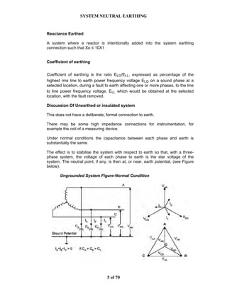
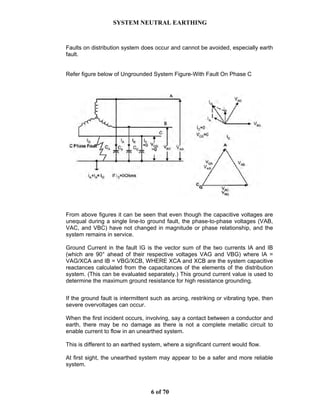
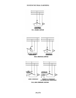
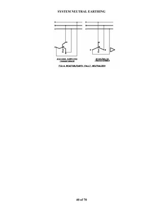
SlideShare a Scribd company logo
SYSTEM NEUTRAL EARTHING
1 of 70
1.0 SYSTEM NEUTRAL EARTHING INTRODUCTION
The purpose of system earthing is to:-
• limit the difference of electric potential between uninsulated conducting
objects in an area
• provide for isolation of faulty equipment and circuits
• limit overvoltage under various conditions
It is standard practice to earth an electrical system for the purpose of limiting the
potential (with respect to the general mass of the earth) of
• current-carrying conductors forming part of the system, and non-current-
carrying metalwork associated with equipment, apparatus, and
• appliances connected to the system.
The former object is normally essential to the proper operation of the system, and
this aspect is generally known as "system earthing".
The latter concerns the safety of human life, of animals and of property, and this
aspect is sometimes known as "equipment earthing" or “safety earthing).
System earthing should normally be provided at one point usually at the source
end at its neutral point and as such System earth refers to intentional connection
of neutral point to earth.
This is necessary because loads may consist of transformers with delta primaries
or delta connected motors and neutral point may not be readily available. Also
for star connected motors/load transformers, earthing at load end may result in
wide variation in fault current depending upon system operating condition and
selective relaying may be difficult.
Also if the supply neutral point is earthed, the phase to earth voltages under
earth fault condition do not rise to high value. Earth fault protection becomes
easy. Hence it is a universal practice to have a neutral earthing at every voltage
level.
The reason for earthing at one point on each system is designed to prevent the
passage of current through the earth under normal conditions and thus to avoid
the risks of electrolysis and interference with communication circuit.
Equipment earthing refers to connection of non-current carrying metallic parts to
earth .It is quite different from neutral earthing. The non current carrying metal
parts include motor body, switchgear structure, transformer core and tank,
sheaths of cables, body of portable equipment etc
SYSTEM NEUTRAL EARTHING
2 of 70
Equipment Earthing ensures safety as the potential of earthed body does not
reach to dangerously high values since it is connected to earth. Secondly the
earth fault current flow through the earthing readily causes operation of fuse or.
an earth fault relay
The term "earthing" is used in this regard whether or not reliance is placed on the
earth itself as a low impedance return path for earth fault current.
The sub-stations, power stations, factories, and electrical installations need
proper body-earthing and neutral-earthing.
The neutral point and bodies of various electrical equipments are connected to
the earthing system,
The earthing system of a sub-station comprises several tens of earth elertrodes
buried deep into the ground The ground electrodes are usually 40 inm diameter,
2 5 rn long GI. Pipes These are connected to Earthing Mesh below ground level
Earthing Mesh can typically be formed by 40 mm dia mild steel rods spaced at 2
rn x 2 m mesh at a depth of 05 m
Earth resistance of Earthing System of a Power Station and sub-station should
be below 0.5 ohm.
Earth resistance of earthing system of residential building may be as high as 2
ohms.
Larger the installation, lower the earth resistance requirement,
With respect to system earthing, the neutral of star connected 3 phase winding of
transformers can be earthed. The neutral of generator can be earthed.
If neutral point is not available, a separate star-delta transformer is arranged Star
points can be earth Sometimes special earthing transformer having zig-zag
winding and neutral point is provided.
A rule to be followed-provide neutral earthing at every voltage level
SYSTEM NEUTRAL EARTHING
3 of 70
Advantages of the System Neutral Earthing
• Elimination of arcing grounds
• Lesser stresses on insulation during earth fault elsewhere.
• Easy earth fault protection.
Disadvantages of the System Neutral Earthing
• Higher earth fault current This disadvantage can be eliminated by providing
reactance earthing or resistance earthing.
In theory, the main power system networks does not have to be earthed and
sometimes arguments are put forward that an unearthed network may be more
reliable.
In some cases this can be true but, in general,unearthed networks can become
unreliable due to over-stressing of the insulation which surrounds cables or lines.
This can arise due to static, induction or intermittent faults.
In the UK & India and most of Europe, the main power networks are earthed.
For example, in the UK & India, the standards and regulations are in place that
are concerned with connection with earth.
This requires that each part of the power network (i.e. each voltage level) be
connected to earth.
In the case of high voltage systems, the earth connection should be as near as
possible to the source of voltage.
There are a number of ways in which the power system can be operated. These
include unearthed, high impedance earthed and low impedance earthed
arrangements.
These different arrangements are described briefly below in subsequent
sections.
SYSTEM NEUTRAL EARTHING
4 of 70
DEFINITION OF SYSTEM EARTHING
Effectively Earthed:
A system earthed through an earthing connection of sufficiently low impedance
(inherent or intentionally added or both) such that ground fault that may occur
cannot build up voltages in excess of limits established for apparatus circuits, or
systems so earthed. The criteria for meeting these requirements are:
• R0 ≤ X1
• X0 ≤ 3X1 The coefficient of earthing (of such systems ≤ 0.8
The earth fault current expected in effectively earthed system is of the same
order of fault current as is available for the three phase short circuit current (it is
typically more than 60% of three phase fault current)
Solidly earthed:
A system earthed through an adequate earth connection in which no impedance
has been inserted intentionally. ( i.e. a solid metallic connection from system
neutral to earth)
Unearthed:
A system, circuit or apparatus without an intentional connection to earth except
through potential indicating or measuring devices or other very high impedance
devices.
Medium Resistance earthed
A system where a resistance is intentionally added into the system earthing
connection such that R0 ≥ 2Xo.
High Resistance earthed
A system where nearly the highest permissible resistance is inserted in the
earthing connection such that Ro ≤ Xco /3
SYSTEM NEUTRAL EARTHING
5 of 70
Reactance Earthed
A system where a reactor is intentionally added into the system earthing
connection such that Xo ≤ 10X1
Coefficient of earthing
Coefficient of earthing is the ratio ELG/ELL, expressed as percentage of the
highest rms line to earth power frequency voltage ELG on a sound phase at a
selected location, during a fault to earth affecting one or more phases, to the line
to line power frequency voltage. ELL which would be obtained at the selected
location, with the fault removed.
Discussion Of Unearthed or insulated system
This does not have a deliberate, formal connection to earth.
There may be some high impedance connections for instrumentation, for
example the coil of a measuring device.
Under normal conditions the capacitance between each phase and earth is
substantially the same.
The effect is to stabilise the system with respect to earth so that, with a three-
phase system, the voltage of each phase to earth is the star voltage of the
system. The neutral point, if any, is then at, or near, earth potential, (see Figure
below).
Ungrounded System Figure-Normal Condition
SYSTEM NEUTRAL EARTHING
6 of 70
Faults on distribution system does occur and cannot be avoided, especially earth
fault.
Refer figure below of Ungrounded System Figure-With Fault On Phase C
From above figures it can be seen that even though the capacitive voltages are
unequal during a single line-to ground fault, the phase-to-phase voltages (VAB,
VAC, and VBC) have not changed in magnitude or phase relationship, and the
system remains in service.
Ground Current in the fault IG is the vector sum of the two currents IA and IB
(which are 90° ahead of their respective voltages VAG and VBG) where IA =
VAG/XCA and IB = VBG/XCB, WHERE XCA and XCB are the system capacitive
reactances calculated from the capacitances of the elements of the distribution
system. (This can be evaluated separately.) This ground current value is used to
determine the maximum ground resistance for high resistance grounding.
If the ground fault is intermittent such as arcing, restriking or vibrating type, then
severe overvoltages can occur.
When the first incident occurs, involving, say a contact between a conductor and
earth, there may be no damage as there is not a complete metallic circuit to
enable current to flow in an unearthed system.
This is different to an earthed system, where a significant current would flow.
At first sight, the unearthed system may appear to be a safer and more reliable
system.
SYSTEM NEUTRAL EARTHING
7 of 70
In reality a current would flow in the unearthed system, returning via capacitive
coupling to the other two phases.
The capacitive current flowing at the fault point is three times the normal
capacitive current to earth from each phase of the whole system.
The damage due to the first fault is likely to be slight, since the total current is still
relatively small.
However, the current could be sufficient to risk electrocution if someone was to
touch the damaged conductor.
Power companies often find that it is time consuming to locate faults on this type
of system. The introduction of an unearthed system into the many system in the
past thus required a change in the Electricity Supply Regulations.
The probability of a second fault is higher than generally thought, as the voltage
across the remaining insulation will be phase to phase level rather than phase to
earth (i.e. an increase of √3 in magnitude). This will stress the phase to earth
insulation and may cause accelerated ageing and breakdown.
A second fault is likely to involve considerable fault energy and damage. It is thus
important to remove the first fault as quickly as possible.
Resonance can cause over-voltages on this type of system.
The system already has a high capacitance and if a phase conductor is
connected to earth via a connection having a high inductance (e.g. an instrument
transformer), then resonance, high circulating currents and over-voltages can
occur.
An intermittent arcing fault which has a high impedance can cause similar high
voltages leading to equipment failure. This is due to a trapped charge effect on
the neutral.
The charge is progressively built up with each subsequent arc and can produce
voltages which can be sufficiently high to overseers insulation by 6 to 7 times (in
theory), of that occurring at normal voltage. In practice, due to weather
conditions, dust etc., the actual voltages measured have been 3 or 4 times the
normal voltage.
If continuity of supply is an important factor for the distribution system, then an
ungrounded system may have some advantages. However, the insulation
applied between each phase conductor and earth is likely to need increasing to
at least the same as that between different phases, in order to deal with single
phase to ground faults, and the trapped charge scenario.
The reasoning behind the prevalence of unearthed systems in many industrial
facilities thus appears to be historical.
SYSTEM NEUTRAL EARTHING
8 of 70
Old practice, especially in American and some European systems was the use of
unearthed neutral system.
This was adopted for process continuity for which the choice was for an
unearthed system that allowed for the controlled shutdown for fault repairs at a
convenient time, and this was of tremendous value to continuous manufacturing
processes by reducing production losses, equipment damage and outages.
Unearthed systems offer no advantage over high-resistance earthed systems in
terms of continuity of service, and have the disadvantages of
• transient over voltages,
• locating the first fault and
• burn downs from a second ground fault.
For these reasons, they are being used less frequently today than high-
resistance earthed systems, and existing unearthed systems are often converted
to high-resistance earthed systems by resistance earthing the neutral.
Discussion Of Earthed systems
If the earth fault is intermittent (arcing, restriking or vibrating), then severe
overvoltages can occur on an unearthed system.
The intermittent fault can cause the system voltage to earth to rise to six or eight
times the phase-to-phase voltage leading to a breakdown of insulation on one of
the unfaulted phases and the development of a phase-to-earth-to-phase fault.
Overvoltages caused by intermittent faults, can be eliminated by earthing the
system neutral through an impedance, which is generally a resistance, which
limits the earth fault current to a value equal to or greater than the capacitive
charging current of the system.
Once the system is resistance earthed, overvoltages are reduced and modern
highly sensitive earth fault protective equipment can identify the faulted feeder on
first fault and trip one or both feeders on the second fault before an arcing burn-
down does serious damage”
The intentional connection of the neutral points of transformers, generators and
rotating machinery to the earth provides a reference point of zero volts. This
protective measure offers many advantages over an unearthed system,
including:
• Reduced magnitude of transient over-voltages
• Simplified ground fault location
• Improved system and equipment fault protection
• Reduced maintenance time and expense
• Greater safety for personnel
• Improved lightning protection
• Reduction in frequency of fault
SYSTEM NEUTRAL EARTHING
9 of 70
An earthed system has at least one conductor or point (usually the neutral or star
point) intentionally connected to earth.
For reasons of cost and practicality, this connection is normally made near the
position where the three individual transformer phase windings are joined, i.e. the
star point or neutral.
This method is adopted if there is a need to connect line to neutral loads to the
system, to prevent the neutral to earth voltage fluctuating with load.
The earth connection reduces the voltage fluctuation and unbalance which would
otherwise occur.
Another advantage is that residual relays can be used to detect faults before they
become phase to phase faults. This can reduce the actual damage caused and
the stresses imposed on other parts of the electrical network.
The type of earthed system is classified according to the type of connection
provided. The main types are:-
Resistors and/or reactors are deliberately inserted in the connection between the
neutral point and earth, normally to limit the fault current to an acceptable level.
The impedance can, in theory, be high enough that little more fault current flows
than in an unearthed situation.
In practice, to avoid excessive transient over-voltages due to resonance with the
system shunt capacitance, inductive earthing needs to allow at least 60% of the 3
phase short circuit capacity to flow for earth faults.
This form of earthing has a lower energy dissipation than resistive earthing.
Arc-suppression coils, also known as Peterson coils or ground fault neutralisers,
can be used as the earth connection. These are tuned reactors which neutralise
the capacitive coupling of the healthy phases, so that fault current is minimal.
Due to the self-clearing nature of this type of earthing it is effective in certain
circumstances on medium voltage overhead systems, for example, those which
are prone to a high number of transient faults,
Resistance earthing is more commonly used, because it can allow the fault
current to be limited and damp transient over-voltages, if the correct value of
resistance is chosen.
In utility distribution systems in various parts of the world, particularly those at 33
kV and 11 kV, it is common to find 750, 1,000 or 1,500 A and in Neutral earth
resistors (NERs) installed in various combinations to limit the earth fault current.
SYSTEM NEUTRAL EARTHING
10 of 70
In systems with rotating machines like generators and motors, it is common to
use NER at the supply source to limit earth fault current to 25 A, 50 A or 75 A to
limit damage to windings and stator core (core tends to melt down for internal
direct EF between winding and core laminations due to winding insulation falire).
In older days liquid filled resistors were used.
In new installations, it is now more common to use ceramic type resistors. These
require less space, have significantly lower maintenance costs and cool down
more quickly than liquid resistors following the passage of fault current.
Most high voltage supply systems, even in the utility, are earthed. Approval has
been given in recent yers to unearthed overhead line systems in certain countries
but these have only been for small 11 kV & 33 kV systems where capacitive
earth fault currents are less than 4 A and circumstances are such that the system
will not be appreciably extended.
There are two broad categories of resistance earthing: low resistance and high
resistance. In both types of earthing, the resistor is connected between the
neutral of the transformer secondary and the earth. These are :--
• Low resistance earth system with EF current limited to high levels of the order
of 1500 A to 2000 A, which in some cases is limited to full load current of the
source supply transformer full load current.
• High resistance earthed system with earth fault current limited to very low
values of:-
• 25 to 70 A, usually used in distribution supply systems with directly
connected generators and motors. The EF current limit in this case is
selected to ensure the machine stator to core earth fault current is within
the machine internal earth fault current for 100 mili-sec, assuming
instantaneous protection is available to clear internal stator earth fault in
the motor/generator
• 5 A usually used for generator with unit transformer that isolates the
generator from the distribution system as far as zero sequence
impedance path is concerned.
SYSTEM NEUTRAL EARTHING
11 of 70
Discussion Of Resistance earthed system
There are two broad categories of resistance grounding: low resistance and high
resistance.
As far as possible generator neutral should be provided with high value NER to
ensure EF current is limited to as low a value as possible, typically 5 to 10 A such
that the resistive component of NER current is greater the connected system
capacitive charging current.
If the EF current contribution is low sensitive EF protection relay settings are
required.
In cases where generator is directly connected to load distribution bus, the
generator NER should be sized to ensure adequate EF current flows to operated
feeder EF relays for prompt fault clearance and circuit isolation. In such cases
the value of source supply generator EF contribution needs to be increase from
a low value of 5 A to the order of 70 A which is the maximum tolerable EF on
machines that can prevent core melting
Both the 5A and 70 A high resistance earthing scheme practiced in the industries
are discussed in the subsequent sections.
Discussion Of Medium Resistance earthing
Medium Resistance earthing usually is adopted for generating systems
connected directly to load distribution switchgear bus, where both motors and
supply generators are connected typically at voltage levels of 6.6 kV / 11 kV.
The medium resistance method has the advantage of immediate and selective
clearing of the earthed circuit but required that the minimum earth fault current be
large enough, usually 400A or more, to positively accurate earth fault relay.
High resistance earthing is a method that can be applied to obtain transient over
voltage protection without aiding earthing fault relays to each circuit.
When generators are connected directly to a common distribution bus serving
motor loads and other transformer/cable circuits, the role of NER is two fold
• One to limit EF to levels that can be tolerated by the rotating machines
• Other to ensure EF relays in all the circuits see adequate current for them
to pick up and operate to clear the fault.
In such cases it is recent practice to limit NER EF current to a maximum of 70 A,
which is the tolerable EF limit of motors and generators This allows EF relay pick
up to be in the range of 7A to 21 A which is 10 to 30 % of the EF current, the
range allowed for satisfactory EF protection of equipment.
Assuming 1 % as the lowest setting of numerical relays, the maximum ratio of
CTs in the distribution circuits should be of the order of 700/1A to 2100/1A.
SYSTEM NEUTRAL EARTHING
12 of 70
It is usual to provide core balance CT of 50/1A on outgoing motor feeders which
will ensure that sensitive EF relay connected to CBCT will have a pick up of 2.5A
even if an ordinary numerical EF relay with minimum 5 % EF pick up setting is
used.
CBCTs are useful to ensure EF relay pick up is sensitive enough even though
the EF current is limited to as low a value of 25 to 70 A.
The recent high resistance earthed system practices are shown in figures
attached for different scenarios
In both types of grounding, the resistor is connected between the neutral of the
source generator and/or the source supply transformer secondary and the earth
ground
The objective of the resistance earthing is to limit EF current to a value that can
be considered :-
• Low enough to reduce damage to machines during internal EF. Typical EF to
be limited for generators and motors connected to a common bus would be of
the order of 70 A clearled in instantaneous protection clearance duration of
maximum 100 milli-sec.
• High enough to operate EF relays with adequate sensitivity such as to cover
for a high % of phase to the neutral. winding protection. Typically for 90 %
machine winding protection coverage, the EF relay current pick up should be
10 % of the minimum EF current. The maximum EF current sensitivity should
not be allowed to increase over 30 % of the minimum EF current.
The generator and motor EF current versus withstand time curves for reference
are given in figures below:-
SYSTEM NEUTRAL EARTHING
13 of 70
SYSTEM NEUTRAL EARTHING
14 of 70
Typical Internal Stator Earth Fault Current withstand limit
of generators & motors
Typical External Earth Fault Current withstand limit
of generators & motors (time in second on the x axis)
Time in second
SYSTEM NEUTRAL EARTHING
15 of 70
Discussion Of High resistance earthing.
Generators, especially larger ratings should not be exposed to high EF currents.
The EF should be limited to as low a value as possible. This is not possible for
smaller generators that are directly connected to the distribution system bus as
the generator in this case should contribute enough EF current to operate
distribution feeder earth fault relays for fault clearance and isolation.
However larger generators are usually connected to the distribution system via
their dedicated step up or step down generator transformer that have delta
connected winding on the generator side with star connected winding on the
distribution side where medium resistance earthing with higher EF current
contribution can be followed to satisfy distribution system EF protection
requirements.
The use of Delta-Star unit generator transformer for each generator actually
isolates the generator circuit from the distribution system as far as earth fault on
the distribution system is concerned
Due to isolation of zero sequence circuit between the generator and the
distribution system, the generator earth fault could be limited to as low as value
as possible. This is because generator does not contribute to the external
distribution system EF and hence plays less role in the achievement of fast and
selective earth fault relaying on the external distribution system.
When continuity of operation is desired, downtimes due to dismantling of
generator stator and rotor for factory repairs is not acceptable.
A medium resistance generator earthing with 70 A EF limit is considered to be
too high from this point of view.
In order to improve system integrity by preventing generator outage and
downtime due to core damage on generators, it is important that generator EF
current is limited to low value. For such cases each generator neutral is earthed
through a single phase distribution transformer with a secondary loaded resistor.
The resistor will be sized high to limit the generator EF to as low as value of 5 to
10A such that the resistive component of the generator EF current is greater than
the total capacitive current in the generator circuit to prevent core damage and to
prevent production of high generator circuit transient over voltages in the event of
arcing fault
SYSTEM NEUTRAL EARTHING
16 of 70
Discussion Of Low Resistance Earthing
The practice in the past was to adopt low resistance earthing and this was before
sensitive numerical protection relays were used.
A high earth fault was required to ensure EF protection relays clear the fault but
this practice was a compromise that accepted the fact that internal motor or
generator EF will result in damage to the respective motor/generator.
Concerns of high internal machine stator EF are :-
• Excessive arcing to the machine core burns the stator iron core laminations
at the point of fault and results in core welding.
• Replacement of faulty conductor may not be a very serious matter but
damage to the core cannot be ignored, since the welding of laminations
would result in local overheating.
• The fused metal can sometimes be cut away and replaced, but if severe
damage has occurred, it may be necessary to rebuild the core down to the
fault., which would involve extensive dismantling of the winding.
Low resistance grounding of the neutral limits the ground fault current to a high
level (typically 50 amps or more) in order to operate protective fault clearing
relays and current transformers. These devices are then able to quickly clear the
fault, usually within a few seconds.
The importance of this fast response time is that it:
• Limits damage to equipment,
• Prevents additional faults from occurring,
• Provides safety for personnel,
• Localizes the fault.
The limited fault current and fast response time also prevent overheating and
mechanical stress on conductors.
Note that the circuit must be shut down after the first ground fault.
Low resistance grounding resistors are typically rated 400 amps for 10 seconds,
and are commonly found on medium and high voltage systems
The main drawback of low resistance earthed system is the value of EF that can
be too high resulting in considerable damage to generator/motor core during
internal stator EF. This can result in generator/motor downtime associated with
core damage that would need stator and rotor dismantling leading to costly and
long duration factory repairs
SYSTEM NEUTRAL EARTHING
17 of 70
Solidly earthed system
This is the most common arrangement, particularly at low voltage.
Here the neutral/earth connection is through an adequate connection in which no
impedance has intentionally been added.
.For LV systems the practice is to solidly earth the neutral without any intentional
earthing resistance. The main purpose being to limit voltage above earth at any
point of the LV system for personnel safety reasons.
The disadvantage of this arrangement is that the earth fault current is normally
high, but the system voltages remain suppressed or low under fault conditions
In distribution systems with LV motors, the EF current will be higher than the
values that can be tolerated by the motor. But since motors are of smaller
ratings, this aspect of damage is compromised in favour of personnel safety..
For grid in-feed system voltages above 36 kV, the neutral point of transformers
should be solidly earthed, unless otherwise required by the public utility.
Grid in-feeds with solidly earthed neutral points can result in high earth fault
currents flowing in the general mass of earth in the vicinity of the substation.
They must be designed such that these currents do not result in dangerous step
and touch potentials. Detailed guidance is given in IEEE Standard 80 (IEEE
Guide for Safety in AC Substation Grounding)
Transformer feeders to HV switchboards with a system voltage not exceeding 36
kV may be low resistance earthed within typical industrial or even utility
distribution networks, however, where the distribution network is predominantly
cable, most of any potential earth fault current will flow in cable sheaths.
Standard cable sheath have limited EF current withstand. If standard cables are
to used then transformers iupto 33 kV may be low resistance earthed with EF
current limited to full load current of transformer or maximum of 1200 to 1500 A.
Where cables are procured with additional copper braiding forming sheath with
higher cross sections and able to withstand high EF current then 33 kV systems
can be solidly earthed.
HV & EHV systems > 132 kV are usually solidly earthed
SYSTEM NEUTRAL EARTHING
18 of 70
Earthing Schemes for Multiple Generators
If multiple generators are directly connected to a switchboard and each is
earthed via its own dedicated resistor, then zero sequence harmonic currents
(principally, the third harmonic) may possibly circulate through the neutral-earth
connections of the parallel operating machines. The magnitude of this circulating
current will depend on:
• the difference in magnitude and phase of the triplen harmonic voltages in the
stator voltage waveform of the respective generators operating in parallel (if
the waveforms are not perfectly sinusoidal);
• the magnitude of neutral-earth resistances and of stator reactances (at the
relevant harmonic frequency) of the respective generators.
Consequently, harmonic current can circulate in the neutral resistors of dissimilar
machines operating in parallel, and also between identical machines operating in
parallel if the harmonic voltage is sufficiently large and/or the electrical loading of
the identical generators is sufficiently different.
If the sustained circulating current is such as to exceed the thermal rating of the
resistor, then the current may be reduced by increasing the ohmic value of the
resistor by adopting high resistance earthing for each generator.
A common bus connected earthing transformer (ET) for bus medium resistance
earthing will be required for schemes with multiple generators where each
generator is high resistance earthed). This may be done to ensure the resultant
earth fault current is at least 3 to 10 times the setting current of any earth fault
relay on the relevant HV system.
Various generator specification and standards states the maximum acceptable
harmonic voltages in the stator voltage waveform of synchronous generators.
Where generators of dissimilar ratings, characteristics or loadings are to be
operated in parallel so as to give rise to circulating currents in the above-
mentioned earthing resistors that would exceed the thermal rating of the
resistors, then the HV system shall be earthed via one earthing resistor only.
Each generator shall then be provided with a suitable switching device, i.e.,
remotely operated circuit breaker or latched contactor) to facilitate connection of
any machine to the single earthing resistor. During normal operation, only one
generator shall be connected to the resistor. If the generator so connected is
tripped for any reason, an alarm is required to prompt manual intervention to
close the neutral earth switching device of one of the other operating generators
to facilitate earthing of the system.
Where generators are connected to the main switchboard via individual
generator step-up transformers, each generator neutral point shall be individually
earthed through a single phase distribution transformer with a secondary resistor.
The resistor shall be rated to limit the generator earth fault current to 10 A, or to
3 x Ico where Ico is the per-phase capacitive charging current, whichever is the
greater.( In this respect the per-phase capacitive current is that due to the
generator stator windings, generator transformer LV winding, and generator main
cable/connections).
SYSTEM NEUTRAL EARTHING
19 of 70
Each earthing transformer and resistor shall be rated to withstand the respective
earth fault currents for a duration of not less than 10 s. Longer withstand times
may be required,depending on the earthfault protection system applied.
Common Star Delta Earthing Transformer Details
The earthing of a medium voltage network neutral or the protection of generator
can be carried out using a common zig zag earthing transformer or a star-delta
earthing transformer (also called homopolar generator) associated with a
medium value NER connected on the low voltage end.
This so called homopolar generator is a three phase transformer with two
windings and free flux (generally). This transformer has a primary winding
(medium voltage) which is star connected with its neutral connected to the earth.
The secondary is delta connected on a resistor.
During normal operation, the voltage across the terminals of the secondary is
zero and no current flows through the resistor.
When a fault arises on a phase, neutral point’s displacement on the primary
makes appear an homopolar voltage on the terminals of the secondary (see
diagrams ) :the current flows through the resistor.
Normal operation Earth fault Condition
The value chosen for this resistor, and characteristics of the transformer
(inductive & resistive drops), determines the earth fault current at the medium
voltage. In the event of a less severe fault, the neutral displacement is less and
the fault current in the low and medium voltage end are lees in proportional to the
neutral displacement.
SYSTEM NEUTRAL EARTHING
20 of 70
SYSTEM NEUTRAL EARTHING
21 of 70
Various GENERATOR Earthing Schemes Adopted In Practical Industrial
Sytems
The are shown individually in SLDs in subsequent pages
• Medium resistance system for industrial distribution system
predominated by motor loads with source supply generator directly
connected to the same distribution switchgear bus
Requirement For NER Selection In Above Scheme
• Generator is directly connected to the distribution system and
hence its EF current contribution should be high enough to
operate EF relays so as to clear and isolate faults on the
distribution feeders, but at the same time the EF current
should be low enough to prevent motor/generator core
damage due to internal stator earth faults in them.
SYSTEM NEUTRAL EARTHING
22 of 70
• Medium resistance system with common bus earthing with high
resistance used for generator earthing in a industrial distribution
system predominated by motor loads with source supply generator
directly connected to the same distribution switchgear bus
Requirement For Common RT With Medium NER Selection In
Above Scheme
• Generator is directly connected to the distribution system and
hence its EF current contribution should be high enough to
operate EF relays so as to clear and isolate faults on the
distribution feeders, but at the same time the EF current
should be low enough to prevent motor/generator core
damage due to internal stator earth faults in them.
Requirement For Individual High NER Selection For Each
Generator In Above Scheme
• Generator could be unearthed in the above scheme under
normal system operation, but a high NER is selected for each
generator to ensure generator will not be unearthed during its
start up when the generator circuit CB will be open. The value
of EF from generator is low as it does not add to the common
earthing transfer NER EF contribution limited to medium EF
current value required for reasons cited above.
SYSTEM NEUTRAL EARTHING
23 of 70
• Low To Medium resistance system with MULTIPLE GENERATORS
with only one generator neutral circuit switched on to common NER
connected to common neutral earth switchgear or otherwise
SYSTEM NEUTRAL EARTHING
24 of 70
Classification of systems based on types of system earthing and based on
protection in case of indirect contact
Dangerous touch voltages must be prevented from occurring or persisting in the
event of a fault (fault to frame).The limit values for touch voltages are:-
• 50 V ac
• 120 V dc
The earthing systems are classified internationally as:-
• TN System classified further as:-
o TN-S System
o TN-C System
o TN-C-S System
• TT System
• IT System
• Other systems as per IS 3043
General applications of these earthing systems used internationally and in in
India are as follows:
Basic Types Internationally Accepted
TN-S Internationally Accepted Systems With Separate
Neutral & Protective conductors throughout the
system
240 V Single phase domestic /
commercial supply
TN-C Internationally Accepted Systems With Combined
Neutral & Protective conductors throughout the
system
‘----------------------------
TN-C-S Combination of international TN-S & TN-C in
different parts of the system
415 V Three phase domestic /
commercial supply
TT 415 V three phase industrial
supply
IT TT System in which all exposed conductive parts
are connected to earth electrode which is
electrically independent of the source earth. Single
Phase TT system not followed in India
415 V three phase industrial
systems where process
continuity is of more impotanc
Indian Types As Per IS 3043
INDIAN TN-S Same as International TN-S system above but with
an independent earth electrode within the
downstream load centre consumer’s premises is
required in this system
415 V Three phase domestic /
commercial supply
INDIAN TN-C Same as International TN-C system above but with
an independent earth electrode within the 3 phase
downstream load centre consumer’s premises is
required in this system
415 V Three phase domestic /
commercial supply
T-TN-S The consumer’s installation, a TN-S system
receiving power at a captive substation through a
delta connected transformer primary
For bulk supply at 6.6 kV & 11 kV
Each of the systems configurations are shown in diagrams in subsequent pages.
SYSTEM NEUTRAL EARTHING
25 of 70
• TN-S System is one in which the neutral and protective earthing system
are separate
TN-S as Per IS 3043 (Same As International One)
Indian TN-S as per IS 3043
SYSTEM NEUTRAL EARTHING
26 of 70
• TN-C System is one in which the neutral and protective earthing system
are combined
Indian TN-C as per IS 3043 (same as international TN-C)
SYSTEM NEUTRAL EARTHING
27 of 70
• TN-C-S System is one in which combination of both TN-S & TN-C are
adopted in different parts of the system
TN-C-S as per IS 3043
SYSTEM NEUTRAL EARTHING
28 of 70
• TT System in which all exposed conductive parts are connected to
earth electrode which is electrically independent of the source earth.
Single Phase TT system not followed in India
TT System as per IS 3043
SYSTEM NEUTRAL EARTHING
29 of 70
• IT System in which all exposed conductive parts are connected to
earth electrode with source is isolated from earth or may be earthed
through high impedance.
IT System as per IS 3043
SYSTEM NEUTRAL EARTHING
30 of 70
• Indian TN-S system as per IS 3043
• Indian T-TN-S system as per IS 3043
SYSTEM NEUTRAL EARTHING
31 of 70
RECOMMENDED PRACTICE
• It is necessary to provide system neutral earthing at each voltage level except
where a certain voltage level is intentionally kept unearthed.
• Recommended type of earthing for various systems is given in Table I.
• Recommended generator earthing applications are given in Table II.
• Location of earthing connection:- Earthing should normally be provided at
the source end. This is necessary because loads may consist of
transformers with delta primaries or delta connected motors and neutral point
may not be readily available. Also earthing at load end may result in wide
variation in fault current depending upon system operating condition and
selective relaying may be difficult.
• Generator earthing:- The maximum stress which a generator is normally
designed to withstand is that associated with the currents of a three phase
fault at the machine terminals. Because of relatively low zero sequence
impedance inherent in most synchronous machines, a solid line to earth fault
at machine terminals results in a machine winding current higher than three
phase fault current. Therefore some impedance in the generator neutral
earthing is necessary.
• Multiple power source:- When there are two or more major bus sections,
each bus section should have at least one earthed neutral point.
When there are two or more generators at one station, only one neutral
earthing resistor is some times used.
Each power source is then connected to the resistor through a neutral bus
and neutral switching equipment (preferably breakers) it is desirable in such
cases to operate with only one generator neutral breaker closed at a time to
eliminate any circulating harmonic or zero sequence currents.
In the case of multiple transformers all neutral isolating devices may be
normally closed because presence of delta connected windings (which are
nearly always present on at least one side of each transformer) minimizes
circulation of harmonic current between transformers.
• Zig-Zag earthing transformer:- Where one machine only is tied to a bus
with feeders requiring a permanent system earthing, generator neutral
earthing of any type is usually inadequate. Here removal of the generator
from service for any reason also removes the only earthing point. This also
may be the case with several machines on the bus where, for most economic
scheduling of generation or other reasons, all the generators on that bus may
at some time be shut down. In such cases an earthing transformer should be
provided on the generator bus. Either a zig zag or wye-delta transformer may
be used. For a given short time current rating, the zig-zag earthing
transformer is somewhat lower in cost and more frequently used. As an
SYSTEM NEUTRAL EARTHING
32 of 70
alternative, a more readily available start/delta transformer of adequate rating
(probably in stock) may be used.
• Parallel operation of Transformer:- When an earthed star/star transformer
with delta tertiary is operated in parallel with similar transformers with neutrals
unearthed, the rating of the tertiary of the former should be checked for being
adequate to carry zero sequence current under fault condition. The usual
33% rating of the tertiary winding may not be adequate.
• Merits and demerits of various earthing systems
EARTHING
TYPE
MERITS DEMERITS
Solid earthing Fast relaying
No over voltage
More damage at the point of
fault
Low resistance
earthing
Graded protection
possible.
Less damage at the point
of fault.
Overvoltage on healthy
phases
Higher cost
High resistance
earthing
No damage to the
equipment
Continuity of supply
possible with fault
hanging in the system
High overvoltages on healthy
phases
Graded protection not
possible
Protection system is costly
:
SYSTEM NEUTRAL EARTHING
33 of 70
• Comparative Performance For Various Conditions Using Different
Earthing Methods
Characteristics Ungrounded Solid
Grounded
Low
Resistance
Grounded
High
Resistance
Grounded
Immunity To Transient Voltages Worst Good Good Best
Ease Of Ground Fault Protection Worst Good Better Best
Equipment Protected Against Arc Fault
Damage
Worst Poor Better Best
Safety To Personnel Worst Better Good Best
Service Reliability Worst Good Better Best
Maintenance Cost Worst Good Better Best
Continued Production After First Ground
Fault
Better Poor Poor Best
Ease of Locating First Ground Fault Worst Good Better Best
Relay Co-ordination Not Possible Good Better Best
73% Increase in Voltage Stress Under L-G
Fault Conditions
Poor Best Good Poor
Two Voltage Levels on the Same System Not Possible Best
Not
Possible
Not
Possible
Reduction in Frequency of Faults Worst Better Good Best
First High Ground Fault Current Flows Over
Grounding Circuit
Worst Better Good Best
Potential Flashover To Ground Poor Worst Good Best
• Expected earth fault currents:- The typical level of available earth fault
current that can be expected from various types of system earthing are as
follows:
Solidly earthed, effectively
earthed, earthed for serving
line to neutral loads
Same order of fault current as is available for
the three phase short circuit current (more than
60% of three phase fault current)
Reactance earthed Nearly as high as the three phase short circuit
current (25% to 60% of 3 phase fault current)
Low resistance earthed 25A to 70 to 100 amperes depending on value
of resistance.
Medium resistance earthed 200 A to several thousand amperes
High resistance earthed Upto 10A level ( current though resistor more
than system charging current)
SYSTEM NEUTRAL EARTHING
34 of 70
The medium resistance method has the advantage of immediate and
selective clearing of the earthed circuit but require that the minimum earth
fault current be large enough, usually 400A or more, to positively accurate
earth fault relay.
High resistance earthing is a method that can be applied to obtain transient
over voltage protection without aiding earthing fault relays to each circuit.
• Criteria for limiting transient over voltages:- In resistance earthed
systems, the resistor earth fault current should be at least equal to, but
preferably greater than the charging current of the system.
In reactance earthed system the ratio Xo/X1 ≤ 10 where Xo is the zero
sequence inductive reactance of the system including that of the neutral
reactor.
Where a combination of earthing transformer and neutral earthing resistor is
used, the earthing transformer impedance should be low relative to the
neutral resistance. Ro / Xo ≥ 2, where Ro and Xo are inclusive of neutral
resistor and earthing transformer.
• Arrestor Application:- Arrester application discussed below is only to bring
out arrester ratings required with adoption of different methods of system
neutral earthing. ……..
The minimum required arrester rating is the maximum operating voltage
times coefficient of earthing, which is 80% for effectively earthed systems,
and more than 80% for non-effectively earthed or unearthed systems. The
earth fault current in this case is more than 60% of three phase fault current.
Systems, which employ some form of resistance system earthing, are non-
effectively earthed systems having coefficient of earthing of 100% for arrester
application purposes.
Many high voltage systems may exhibit coefficients of earthing as low as
70% and certain multi earthed distribution systems may even slightly less.
It may not be practicable to provide an earthing transformer of the size and
impedance necessary to give an Xo/Xl ratio of 3 or less. However, if the
generator neutral is also earthed by means of a suitable reactor, the earthed
neutral type (80%) of arrester may be applied at the machine terminals.
SYSTEM NEUTRAL EARTHING
35 of 70
EQUIPMENT SIZING
HIGH RESISTANCE EARTHING (TRANFORMER / RESISTOR
COMBINATION)
• EARTHING TRANSFORMER ET)
• VOLTAGE = VLL
• IMPEDANCE (Xep) = (Xo / X1) ( VLL KV)2
---------------------------------
3 PHASE FAULT MVA
• CURRENT (Ie) = 3E / X1 + X2 +X0 + 3 Xep
(E = VLG Xep = REACTANCE OF EARTH RETURN PATH)
• DURATION = 10 SEC OR 60 SEC OR CONTINUOUS (FOR HIGH
RESISTANCE EARTH ONLY)
• EARTHING RESISTOR
R = 706
-------
CN2
C = CAPACITANCE TO EARTH IN µF / PH
N = TRANSFORMATION RATIO OF ET
• VOLTAGE = TRANFORMER SEC VOLTAGE
• TIME = 10 SEC OR 60 SEC
MEDIUM RESISTANCE EARTHING
R = VPH
---------
FAULT CURRENT
FAULT CURRENT IS GENERALLY LIMITED TO 200 TO 1000 A.
DURATION = 10 SEC OR 60 SEC.
REACTANCE EARTHING
REACTANCE Xn = X1 – X0
3
X1 = GENERATOR POSITIVE SEQUENCE SUB TRANSIENT
REACTANCE
X0 = GENERATOR ZERO SEQUENCE REACTANCE
SYSTEM NEUTRAL EARTHING
36 of 70
THERMAL CURRENT RATING
3E
Ie = ------------------------------------------------------
X1 + X2 + Xo + 3 (X n + X ep )
NOTE 1.
FOR X1 OF GENERATORS AND SYNCHRONOUS MOTORS USE
TRANSIENT REACTANCE FOR X2 OF GENERATORS,
SYNCHRONOUS AND INDUCTION MOTORS USE SUB
TRANSIENT REACTANCE ( X1, X2, X0 ETC REFER TO - SOURCE
TO POINT TO FAULT REACTANCE)
TIME - 10 SECONDS
60 SECONDS
SYSTEM NEUTRAL EARTHING
37 of 70
TABLE I
Sl.
#
System Recommended Method of
Earthing
Ref.
Fig
Remarks
1 Industrial Plants
a) Up to 415V Solidly Earthed 1 Earth connector should be of
adequate capacity
b) Above 415V up to
11kV
Medium Resistance
Earthed
2 Limit Earth fault current to
largest feeder current &
permit tripping of circuit.
c) Above 11kV Solidly earthed Earth Connector should be of
adequate capacity
2 Auxiliary Systems of
Power Plants
i) Medium Resistance
Earthed
2 Resistance to limit earth fault
current to transformer full
load current & permit tripping
of circuits.
ii) High Resistance
Earthed
3 When continued operation
(until it is convenient to locate
and correct the fault) is
desired.
3 Synchronous
Generators
a) Unit System i) High Resistance
Earthed
3 Current limited to 1.5 times
capacitive charging current
(usually distribution
transformer and secondary
resistor)
b) Several machines
and/or feeders on
the bus
ii) Reactor Earthed 4 Earth fault current to be
limited to 25% -60% of three
phase fault current to prevent
serious transient over voltages
( XO ≤ 10X1 ) and permit
selective relaying.
4 Transmission System a) Effectively earthed 1
b) Earth fault neutralizer 3 When it is desired to limit the
earth fault current and to
reduce switching surges to
safe values.
SYSTEM NEUTRAL EARTHING
38 of 70
TABLE II
Solid Reactor Resistor
NGT +
NGR
Isolated
Neutral
and
Zig-
Zag
NGT
Remarks
SM P S P NS Note 1LV BUS
NO LV
FEEDER MM P S P NS Note 2
With CEIG
Approval
SM P NS P NS Note 1LV BUS
WITH
FEEDER MM P P P NS Note 2
SM NS P P NS NS
HV BUS
NO HV
FEEDER MM NS P
P
(With
Neutral
Bus)
NS NS
SM NS P P NS S*
HV BUS
WITH
HV
FEEDER
MM NS P
P
(With
Neutral
Bus)
NS S*
If
sufficient
cable
capacitance
is available
UNIT
SYSTEM
NS
P (For
utility
Generators
only)
P
P (For
utility
Generators
only)
NS
NOTE1 FOR FAULT LEVEL GREATER THAN 40 KA FOR EXISTING SYSTEMS
NOTE 2 FOR FAULT LEVEL GREATER THAN 70 KA FOR NEW SYSTEMS
S - SATISFACTORY
P- PREFERRED
NS- NOT SUITABLE
SM - SINGLE MACHINE
MM - MULTIPLE MACHINES
SYSTEM NEUTRAL EARTHING
39 of 70
SYSTEM NEUTRAL EARTHING
40 of 70
SYSTEM NEUTRAL EARTHING
41 of 70
Figure 5
SYSTEM NEUTRAL EARTHING
42 of 70
Calculation of industrial distribution supply system Medium NER
Basis Of Calculation
• Compared to isolated neutral and distribution transformer (high resistance)
methods of grounding, the medium resistance grounding for the plant, say
typically 6.6 kV.auxiliary electrical system has the advantages of lower
transient over-voltages, and more reliable protective relaying.
• The Supply transformer secondary 6.6 kV neutral or supply source generator
6.6 kV neutral should thus be medium resistance earthed in order to limit 6.6
kV system earth faults (EF) to low values such as to restrict excessive
damage to 6.6 kV equipment (especially to rotating machines like 6.6 kV
motors due to core melt down possibility in case of higher earth faults)
bearing in mind the fact that earth faults are not too low to result in non
operation of earth fault protection (because of lower earth fault currents
expected as compared to low resistance earthing).
• In the medium resistance 6.6 kV system earthing method, the earth fault
current should be limited to a value that can be reliably detected
instantaneously and cleared immediately by all 6.6 kV circuits whilst at the
same time ensuring their respective EF relay setting is not below the
expected charging capacitance current of the system.
• It has been observed that with the addition of even small resistance at the
neutral, the line to neutral voltage during line to ground fault rises to line to
line voltage. But the transient over voltages can be kept to lower side if the
magnitude of the resistive component of earth fault current is increased such
that the resistive loss during EF is greater than capacitance loss in the
system during the fault.
SYSTEM NEUTRAL EARTHING
43 of 70
• With respect to above note the following aspects for 6.6 kV system NGR :-
o The 6.6 kV incomer transformer circuit EF relay setting should not
exceed 30 % of the EF current and the outgoing motor/transformer 6.6 kV
EF relay setting minimum sensitivity should be 10 % of the EF current.
o Any 6.6 kV circuit EF relay setting should not be lower than the system
capacitive charging current which for a system with 9 transformers, 2
motors and 1 km of 6.6 kV cables is not expected to be greater than 3 to
5 A at 6.6 kV (assuming 1 A for 1 km of 6.6 kV cables, 0.1 A for two 6.6
kV motors and total of 1 A for transformer capacitance charging current
for 9 transformers including other margins. For Thumb Rule Values Refer
Appendix attached).
o Say the largest incoming 6.6 kV circuit CT ratio will be 2000/1A,
Assuming a 1.00 % setting available for numerical earth fault relays at
least 67 A earth fault current contribution will be required for satisfactory
operation of the earth fault protection connected to the largest incoming
feeder 2000/1 A CT. This ensures the largest incomer feeder EF setting is
very well below 30 % of the total EF current for achieving the desired EF
sensitivity. (Note for 2000/1A CT, its respective feeder EF relay setting
can be set to 20 A (1.0 % of 2000 A) which is 30 % of the total EF Current
expected of 67 A.
• For outgoing circuits with lower CT ratings, better EF sensitivity (10 % of EF
current) can be achieved with 67 A EF current.
• While selecting the value of ground fault current, it has been observed that
with 67 Amps 6.6 kV ground fault current, fast and sensitive earth fault
protection can be provided without mal-operation due to capacitive current
charging effect
• Also 67 A EF current is safely within the tolerable value of generators and
motors for internal stator EF.
• The earthing resistor will be of the heavy duty, non inductive, rustless,
oxidation resistant, jointless and unbreakable stainless steel grid type. The
resistor willl be housed in a vermin proof, water proof & weather proof
protected metal clad enclosure suitable for outdoor installation.
• Since any circuit EF relay will isolate the feeder within a few seconds on the
occurrence of ground fault, a time of say 10 seconds may be taken for the
NGR short time rating, the 6.6 kV neutral earthing resistor should be capable
of carrying rated 67 A earth fault current for a period of at least 10 seconds
without damage to itself or its enclosure. The earthing resistor will be
complete with supporting insulator/structure and insulated for 7.2kV above
earth for 6.6 kV resistor.
SYSTEM NEUTRAL EARTHING
44 of 70
Calculation of industrial distribution supply system Medium NER
Rated MVA of HV Transfo. = 20.00 MVA
Voltage Ratio of HV Transfo. = 33kV / 6.9 kV kV
NGR connected to Winding (kV) = 6.6 kV
Vector Group of HV Transfo = Dyn1
NER Current rating = 67 A
( As per Basis Discussed In this sizing report)
System Rated Voltage = 7.2 kV
Hence
Resistance value of NER = 6.6 / 1.732 / 67
= 56.873 Ohm
NER Current rating = 67 A
NER Rated Maximum Voltage = 7.2 kV
NER Nominal Voltage 6.6 kV
NER Design Ambient Temperature = 55 0
C
Resistance value of NER = 56.873 Ohm
Material of Construction Stainless Steel (SEE Note Below)
Temperature rise 250 °C over ambient temp 50°C
Degree of protection = IP - 55
Location of installation = Outdoor
Note:- The earthing resistor shall be of the heavy duty, non inductive, rustless,
oxidation resistant, jointless and unbreakable stainless steel grid type. The resistor
willl be housed in a vermin proof, water proof & weather proof protected metal clad
enclosure suitable for outdoor installation.
SYSTEM NEUTRAL EARTHING
45 of 70
Generator High Resistance Earthing Transformer & NER Calculation
Basis Of Design
• In order to protect stator core from damage during internal stator earth fault,
it is necessary to limit stator earth fault to as low a value that is
practicable.
• Generators connected to the distribution system, through unit
generator transformer dedicated to each generator, can be treated as
an isolated system which is not influenced by the earthing
requirements of the distribution system which in this case is
established through tdistribution side transformer medium earthing
resistance.
• The industry wide practice for such generators is to use a 11 kV
neutral earthing transformer suitably rated with secondary winding
designed for 240 V or so and loaded with a resistor of a value which
when referred to the primary will pass a low earth fault current of say 5
to 10 A.
• The Neutral earthing resistor connected shall be of low ohmic value of
rugged construction while still presenting a high equivalent value in the
generator 11 kV neutral circuit
• The Neutral resistor shall be incorporated to prevent the production of
high transient over voltages (TOVs) in the event of an arcing earth fault
which it does by discharging the bound charge in the circuit
capacitance.
• To prevent transient over voltages, it is necessary to ensure the
equivalent resistance in the stator circuit should not exceed the
impedance at system frequency of the total summated capacitances of
the three phases of the generator circuit.
• In this respect the resistive component of stator EF current should not
be less than (not < than) the residual capacitance current ( 3.Ico ) in
the generator 11 kV circuit upto generator unit tranformer.
• For Selecting Earthing Transformer, it is necessary to ensure it never
becomes saturated otherwie a very undesirable condition of ferro-
resonance may occur.. In this respect it is usual to select transformer
havinng a primary winding with knee-point voltage (Vk) = to 1.3 x
generator rated line voltage of 11000 V (11 kV)
SYSTEM NEUTRAL EARTHING
46 of 70
Generator High Resistance Earthing Transformer & NER Calculation
Selection Of EF Current Limit
Generator Data
Generator Rating = 50 MW
Rated Gen kV 11 kV
Maximum Overvoltage 14.3 kV
Generator Transformer Data
Ratio 11/132 kV
Total Capcitance Per Phase
Gemerator 0.22
Micro-Farad
Typical
Generator Connections 0.001
Micro-Farad
Typical
Generator-Transformer 11 kV 0.006
Micro-Farad
Typical
11 kV Cable 100 m 0.0003
Micro-Farad
Typical
Surge Suppressor Capacitance 0.25
Micro-Farad
Typical
Total 0.4773
Micro-Farad
Typical
TOTAL RESIDUAL CAPACITANCE 1.4319
(3.C) Micro-
Farad
TOTAL RESIDUAL CAPACITIVE IMPEDANCE 2222.99 Ohm
(10^6 ) / (3.w.C)
Neutral Earthing Resistor
The Effective Resistance Should Be Made Equal To Residual Capacitive
Impedance (2222.99 Ohm calculated above) To Ensure TOV Is Controlled
Then Resistive Component Of EF 2.8569 A
The Actual Fault Current Will Contain Equal Resistive & Capacitive Components &
The Net EF Current Will Be Sqrt (Ir^2+Ic^2)
4.04026 A
SYSTEM NEUTRAL EARTHING
47 of 70
Generator High Resistance Earthing Transformer & NER Calculation
Neutral Earthing Distribution Transformer (Neutral ET or N ET) & NER Sizing
N ET
Transfo Primary Vk (Knee Point Voltage) 15.000 kV
Applied kV On N ET During EF 6.351 kV
Applied kV On N ET During EF With Field
Forcing 8.256 kV
Increase in Neutral EF Current 3.714 A
Maximum N ET Loading Under Above Condition 55.709 kVA
Considering 30 sec duty, the N ET Can Have 6
Times Short Term 30 Sec Overload Withstand
With kVA Considered Based On Maximun EF
Amp & Knee Point kV
9.285 kVA
10.000 kVA
N ET Secondary Rating
Consider Secondary Knee Point Of 240.000 V
Maximum Secondary Current 232.123 A
N ET Secondary Loading Resistor
Equivalent Neutral Primary Resistor 2222.99 Ohm
Actual Secondary Loading Resisor Based on 15
kV / 250 V N ET
0.56909 Ohm
N ET Secondary Amp 41.6667 A
Type N ET Cu Loss 310 Watt
Type N ET Resistance Due Cu Loss 0.17856 Ohm
Therefore N ET Secondary Loading Resistor
0.39053 Ohm
Rated N ET Secondary Resistor Ampere For 30
Seconds
232.123 A (For 30 Sec)
,(1.3*2.857*11000/240)
SYSTEM NEUTRAL EARTHING
48 of 70
Generator High Resistance Earthing Transformer & NER Calculation
Generator High Resistance Neutral Earthing Transformer Reactance
Calculation
Typical % X Of N ET 4 %
Typical X pu Of N ET 0.04 PU
N ET Rating (Base kVA) 10 kVA
N ET Rating (Base MVA) 0.01 MVA
Base kV 0.25 kV
X Base 6.25 Ohm
N ET X in Ohm 0.25 Ohm
N ET R in Ohm AS Calculated Above 0.17856 Ohm
X/R Ratio Of N ET 1.40009
(This Should
Not Exceed 2)
Summary Of Requirements
N ET Rating 10 kVA
N ET Ratio ,15000V/240V
N ET Secondary Loaded Resistor 0.39053 Ohm
N ET Secondary Loaded Resistor 30 Second
Current Rating 232.123
A For 30
Second
N ET X/R Ratio 1.4 (Not > 2.)
SYSTEM NEUTRAL EARTHING
49 of 70
APPENDIX EXPALAINING NEUTRAL INVERSION OR FERRORESONANCE
SYSTEM NEUTRAL EARTHING
50 of 70
SYSTEM NEUTRAL EARTHING
51 of 70
APPENDIX FOR TYPICAL EARTHING TRANSFORMER SIZING
TYPICAL NGR CALCULATION METHODOLGY
SYSTEM NEUTRAL EARTHING
52 of 70
SYSTEM NEUTRAL EARTHING
53 of 70
SYSTEM NEUTRAL EARTHING
54 of 70
APPENDIX GIVING GUIDELINE FOR SIZING OF COMMON BUS
CONNECTED MEDIUM RESISTANCE EARTHING
1.0 CALCULATION OF MEDIUM RESISTANCE EARTHIMG
The selection of NER EF contribution should be such that the EF current
is as low as possible in the range between 50 A to 400 A for protecting
the large HV motor or generator from stator core melting damage. Lower
the figure the better in this respect.
Higher figure is better for EF relay operation.
One has to check with machine supplier if their supplied
motors/generators can tolerate the higher EF in 400 A range provided
protection is provided to clear the machine EF instantaneously.
In the main the EF current and EF relay setting should be selected to
ensure:-
• There is sufficient EF current to flow in the feeder (all outgoing and
incoming circuits) for satisfactory EF relay operation.
In this respect the EF relay current setting should be of the order of 10
to 30 % (lower the better as it gives better % winding EF coverage) of
the EF current contributed through the respective circuit. That is EF
current to EF relay current pick up setting ratio is 3.33 to 5 or more.
• The minimum EF setting is not very sensitive to cause nuisance
tripping of healthy feeder due to system transients or capacitive
charging currents during fault on other feeders
The net capacitive charging current (3 ICO) is calculated from the zero
sequence capacitive charging current of surge suppressors,
transformers (usually very small), all cables and motors connected to
the system at which point the NER sizing needs to be carried out)-
For calculation of 3 ICO , see Appendix attached here, which is based
on references included in typical NER Vendor catalogues.
2.0 CALCULATION OF NER CURRENT WITH CHECK ON CT
REQUIREMENTS FOR SATISFACTORY EF RELAY OPERATION
WITHOUT HEALTHY CIRCUIT NUISANCE TRIPPING
2.1. Work out Minimum EF current through incomer and through
outgoing circuit.
Minimum EF is based on expected worst generation or minimum
source circuit configuration. One has to arrive at a credible
minimum source configuration and not be unrealistically
pessimistic.
Say this is Iefc_min
SYSTEM NEUTRAL EARTHING
55 of 70
2.2. Work out the system capacitance charging current
This is based on capacitance of connected cable, generator,
surge suppressor, motor, transformer winding and inter winding
capacitance. Say this is Isys_cap.
2.3. Work out Minimum EF Relay Current Pick up Setting
Multiply Isys_cap. by 1.5 for safe margin to work out minimum EF
current setting that one should consider in any of the incoming or
outgoing feeder. Prefer one sets it higher than 1.5 x Isys_cap.
Say minimum EF is worked out as Imin-ef-setg > or = 1.5 x
Isys_cap.
For proper operation of relay, the relay EF current pick up setting
should be > 10 to 30 % of the minimum EF current expected to
flow through the relay (this will be different in the incomer source
switchgear CT and will be total EF current in the outgoing circuit).
This means Imin-ef-setg > 0.1 to 0.3 x Iefc_min
Or Iefc_min > Imin-ef-setg / 0.3 or Imin-ef-setg / 0.1
Or Iefc_min > 3.33 to 10 x Imin-ef-setg ;
say. 5.00 x Imin-ef-setg as an average
2.4. Work out Optimum EF Current Contribution
For better margin SELECT a SCHEME where minimum EF
Current follows the equation below:-
Iefc_min > 5.00 x Imin-ef-setg > 5 x 1.5 x Isys_cap.
This is to be tested for each incomer and outgoing
THE NER sizing based on fault contribution required for
satisfactory EF relay operation should be based on the above.
2.5. Check On CT Primary Current Suitability & Decide Need For
CBCT
The CT primary current for such a scheme should be such that the
relay can be set at 10 % to 20 % current setting in terms of CT
current.
Most relays will have minimum 10 % EF setting, new relays have
lower setting.
SYSTEM NEUTRAL EARTHING
56 of 70
For 10 % EF current setting available in most relays the maximum
CT primary current allowed can be worked out as
Ict_prim x 0.10 should be less than between 10 to 30 % of the
minimum EF current i.e , 0.1 to 0.3x Iefc_min
Work out CT primary current above which CBCT is a must to a
achieve desired setting and sensitivity.
3.0 EXAMPLE
• From Step 2.2 Find Isys_cap
Let us take a 6.6 kV system for which this guide is initiated where system
capacity is of the order of 30 MVA capacity.
o 1 A / km of all cables at 6.6 kV. Say 20 cables average 100 m i.e 2
km. Works out to be 2 A of charging current for 6.6 kV cables
o 2 A per generator surge capacitor. Works out to be 8 A of
charging current for 4 direct generators
o Direct connected Motor/Generator capacitance charging Amp =
0.05 * HP/RPM. For 15000 HP at average 1500 RPM, This works
out to be 0.05*15000/1500 = 0.5 A of charging current for 6.6 kV
motors
o Transformer capacitance charging Amp = 0.1 per transformer. For
15 transformer this works out to be 15*0.1 = 1.5 A of charging
current for 6.6 kV transformers
The total works out to be (2+8+0.5+1.5) = 12 A
The system capacity is 30 MVA So This Works Out To Be 0.5 A per 1.0
MVA as the system capacitive charging current. The net capacitive
charging current would then be 0.5 x 30 = 15 A (actually this should be
worked out byt adding all cable lengths and transformers etc).
This 15 A was worked out just for this example.
So Isys_cap. = 15 A
• From Step 2.3 Find Imin-ef-setg
Imin-ef-setg > 1.5 x Isys_cap. > 1.5*15 > 22.5 A
Say Imin-ef-setg = 25 A.
• From Step 2.4 Find Iefc_min
Iefc_min > 5.00 x Imin-ef-setg > 5 x 1.5 x Isys_cap.
Iefc_min > 5.00 x 25 A > 125 A. say 125 A to 150a
So select NER with this contribution say 125 A in this case
SYSTEM NEUTRAL EARTHING
57 of 70
• From Step 2.5 Find Ict_prim To Check CBCT requirement
Assuming Relay Can Be Set At 10 % (i.e < 20 % ) EF current pick up
setting. The Requirement is:-
o Ict_prim x 0.10 < 20 to 30 % of the minimum EF current of
Iefc_min
Ict_prim_max < 0.3* Iefc_min / 0.10 < 0.3*125/0.1 < 375 A
If Ict_prim_max < 0.2* Iefc_min / 0.10 < 0.2*125/0.1 < 250 A
CT ratio should not be > 375 A assuming lowest EF relay sensitivity is OK
and assuming relay has a 10 % setting available in its range.
Where ever circuit CT ratio exceeds above in this particular case, one
needs to use Core balance CT with either 50 or 100 or whatever as
primary CBCT Ampere
For Circuits with CT primary > 375 A In The Case Being Studied, Let us
Take A CBCT of 50 A. Then EF Setting > Imin-ef-setg > 1.5 x Isys_cap.
> 1.5*15 > 22.5 A = 25 A
With 50 A CBCT. EF setting should be 50 % to ensure setting is greater
than 25 A.
With 50 % setting the current setting is 25 A. The EF current is 125 A.
The Ratio of EFC to EF setting = 125/25 = 5 times (Which is OK)
If a CBCT of 100 A is selected then above equation is something like
this given below
For Circuits with CT primary > 375 A In The Case Being Studies, Let us
Take A CBCT of 100 A. Then EF Setting > Imin-ef-setg > 1.5 x Isys_cap.
> 1.5*15 > 22.5 A = 25 A
With 100 A CBCT. EF setting should be 25 % to ensure setting is greater
than 25 A.
With 25 % setting the current setting is 25 A. The EF current is 125 A.
The Ratio of EFC to EF setting = 125/25 = 5 times (Which is OK)
SYSTEM NEUTRAL EARTHING
58 of 70
4.0 EXAMPLE-NER SIZING
Let in this case a bus earthing transformer be considered
Say 6.6kV/110 V transformer be seleted with resistor in broken delta
which offers a techno-economically cost effective option.
NER is calculated here as follows:-
o Earthing Transformer (ET) voltage ratio = 6600/110 =60
o For EF current of 125 A, ET primary phase current =125/3=41.67
A
o The ET secondary current for above will be 41.67*60 =2500 A.
o The Voltage across the resistor =√3 x sec voltage = =√3 x 110 =
190.53 V
o Required NER ohm on broken delta will be 190.53/2500 = 0.076
Ohm
NER current rating will be high.
Alternative is to use Star-Closed Delta transformer with 6.6 kV neutral
connected NER of size = 6600/1.732/125 =30.4 Ohm
The NER should have 10 sec withstand rating at 125 A current, but
should have continuous rating for less than its relay setting current which
in this case is 20 % of he 125 A NER rating (i.e continuoua rating of 30 A
or so).
SYSTEM NEUTRAL EARTHING
59 of 70
SYSTEM NEUTRAL EARTHING
60 of 70
SYSTEM NEUTRAL EARTHING
61 of 70
SYSTEM NEUTRAL EARTHING
62 of 70
SYSTEM NEUTRAL EARTHING
63 of 70
SYSTEM NEUTRAL EARTHING
64 of 70
SYSTEM NEUTRAL EARTHING
65 of 70
APPENDIX GIVING RULE OF THUMB CALCULATION OF SYSTEM
CAPACITIVE CHARGING CURRENT
SYSTEM NEUTRAL EARTHING
66 of 70
SYSTEM NEUTRAL EARTHING
67 of 70
SYSTEM NEUTRAL EARTHING
68 of 70
SYSTEM NEUTRAL EARTHING
69 of 70
SYSTEM NEUTRAL EARTHING
70 of 70

More Related Content

What's hot

Protection of transmission lines(encrypted)
Protection of transmission lines(encrypted)Protection of transmission lines(encrypted)
Protection of transmission lines(encrypted)
Rohini Haridas
 
Protection & switchgear
Protection & switchgear   Protection & switchgear
Protection & switchgear
johny renoald
 
Chapter 2 breakdown in liquids
Chapter 2 breakdown in liquidsChapter 2 breakdown in liquids
Chapter 2 breakdown in liquids
mukund mukund.m
 
BREAKDOWN MECHANISM OF LIQUID DIELECTRICS (ALL METHODS))|BREAKDOWN IN LIQUIDS...
BREAKDOWN MECHANISM OF LIQUID DIELECTRICS (ALL METHODS))|BREAKDOWN IN LIQUIDS...BREAKDOWN MECHANISM OF LIQUID DIELECTRICS (ALL METHODS))|BREAKDOWN IN LIQUIDS...
BREAKDOWN MECHANISM OF LIQUID DIELECTRICS (ALL METHODS))|BREAKDOWN IN LIQUIDS...
Prasant Kumar
 
Unit 03 Protective relays
Unit  03 Protective relaysUnit  03 Protective relays
Unit 03 Protective relays
PremanandDesai
 
Grid Sub-station & its Equipments
Grid Sub-station & its EquipmentsGrid Sub-station & its Equipments
Grid Sub-station & its Equipments
Rahul Mehra
 
Pq3 transient over voltages
Pq3 transient over voltagesPq3 transient over voltages
Pq3 transient over voltages
Dheeraj Suri
 
Bus Bar protection
Bus Bar protectionBus Bar protection
Bus Bar protection
srini09
 
Streamer theory of breakdown
Streamer theory of breakdownStreamer theory of breakdown
Streamer theory of breakdown
vishalgohel12195
 
ETAP - Transformer mva sizing
ETAP - Transformer mva sizingETAP - Transformer mva sizing
ETAP - Transformer mva sizing
Himmelstern
 
Interlocking on switchgear principles
Interlocking on switchgear principlesInterlocking on switchgear principles
Interlocking on switchgear principles
Bryan Johnson
 
Lightning Arrestar
Lightning ArrestarLightning Arrestar
Lightning Arrestar
younistanzeela
 
Electrical Substations and Switchyard Design
Electrical Substations and Switchyard DesignElectrical Substations and Switchyard Design
Electrical Substations and Switchyard Design
Living Online
 
Streamer theory
Streamer theoryStreamer theory
Streamer theory
Mohammed Almatri
 
3. INTRODUCTION TO PROTECTIVE RELAYING.pptx
3. INTRODUCTION TO PROTECTIVE RELAYING.pptx3. INTRODUCTION TO PROTECTIVE RELAYING.pptx
3. INTRODUCTION TO PROTECTIVE RELAYING.pptx
Muhd Hafizi Idris
 
Power Quality
Power QualityPower Quality
Power Quality
Elshemy Mohamed
 
Power system protection topic 1
Power system protection topic 1Power system protection topic 1
Power system protection topic 1
Siswoyo Edo
 
Electric substation
Electric substation Electric substation
Electric substation
ANNU KUMAR
 
Transformers Protection
Transformers ProtectionTransformers Protection
Transformers Protection
Power System Operation
 

What's hot (20)

Protection of transmission lines(encrypted)
Protection of transmission lines(encrypted)Protection of transmission lines(encrypted)
Protection of transmission lines(encrypted)
 
Protection & switchgear
Protection & switchgear   Protection & switchgear
Protection & switchgear
 
Protection and Switchgear
Protection and SwitchgearProtection and Switchgear
Protection and Switchgear
 
Chapter 2 breakdown in liquids
Chapter 2 breakdown in liquidsChapter 2 breakdown in liquids
Chapter 2 breakdown in liquids
 
BREAKDOWN MECHANISM OF LIQUID DIELECTRICS (ALL METHODS))|BREAKDOWN IN LIQUIDS...
BREAKDOWN MECHANISM OF LIQUID DIELECTRICS (ALL METHODS))|BREAKDOWN IN LIQUIDS...BREAKDOWN MECHANISM OF LIQUID DIELECTRICS (ALL METHODS))|BREAKDOWN IN LIQUIDS...
BREAKDOWN MECHANISM OF LIQUID DIELECTRICS (ALL METHODS))|BREAKDOWN IN LIQUIDS...
 
Unit 03 Protective relays
Unit  03 Protective relaysUnit  03 Protective relays
Unit 03 Protective relays
 
Grid Sub-station & its Equipments
Grid Sub-station & its EquipmentsGrid Sub-station & its Equipments
Grid Sub-station & its Equipments
 
Pq3 transient over voltages
Pq3 transient over voltagesPq3 transient over voltages
Pq3 transient over voltages
 
Bus Bar protection
Bus Bar protectionBus Bar protection
Bus Bar protection
 
Streamer theory of breakdown
Streamer theory of breakdownStreamer theory of breakdown
Streamer theory of breakdown
 
ETAP - Transformer mva sizing
ETAP - Transformer mva sizingETAP - Transformer mva sizing
ETAP - Transformer mva sizing
 
Interlocking on switchgear principles
Interlocking on switchgear principlesInterlocking on switchgear principles
Interlocking on switchgear principles
 
Lightning Arrestar
Lightning ArrestarLightning Arrestar
Lightning Arrestar
 
Electrical Substations and Switchyard Design
Electrical Substations and Switchyard DesignElectrical Substations and Switchyard Design
Electrical Substations and Switchyard Design
 
Streamer theory
Streamer theoryStreamer theory
Streamer theory
 
3. INTRODUCTION TO PROTECTIVE RELAYING.pptx
3. INTRODUCTION TO PROTECTIVE RELAYING.pptx3. INTRODUCTION TO PROTECTIVE RELAYING.pptx
3. INTRODUCTION TO PROTECTIVE RELAYING.pptx
 
Power Quality
Power QualityPower Quality
Power Quality
 
Power system protection topic 1
Power system protection topic 1Power system protection topic 1
Power system protection topic 1
 
Electric substation
Electric substation Electric substation
Electric substation
 
Transformers Protection
Transformers ProtectionTransformers Protection
Transformers Protection
 

Similar to System neutral-earthing

Earthing of epg
Earthing  of epg Earthing  of epg
Earthing of epg
marwadi
 
Substation Neutral Earthing
Substation Neutral EarthingSubstation Neutral Earthing
Substation Neutral Earthing
Power System Operation
 
GOOD GROUNDING PRACTICES.ppt
GOOD GROUNDING PRACTICES.pptGOOD GROUNDING PRACTICES.ppt
GOOD GROUNDING PRACTICES.ppt
sqhuet1
 
GOOD GROUNDING PRACTICES.ppt
GOOD GROUNDING PRACTICES.pptGOOD GROUNDING PRACTICES.ppt
GOOD GROUNDING PRACTICES.ppt
ganesh2428364
 
High voltage grounding methods
High voltage grounding methods High voltage grounding methods
High voltage grounding methods
Adnan Khan
 
PROTECTION AGAINST OVER VOLTAGE AND GROUNDING Part 2
PROTECTION AGAINST OVER VOLTAGE AND GROUNDING Part 2PROTECTION AGAINST OVER VOLTAGE AND GROUNDING Part 2
PROTECTION AGAINST OVER VOLTAGE AND GROUNDING Part 2
Dr. Rohit Babu
 
PROTECTION AGAINST OVER VOLTAGE AND GROUNDING
PROTECTION AGAINST OVER VOLTAGE AND GROUNDINGPROTECTION AGAINST OVER VOLTAGE AND GROUNDING
PROTECTION AGAINST OVER VOLTAGE AND GROUNDING
Dr. Rohit Babu
 
Effective Methods For Power Systems Grounding
Effective Methods For Power Systems GroundingEffective Methods For Power Systems Grounding
Effective Methods For Power Systems Grounding
Adeen Syed
 
Earthing and grounding.pptx
Earthing and grounding.pptxEarthing and grounding.pptx
Earthing and grounding.pptx
SuhailAbdul2
 
Neutral Grounding
Neutral GroundingNeutral Grounding
Neutral Grounding
Noman Nomi
 
Earthing & Grounding (Easily Explained)
Earthing & Grounding (Easily Explained)Earthing & Grounding (Easily Explained)
Earthing & Grounding (Easily Explained)
Muhammad Zaeem Sarfraz
 
s.pdf
s.pdfs.pdf
s.pdf
epaysokhan
 
Earthing Syatem
Earthing SyatemEarthing Syatem
Earthing SyatemNoman Khan
 
Neutral grounding
Neutral groundingNeutral grounding
Neutral grounding
Vishwanath Prasad Kurmi
 
Earthing system
Earthing system   Earthing system
Earthing system
Dr Ashok Tiwari
 
earthing-system.ppt
earthing-system.pptearthing-system.ppt
earthing-system.ppt
JosephPoplinger
 
Earthing
EarthingEarthing
Earthing
Adityareader
 
Electrical grounding and earthing systems
Electrical grounding and earthing systemsElectrical grounding and earthing systems
Electrical grounding and earthing systemsBiswajit Pratihari
 
Multi – Grounding in the Distribution System.pptx
Multi – Grounding in the Distribution System.pptxMulti – Grounding in the Distribution System.pptx
Multi – Grounding in the Distribution System.pptx
MarlonAgustin3
 
Neutral grounding
Neutral groundingNeutral grounding
Neutral grounding
Asad Hussain
 

Similar to System neutral-earthing (20)

Earthing of epg
Earthing  of epg Earthing  of epg
Earthing of epg
 
Substation Neutral Earthing
Substation Neutral EarthingSubstation Neutral Earthing
Substation Neutral Earthing
 
GOOD GROUNDING PRACTICES.ppt
GOOD GROUNDING PRACTICES.pptGOOD GROUNDING PRACTICES.ppt
GOOD GROUNDING PRACTICES.ppt
 
GOOD GROUNDING PRACTICES.ppt
GOOD GROUNDING PRACTICES.pptGOOD GROUNDING PRACTICES.ppt
GOOD GROUNDING PRACTICES.ppt
 
High voltage grounding methods
High voltage grounding methods High voltage grounding methods
High voltage grounding methods
 
PROTECTION AGAINST OVER VOLTAGE AND GROUNDING Part 2
PROTECTION AGAINST OVER VOLTAGE AND GROUNDING Part 2PROTECTION AGAINST OVER VOLTAGE AND GROUNDING Part 2
PROTECTION AGAINST OVER VOLTAGE AND GROUNDING Part 2
 
PROTECTION AGAINST OVER VOLTAGE AND GROUNDING
PROTECTION AGAINST OVER VOLTAGE AND GROUNDINGPROTECTION AGAINST OVER VOLTAGE AND GROUNDING
PROTECTION AGAINST OVER VOLTAGE AND GROUNDING
 
Effective Methods For Power Systems Grounding
Effective Methods For Power Systems GroundingEffective Methods For Power Systems Grounding
Effective Methods For Power Systems Grounding
 
Earthing and grounding.pptx
Earthing and grounding.pptxEarthing and grounding.pptx
Earthing and grounding.pptx
 
Neutral Grounding
Neutral GroundingNeutral Grounding
Neutral Grounding
 
Earthing & Grounding (Easily Explained)
Earthing & Grounding (Easily Explained)Earthing & Grounding (Easily Explained)
Earthing & Grounding (Easily Explained)
 
s.pdf
s.pdfs.pdf
s.pdf
 
Earthing Syatem
Earthing SyatemEarthing Syatem
Earthing Syatem
 
Neutral grounding
Neutral groundingNeutral grounding
Neutral grounding
 
Earthing system
Earthing system   Earthing system
Earthing system
 
earthing-system.ppt
earthing-system.pptearthing-system.ppt
earthing-system.ppt
 
Earthing
EarthingEarthing
Earthing
 
Electrical grounding and earthing systems
Electrical grounding and earthing systemsElectrical grounding and earthing systems
Electrical grounding and earthing systems
 
Multi – Grounding in the Distribution System.pptx
Multi – Grounding in the Distribution System.pptxMulti – Grounding in the Distribution System.pptx
Multi – Grounding in the Distribution System.pptx
 
Neutral grounding
Neutral groundingNeutral grounding
Neutral grounding
 

Recently uploaded

CFD Simulation of By-pass Flow in a HRSG module by R&R Consult.pptx
CFD Simulation of By-pass Flow in a HRSG module by R&R Consult.pptxCFD Simulation of By-pass Flow in a HRSG module by R&R Consult.pptx
CFD Simulation of By-pass Flow in a HRSG module by R&R Consult.pptx
R&R Consult
 
ethical hacking in wireless-hacking1.ppt
ethical hacking in wireless-hacking1.pptethical hacking in wireless-hacking1.ppt
ethical hacking in wireless-hacking1.ppt
Jayaprasanna4
 
Investor-Presentation-Q1FY2024 investor presentation document.pptx
Investor-Presentation-Q1FY2024 investor presentation document.pptxInvestor-Presentation-Q1FY2024 investor presentation document.pptx
Investor-Presentation-Q1FY2024 investor presentation document.pptx
AmarGB2
 
power quality voltage fluctuation UNIT - I.pptx
power quality voltage fluctuation UNIT - I.pptxpower quality voltage fluctuation UNIT - I.pptx
power quality voltage fluctuation UNIT - I.pptx
ViniHema
 
在线办理(ANU毕业证书)澳洲国立大学毕业证录取通知书一模一样
在线办理(ANU毕业证书)澳洲国立大学毕业证录取通知书一模一样在线办理(ANU毕业证书)澳洲国立大学毕业证录取通知书一模一样
在线办理(ANU毕业证书)澳洲国立大学毕业证录取通知书一模一样
obonagu
 
Architectural Portfolio Sean Lockwood
Architectural Portfolio Sean LockwoodArchitectural Portfolio Sean Lockwood
Architectural Portfolio Sean Lockwood
seandesed
 
CME397 Surface Engineering- Professional Elective
CME397 Surface Engineering- Professional ElectiveCME397 Surface Engineering- Professional Elective
CME397 Surface Engineering- Professional Elective
karthi keyan
 
English lab ppt no titlespecENG PPTt.pdf
English lab ppt no titlespecENG PPTt.pdfEnglish lab ppt no titlespecENG PPTt.pdf
English lab ppt no titlespecENG PPTt.pdf
BrazilAccount1
 
J.Yang, ICLR 2024, MLILAB, KAIST AI.pdf
J.Yang,  ICLR 2024, MLILAB, KAIST AI.pdfJ.Yang,  ICLR 2024, MLILAB, KAIST AI.pdf
J.Yang, ICLR 2024, MLILAB, KAIST AI.pdf
MLILAB
 
一比一原版(UofT毕业证)多伦多大学毕业证成绩单如何办理
一比一原版(UofT毕业证)多伦多大学毕业证成绩单如何办理一比一原版(UofT毕业证)多伦多大学毕业证成绩单如何办理
一比一原版(UofT毕业证)多伦多大学毕业证成绩单如何办理
ydteq
 
Fundamentals of Electric Drives and its applications.pptx
Fundamentals of Electric Drives and its applications.pptxFundamentals of Electric Drives and its applications.pptx
Fundamentals of Electric Drives and its applications.pptx
manasideore6
 
AKS UNIVERSITY Satna Final Year Project By OM Hardaha.pdf
AKS UNIVERSITY Satna Final Year Project By OM Hardaha.pdfAKS UNIVERSITY Satna Final Year Project By OM Hardaha.pdf
AKS UNIVERSITY Satna Final Year Project By OM Hardaha.pdf
SamSarthak3
 
Governing Equations for Fundamental Aerodynamics_Anderson2010.pdf
Governing Equations for Fundamental Aerodynamics_Anderson2010.pdfGoverning Equations for Fundamental Aerodynamics_Anderson2010.pdf
Governing Equations for Fundamental Aerodynamics_Anderson2010.pdf
WENKENLI1
 
Water Industry Process Automation and Control Monthly - May 2024.pdf
Water Industry Process Automation and Control Monthly - May 2024.pdfWater Industry Process Automation and Control Monthly - May 2024.pdf
Water Industry Process Automation and Control Monthly - May 2024.pdf
Water Industry Process Automation & Control
 
一比一原版(IIT毕业证)伊利诺伊理工大学毕业证成绩单专业办理
一比一原版(IIT毕业证)伊利诺伊理工大学毕业证成绩单专业办理一比一原版(IIT毕业证)伊利诺伊理工大学毕业证成绩单专业办理
一比一原版(IIT毕业证)伊利诺伊理工大学毕业证成绩单专业办理
zwunae
 
Planning Of Procurement o different goods and services
Planning Of Procurement o different goods and servicesPlanning Of Procurement o different goods and services
Planning Of Procurement o different goods and services
JoytuBarua2
 
NO1 Uk best vashikaran specialist in delhi vashikaran baba near me online vas...
NO1 Uk best vashikaran specialist in delhi vashikaran baba near me online vas...NO1 Uk best vashikaran specialist in delhi vashikaran baba near me online vas...
NO1 Uk best vashikaran specialist in delhi vashikaran baba near me online vas...
Amil Baba Dawood bangali
 
block diagram and signal flow graph representation
block diagram and signal flow graph representationblock diagram and signal flow graph representation
block diagram and signal flow graph representation
Divya Somashekar
 
Runway Orientation Based on the Wind Rose Diagram.pptx
Runway Orientation Based on the Wind Rose Diagram.pptxRunway Orientation Based on the Wind Rose Diagram.pptx
Runway Orientation Based on the Wind Rose Diagram.pptx
SupreethSP4
 
Student information management system project report ii.pdf
Student information management system project report ii.pdfStudent information management system project report ii.pdf
Student information management system project report ii.pdf
Kamal Acharya
 

Recently uploaded (20)

CFD Simulation of By-pass Flow in a HRSG module by R&R Consult.pptx
CFD Simulation of By-pass Flow in a HRSG module by R&R Consult.pptxCFD Simulation of By-pass Flow in a HRSG module by R&R Consult.pptx
CFD Simulation of By-pass Flow in a HRSG module by R&R Consult.pptx
 
ethical hacking in wireless-hacking1.ppt
ethical hacking in wireless-hacking1.pptethical hacking in wireless-hacking1.ppt
ethical hacking in wireless-hacking1.ppt
 
Investor-Presentation-Q1FY2024 investor presentation document.pptx
Investor-Presentation-Q1FY2024 investor presentation document.pptxInvestor-Presentation-Q1FY2024 investor presentation document.pptx
Investor-Presentation-Q1FY2024 investor presentation document.pptx
 
power quality voltage fluctuation UNIT - I.pptx
power quality voltage fluctuation UNIT - I.pptxpower quality voltage fluctuation UNIT - I.pptx
power quality voltage fluctuation UNIT - I.pptx
 
在线办理(ANU毕业证书)澳洲国立大学毕业证录取通知书一模一样
在线办理(ANU毕业证书)澳洲国立大学毕业证录取通知书一模一样在线办理(ANU毕业证书)澳洲国立大学毕业证录取通知书一模一样
在线办理(ANU毕业证书)澳洲国立大学毕业证录取通知书一模一样
 
Architectural Portfolio Sean Lockwood
Architectural Portfolio Sean LockwoodArchitectural Portfolio Sean Lockwood
Architectural Portfolio Sean Lockwood
 
CME397 Surface Engineering- Professional Elective
CME397 Surface Engineering- Professional ElectiveCME397 Surface Engineering- Professional Elective
CME397 Surface Engineering- Professional Elective
 
English lab ppt no titlespecENG PPTt.pdf
English lab ppt no titlespecENG PPTt.pdfEnglish lab ppt no titlespecENG PPTt.pdf
English lab ppt no titlespecENG PPTt.pdf
 
J.Yang, ICLR 2024, MLILAB, KAIST AI.pdf
J.Yang,  ICLR 2024, MLILAB, KAIST AI.pdfJ.Yang,  ICLR 2024, MLILAB, KAIST AI.pdf
J.Yang, ICLR 2024, MLILAB, KAIST AI.pdf
 
一比一原版(UofT毕业证)多伦多大学毕业证成绩单如何办理
一比一原版(UofT毕业证)多伦多大学毕业证成绩单如何办理一比一原版(UofT毕业证)多伦多大学毕业证成绩单如何办理
一比一原版(UofT毕业证)多伦多大学毕业证成绩单如何办理
 
Fundamentals of Electric Drives and its applications.pptx
Fundamentals of Electric Drives and its applications.pptxFundamentals of Electric Drives and its applications.pptx
Fundamentals of Electric Drives and its applications.pptx
 
AKS UNIVERSITY Satna Final Year Project By OM Hardaha.pdf
AKS UNIVERSITY Satna Final Year Project By OM Hardaha.pdfAKS UNIVERSITY Satna Final Year Project By OM Hardaha.pdf
AKS UNIVERSITY Satna Final Year Project By OM Hardaha.pdf
 
Governing Equations for Fundamental Aerodynamics_Anderson2010.pdf
Governing Equations for Fundamental Aerodynamics_Anderson2010.pdfGoverning Equations for Fundamental Aerodynamics_Anderson2010.pdf
Governing Equations for Fundamental Aerodynamics_Anderson2010.pdf
 
Water Industry Process Automation and Control Monthly - May 2024.pdf
Water Industry Process Automation and Control Monthly - May 2024.pdfWater Industry Process Automation and Control Monthly - May 2024.pdf
Water Industry Process Automation and Control Monthly - May 2024.pdf
 
一比一原版(IIT毕业证)伊利诺伊理工大学毕业证成绩单专业办理
一比一原版(IIT毕业证)伊利诺伊理工大学毕业证成绩单专业办理一比一原版(IIT毕业证)伊利诺伊理工大学毕业证成绩单专业办理
一比一原版(IIT毕业证)伊利诺伊理工大学毕业证成绩单专业办理
 
Planning Of Procurement o different goods and services
Planning Of Procurement o different goods and servicesPlanning Of Procurement o different goods and services
Planning Of Procurement o different goods and services
 
NO1 Uk best vashikaran specialist in delhi vashikaran baba near me online vas...
NO1 Uk best vashikaran specialist in delhi vashikaran baba near me online vas...NO1 Uk best vashikaran specialist in delhi vashikaran baba near me online vas...
NO1 Uk best vashikaran specialist in delhi vashikaran baba near me online vas...
 
block diagram and signal flow graph representation
block diagram and signal flow graph representationblock diagram and signal flow graph representation
block diagram and signal flow graph representation
 
Runway Orientation Based on the Wind Rose Diagram.pptx
Runway Orientation Based on the Wind Rose Diagram.pptxRunway Orientation Based on the Wind Rose Diagram.pptx
Runway Orientation Based on the Wind Rose Diagram.pptx
 
Student information management system project report ii.pdf
Student information management system project report ii.pdfStudent information management system project report ii.pdf
Student information management system project report ii.pdf
 

System neutral-earthing

  • 1. SYSTEM NEUTRAL EARTHING 1 of 70 1.0 SYSTEM NEUTRAL EARTHING INTRODUCTION The purpose of system earthing is to:- • limit the difference of electric potential between uninsulated conducting objects in an area • provide for isolation of faulty equipment and circuits • limit overvoltage under various conditions It is standard practice to earth an electrical system for the purpose of limiting the potential (with respect to the general mass of the earth) of • current-carrying conductors forming part of the system, and non-current- carrying metalwork associated with equipment, apparatus, and • appliances connected to the system. The former object is normally essential to the proper operation of the system, and this aspect is generally known as "system earthing". The latter concerns the safety of human life, of animals and of property, and this aspect is sometimes known as "equipment earthing" or “safety earthing). System earthing should normally be provided at one point usually at the source end at its neutral point and as such System earth refers to intentional connection of neutral point to earth. This is necessary because loads may consist of transformers with delta primaries or delta connected motors and neutral point may not be readily available. Also for star connected motors/load transformers, earthing at load end may result in wide variation in fault current depending upon system operating condition and selective relaying may be difficult. Also if the supply neutral point is earthed, the phase to earth voltages under earth fault condition do not rise to high value. Earth fault protection becomes easy. Hence it is a universal practice to have a neutral earthing at every voltage level. The reason for earthing at one point on each system is designed to prevent the passage of current through the earth under normal conditions and thus to avoid the risks of electrolysis and interference with communication circuit. Equipment earthing refers to connection of non-current carrying metallic parts to earth .It is quite different from neutral earthing. The non current carrying metal parts include motor body, switchgear structure, transformer core and tank, sheaths of cables, body of portable equipment etc
  • 2. SYSTEM NEUTRAL EARTHING 2 of 70 Equipment Earthing ensures safety as the potential of earthed body does not reach to dangerously high values since it is connected to earth. Secondly the earth fault current flow through the earthing readily causes operation of fuse or. an earth fault relay The term "earthing" is used in this regard whether or not reliance is placed on the earth itself as a low impedance return path for earth fault current. The sub-stations, power stations, factories, and electrical installations need proper body-earthing and neutral-earthing. The neutral point and bodies of various electrical equipments are connected to the earthing system, The earthing system of a sub-station comprises several tens of earth elertrodes buried deep into the ground The ground electrodes are usually 40 inm diameter, 2 5 rn long GI. Pipes These are connected to Earthing Mesh below ground level Earthing Mesh can typically be formed by 40 mm dia mild steel rods spaced at 2 rn x 2 m mesh at a depth of 05 m Earth resistance of Earthing System of a Power Station and sub-station should be below 0.5 ohm. Earth resistance of earthing system of residential building may be as high as 2 ohms. Larger the installation, lower the earth resistance requirement, With respect to system earthing, the neutral of star connected 3 phase winding of transformers can be earthed. The neutral of generator can be earthed. If neutral point is not available, a separate star-delta transformer is arranged Star points can be earth Sometimes special earthing transformer having zig-zag winding and neutral point is provided. A rule to be followed-provide neutral earthing at every voltage level
  • 3. SYSTEM NEUTRAL EARTHING 3 of 70 Advantages of the System Neutral Earthing • Elimination of arcing grounds • Lesser stresses on insulation during earth fault elsewhere. • Easy earth fault protection. Disadvantages of the System Neutral Earthing • Higher earth fault current This disadvantage can be eliminated by providing reactance earthing or resistance earthing. In theory, the main power system networks does not have to be earthed and sometimes arguments are put forward that an unearthed network may be more reliable. In some cases this can be true but, in general,unearthed networks can become unreliable due to over-stressing of the insulation which surrounds cables or lines. This can arise due to static, induction or intermittent faults. In the UK & India and most of Europe, the main power networks are earthed. For example, in the UK & India, the standards and regulations are in place that are concerned with connection with earth. This requires that each part of the power network (i.e. each voltage level) be connected to earth. In the case of high voltage systems, the earth connection should be as near as possible to the source of voltage. There are a number of ways in which the power system can be operated. These include unearthed, high impedance earthed and low impedance earthed arrangements. These different arrangements are described briefly below in subsequent sections.
  • 4. SYSTEM NEUTRAL EARTHING 4 of 70 DEFINITION OF SYSTEM EARTHING Effectively Earthed: A system earthed through an earthing connection of sufficiently low impedance (inherent or intentionally added or both) such that ground fault that may occur cannot build up voltages in excess of limits established for apparatus circuits, or systems so earthed. The criteria for meeting these requirements are: • R0 ≤ X1 • X0 ≤ 3X1 The coefficient of earthing (of such systems ≤ 0.8 The earth fault current expected in effectively earthed system is of the same order of fault current as is available for the three phase short circuit current (it is typically more than 60% of three phase fault current) Solidly earthed: A system earthed through an adequate earth connection in which no impedance has been inserted intentionally. ( i.e. a solid metallic connection from system neutral to earth) Unearthed: A system, circuit or apparatus without an intentional connection to earth except through potential indicating or measuring devices or other very high impedance devices. Medium Resistance earthed A system where a resistance is intentionally added into the system earthing connection such that R0 ≥ 2Xo. High Resistance earthed A system where nearly the highest permissible resistance is inserted in the earthing connection such that Ro ≤ Xco /3
  • 5. SYSTEM NEUTRAL EARTHING 5 of 70 Reactance Earthed A system where a reactor is intentionally added into the system earthing connection such that Xo ≤ 10X1 Coefficient of earthing Coefficient of earthing is the ratio ELG/ELL, expressed as percentage of the highest rms line to earth power frequency voltage ELG on a sound phase at a selected location, during a fault to earth affecting one or more phases, to the line to line power frequency voltage. ELL which would be obtained at the selected location, with the fault removed. Discussion Of Unearthed or insulated system This does not have a deliberate, formal connection to earth. There may be some high impedance connections for instrumentation, for example the coil of a measuring device. Under normal conditions the capacitance between each phase and earth is substantially the same. The effect is to stabilise the system with respect to earth so that, with a three- phase system, the voltage of each phase to earth is the star voltage of the system. The neutral point, if any, is then at, or near, earth potential, (see Figure below). Ungrounded System Figure-Normal Condition
  • 6. SYSTEM NEUTRAL EARTHING 6 of 70 Faults on distribution system does occur and cannot be avoided, especially earth fault. Refer figure below of Ungrounded System Figure-With Fault On Phase C From above figures it can be seen that even though the capacitive voltages are unequal during a single line-to ground fault, the phase-to-phase voltages (VAB, VAC, and VBC) have not changed in magnitude or phase relationship, and the system remains in service. Ground Current in the fault IG is the vector sum of the two currents IA and IB (which are 90° ahead of their respective voltages VAG and VBG) where IA = VAG/XCA and IB = VBG/XCB, WHERE XCA and XCB are the system capacitive reactances calculated from the capacitances of the elements of the distribution system. (This can be evaluated separately.) This ground current value is used to determine the maximum ground resistance for high resistance grounding. If the ground fault is intermittent such as arcing, restriking or vibrating type, then severe overvoltages can occur. When the first incident occurs, involving, say a contact between a conductor and earth, there may be no damage as there is not a complete metallic circuit to enable current to flow in an unearthed system. This is different to an earthed system, where a significant current would flow. At first sight, the unearthed system may appear to be a safer and more reliable system.
  • 7. SYSTEM NEUTRAL EARTHING 7 of 70 In reality a current would flow in the unearthed system, returning via capacitive coupling to the other two phases. The capacitive current flowing at the fault point is three times the normal capacitive current to earth from each phase of the whole system. The damage due to the first fault is likely to be slight, since the total current is still relatively small. However, the current could be sufficient to risk electrocution if someone was to touch the damaged conductor. Power companies often find that it is time consuming to locate faults on this type of system. The introduction of an unearthed system into the many system in the past thus required a change in the Electricity Supply Regulations. The probability of a second fault is higher than generally thought, as the voltage across the remaining insulation will be phase to phase level rather than phase to earth (i.e. an increase of √3 in magnitude). This will stress the phase to earth insulation and may cause accelerated ageing and breakdown. A second fault is likely to involve considerable fault energy and damage. It is thus important to remove the first fault as quickly as possible. Resonance can cause over-voltages on this type of system. The system already has a high capacitance and if a phase conductor is connected to earth via a connection having a high inductance (e.g. an instrument transformer), then resonance, high circulating currents and over-voltages can occur. An intermittent arcing fault which has a high impedance can cause similar high voltages leading to equipment failure. This is due to a trapped charge effect on the neutral. The charge is progressively built up with each subsequent arc and can produce voltages which can be sufficiently high to overseers insulation by 6 to 7 times (in theory), of that occurring at normal voltage. In practice, due to weather conditions, dust etc., the actual voltages measured have been 3 or 4 times the normal voltage. If continuity of supply is an important factor for the distribution system, then an ungrounded system may have some advantages. However, the insulation applied between each phase conductor and earth is likely to need increasing to at least the same as that between different phases, in order to deal with single phase to ground faults, and the trapped charge scenario. The reasoning behind the prevalence of unearthed systems in many industrial facilities thus appears to be historical.
  • 8. SYSTEM NEUTRAL EARTHING 8 of 70 Old practice, especially in American and some European systems was the use of unearthed neutral system. This was adopted for process continuity for which the choice was for an unearthed system that allowed for the controlled shutdown for fault repairs at a convenient time, and this was of tremendous value to continuous manufacturing processes by reducing production losses, equipment damage and outages. Unearthed systems offer no advantage over high-resistance earthed systems in terms of continuity of service, and have the disadvantages of • transient over voltages, • locating the first fault and • burn downs from a second ground fault. For these reasons, they are being used less frequently today than high- resistance earthed systems, and existing unearthed systems are often converted to high-resistance earthed systems by resistance earthing the neutral. Discussion Of Earthed systems If the earth fault is intermittent (arcing, restriking or vibrating), then severe overvoltages can occur on an unearthed system. The intermittent fault can cause the system voltage to earth to rise to six or eight times the phase-to-phase voltage leading to a breakdown of insulation on one of the unfaulted phases and the development of a phase-to-earth-to-phase fault. Overvoltages caused by intermittent faults, can be eliminated by earthing the system neutral through an impedance, which is generally a resistance, which limits the earth fault current to a value equal to or greater than the capacitive charging current of the system. Once the system is resistance earthed, overvoltages are reduced and modern highly sensitive earth fault protective equipment can identify the faulted feeder on first fault and trip one or both feeders on the second fault before an arcing burn- down does serious damage” The intentional connection of the neutral points of transformers, generators and rotating machinery to the earth provides a reference point of zero volts. This protective measure offers many advantages over an unearthed system, including: • Reduced magnitude of transient over-voltages • Simplified ground fault location • Improved system and equipment fault protection • Reduced maintenance time and expense • Greater safety for personnel • Improved lightning protection • Reduction in frequency of fault
  • 9. SYSTEM NEUTRAL EARTHING 9 of 70 An earthed system has at least one conductor or point (usually the neutral or star point) intentionally connected to earth. For reasons of cost and practicality, this connection is normally made near the position where the three individual transformer phase windings are joined, i.e. the star point or neutral. This method is adopted if there is a need to connect line to neutral loads to the system, to prevent the neutral to earth voltage fluctuating with load. The earth connection reduces the voltage fluctuation and unbalance which would otherwise occur. Another advantage is that residual relays can be used to detect faults before they become phase to phase faults. This can reduce the actual damage caused and the stresses imposed on other parts of the electrical network. The type of earthed system is classified according to the type of connection provided. The main types are:- Resistors and/or reactors are deliberately inserted in the connection between the neutral point and earth, normally to limit the fault current to an acceptable level. The impedance can, in theory, be high enough that little more fault current flows than in an unearthed situation. In practice, to avoid excessive transient over-voltages due to resonance with the system shunt capacitance, inductive earthing needs to allow at least 60% of the 3 phase short circuit capacity to flow for earth faults. This form of earthing has a lower energy dissipation than resistive earthing. Arc-suppression coils, also known as Peterson coils or ground fault neutralisers, can be used as the earth connection. These are tuned reactors which neutralise the capacitive coupling of the healthy phases, so that fault current is minimal. Due to the self-clearing nature of this type of earthing it is effective in certain circumstances on medium voltage overhead systems, for example, those which are prone to a high number of transient faults, Resistance earthing is more commonly used, because it can allow the fault current to be limited and damp transient over-voltages, if the correct value of resistance is chosen. In utility distribution systems in various parts of the world, particularly those at 33 kV and 11 kV, it is common to find 750, 1,000 or 1,500 A and in Neutral earth resistors (NERs) installed in various combinations to limit the earth fault current.
  • 10. SYSTEM NEUTRAL EARTHING 10 of 70 In systems with rotating machines like generators and motors, it is common to use NER at the supply source to limit earth fault current to 25 A, 50 A or 75 A to limit damage to windings and stator core (core tends to melt down for internal direct EF between winding and core laminations due to winding insulation falire). In older days liquid filled resistors were used. In new installations, it is now more common to use ceramic type resistors. These require less space, have significantly lower maintenance costs and cool down more quickly than liquid resistors following the passage of fault current. Most high voltage supply systems, even in the utility, are earthed. Approval has been given in recent yers to unearthed overhead line systems in certain countries but these have only been for small 11 kV & 33 kV systems where capacitive earth fault currents are less than 4 A and circumstances are such that the system will not be appreciably extended. There are two broad categories of resistance earthing: low resistance and high resistance. In both types of earthing, the resistor is connected between the neutral of the transformer secondary and the earth. These are :-- • Low resistance earth system with EF current limited to high levels of the order of 1500 A to 2000 A, which in some cases is limited to full load current of the source supply transformer full load current. • High resistance earthed system with earth fault current limited to very low values of:- • 25 to 70 A, usually used in distribution supply systems with directly connected generators and motors. The EF current limit in this case is selected to ensure the machine stator to core earth fault current is within the machine internal earth fault current for 100 mili-sec, assuming instantaneous protection is available to clear internal stator earth fault in the motor/generator • 5 A usually used for generator with unit transformer that isolates the generator from the distribution system as far as zero sequence impedance path is concerned.
  • 11. SYSTEM NEUTRAL EARTHING 11 of 70 Discussion Of Resistance earthed system There are two broad categories of resistance grounding: low resistance and high resistance. As far as possible generator neutral should be provided with high value NER to ensure EF current is limited to as low a value as possible, typically 5 to 10 A such that the resistive component of NER current is greater the connected system capacitive charging current. If the EF current contribution is low sensitive EF protection relay settings are required. In cases where generator is directly connected to load distribution bus, the generator NER should be sized to ensure adequate EF current flows to operated feeder EF relays for prompt fault clearance and circuit isolation. In such cases the value of source supply generator EF contribution needs to be increase from a low value of 5 A to the order of 70 A which is the maximum tolerable EF on machines that can prevent core melting Both the 5A and 70 A high resistance earthing scheme practiced in the industries are discussed in the subsequent sections. Discussion Of Medium Resistance earthing Medium Resistance earthing usually is adopted for generating systems connected directly to load distribution switchgear bus, where both motors and supply generators are connected typically at voltage levels of 6.6 kV / 11 kV. The medium resistance method has the advantage of immediate and selective clearing of the earthed circuit but required that the minimum earth fault current be large enough, usually 400A or more, to positively accurate earth fault relay. High resistance earthing is a method that can be applied to obtain transient over voltage protection without aiding earthing fault relays to each circuit. When generators are connected directly to a common distribution bus serving motor loads and other transformer/cable circuits, the role of NER is two fold • One to limit EF to levels that can be tolerated by the rotating machines • Other to ensure EF relays in all the circuits see adequate current for them to pick up and operate to clear the fault. In such cases it is recent practice to limit NER EF current to a maximum of 70 A, which is the tolerable EF limit of motors and generators This allows EF relay pick up to be in the range of 7A to 21 A which is 10 to 30 % of the EF current, the range allowed for satisfactory EF protection of equipment. Assuming 1 % as the lowest setting of numerical relays, the maximum ratio of CTs in the distribution circuits should be of the order of 700/1A to 2100/1A.
  • 12. SYSTEM NEUTRAL EARTHING 12 of 70 It is usual to provide core balance CT of 50/1A on outgoing motor feeders which will ensure that sensitive EF relay connected to CBCT will have a pick up of 2.5A even if an ordinary numerical EF relay with minimum 5 % EF pick up setting is used. CBCTs are useful to ensure EF relay pick up is sensitive enough even though the EF current is limited to as low a value of 25 to 70 A. The recent high resistance earthed system practices are shown in figures attached for different scenarios In both types of grounding, the resistor is connected between the neutral of the source generator and/or the source supply transformer secondary and the earth ground The objective of the resistance earthing is to limit EF current to a value that can be considered :- • Low enough to reduce damage to machines during internal EF. Typical EF to be limited for generators and motors connected to a common bus would be of the order of 70 A clearled in instantaneous protection clearance duration of maximum 100 milli-sec. • High enough to operate EF relays with adequate sensitivity such as to cover for a high % of phase to the neutral. winding protection. Typically for 90 % machine winding protection coverage, the EF relay current pick up should be 10 % of the minimum EF current. The maximum EF current sensitivity should not be allowed to increase over 30 % of the minimum EF current. The generator and motor EF current versus withstand time curves for reference are given in figures below:-
  • 14. SYSTEM NEUTRAL EARTHING 14 of 70 Typical Internal Stator Earth Fault Current withstand limit of generators & motors Typical External Earth Fault Current withstand limit of generators & motors (time in second on the x axis) Time in second
  • 15. SYSTEM NEUTRAL EARTHING 15 of 70 Discussion Of High resistance earthing. Generators, especially larger ratings should not be exposed to high EF currents. The EF should be limited to as low a value as possible. This is not possible for smaller generators that are directly connected to the distribution system bus as the generator in this case should contribute enough EF current to operate distribution feeder earth fault relays for fault clearance and isolation. However larger generators are usually connected to the distribution system via their dedicated step up or step down generator transformer that have delta connected winding on the generator side with star connected winding on the distribution side where medium resistance earthing with higher EF current contribution can be followed to satisfy distribution system EF protection requirements. The use of Delta-Star unit generator transformer for each generator actually isolates the generator circuit from the distribution system as far as earth fault on the distribution system is concerned Due to isolation of zero sequence circuit between the generator and the distribution system, the generator earth fault could be limited to as low as value as possible. This is because generator does not contribute to the external distribution system EF and hence plays less role in the achievement of fast and selective earth fault relaying on the external distribution system. When continuity of operation is desired, downtimes due to dismantling of generator stator and rotor for factory repairs is not acceptable. A medium resistance generator earthing with 70 A EF limit is considered to be too high from this point of view. In order to improve system integrity by preventing generator outage and downtime due to core damage on generators, it is important that generator EF current is limited to low value. For such cases each generator neutral is earthed through a single phase distribution transformer with a secondary loaded resistor. The resistor will be sized high to limit the generator EF to as low as value of 5 to 10A such that the resistive component of the generator EF current is greater than the total capacitive current in the generator circuit to prevent core damage and to prevent production of high generator circuit transient over voltages in the event of arcing fault
  • 16. SYSTEM NEUTRAL EARTHING 16 of 70 Discussion Of Low Resistance Earthing The practice in the past was to adopt low resistance earthing and this was before sensitive numerical protection relays were used. A high earth fault was required to ensure EF protection relays clear the fault but this practice was a compromise that accepted the fact that internal motor or generator EF will result in damage to the respective motor/generator. Concerns of high internal machine stator EF are :- • Excessive arcing to the machine core burns the stator iron core laminations at the point of fault and results in core welding. • Replacement of faulty conductor may not be a very serious matter but damage to the core cannot be ignored, since the welding of laminations would result in local overheating. • The fused metal can sometimes be cut away and replaced, but if severe damage has occurred, it may be necessary to rebuild the core down to the fault., which would involve extensive dismantling of the winding. Low resistance grounding of the neutral limits the ground fault current to a high level (typically 50 amps or more) in order to operate protective fault clearing relays and current transformers. These devices are then able to quickly clear the fault, usually within a few seconds. The importance of this fast response time is that it: • Limits damage to equipment, • Prevents additional faults from occurring, • Provides safety for personnel, • Localizes the fault. The limited fault current and fast response time also prevent overheating and mechanical stress on conductors. Note that the circuit must be shut down after the first ground fault. Low resistance grounding resistors are typically rated 400 amps for 10 seconds, and are commonly found on medium and high voltage systems The main drawback of low resistance earthed system is the value of EF that can be too high resulting in considerable damage to generator/motor core during internal stator EF. This can result in generator/motor downtime associated with core damage that would need stator and rotor dismantling leading to costly and long duration factory repairs
  • 17. SYSTEM NEUTRAL EARTHING 17 of 70 Solidly earthed system This is the most common arrangement, particularly at low voltage. Here the neutral/earth connection is through an adequate connection in which no impedance has intentionally been added. .For LV systems the practice is to solidly earth the neutral without any intentional earthing resistance. The main purpose being to limit voltage above earth at any point of the LV system for personnel safety reasons. The disadvantage of this arrangement is that the earth fault current is normally high, but the system voltages remain suppressed or low under fault conditions In distribution systems with LV motors, the EF current will be higher than the values that can be tolerated by the motor. But since motors are of smaller ratings, this aspect of damage is compromised in favour of personnel safety.. For grid in-feed system voltages above 36 kV, the neutral point of transformers should be solidly earthed, unless otherwise required by the public utility. Grid in-feeds with solidly earthed neutral points can result in high earth fault currents flowing in the general mass of earth in the vicinity of the substation. They must be designed such that these currents do not result in dangerous step and touch potentials. Detailed guidance is given in IEEE Standard 80 (IEEE Guide for Safety in AC Substation Grounding) Transformer feeders to HV switchboards with a system voltage not exceeding 36 kV may be low resistance earthed within typical industrial or even utility distribution networks, however, where the distribution network is predominantly cable, most of any potential earth fault current will flow in cable sheaths. Standard cable sheath have limited EF current withstand. If standard cables are to used then transformers iupto 33 kV may be low resistance earthed with EF current limited to full load current of transformer or maximum of 1200 to 1500 A. Where cables are procured with additional copper braiding forming sheath with higher cross sections and able to withstand high EF current then 33 kV systems can be solidly earthed. HV & EHV systems > 132 kV are usually solidly earthed
  • 18. SYSTEM NEUTRAL EARTHING 18 of 70 Earthing Schemes for Multiple Generators If multiple generators are directly connected to a switchboard and each is earthed via its own dedicated resistor, then zero sequence harmonic currents (principally, the third harmonic) may possibly circulate through the neutral-earth connections of the parallel operating machines. The magnitude of this circulating current will depend on: • the difference in magnitude and phase of the triplen harmonic voltages in the stator voltage waveform of the respective generators operating in parallel (if the waveforms are not perfectly sinusoidal); • the magnitude of neutral-earth resistances and of stator reactances (at the relevant harmonic frequency) of the respective generators. Consequently, harmonic current can circulate in the neutral resistors of dissimilar machines operating in parallel, and also between identical machines operating in parallel if the harmonic voltage is sufficiently large and/or the electrical loading of the identical generators is sufficiently different. If the sustained circulating current is such as to exceed the thermal rating of the resistor, then the current may be reduced by increasing the ohmic value of the resistor by adopting high resistance earthing for each generator. A common bus connected earthing transformer (ET) for bus medium resistance earthing will be required for schemes with multiple generators where each generator is high resistance earthed). This may be done to ensure the resultant earth fault current is at least 3 to 10 times the setting current of any earth fault relay on the relevant HV system. Various generator specification and standards states the maximum acceptable harmonic voltages in the stator voltage waveform of synchronous generators. Where generators of dissimilar ratings, characteristics or loadings are to be operated in parallel so as to give rise to circulating currents in the above- mentioned earthing resistors that would exceed the thermal rating of the resistors, then the HV system shall be earthed via one earthing resistor only. Each generator shall then be provided with a suitable switching device, i.e., remotely operated circuit breaker or latched contactor) to facilitate connection of any machine to the single earthing resistor. During normal operation, only one generator shall be connected to the resistor. If the generator so connected is tripped for any reason, an alarm is required to prompt manual intervention to close the neutral earth switching device of one of the other operating generators to facilitate earthing of the system. Where generators are connected to the main switchboard via individual generator step-up transformers, each generator neutral point shall be individually earthed through a single phase distribution transformer with a secondary resistor. The resistor shall be rated to limit the generator earth fault current to 10 A, or to 3 x Ico where Ico is the per-phase capacitive charging current, whichever is the greater.( In this respect the per-phase capacitive current is that due to the generator stator windings, generator transformer LV winding, and generator main cable/connections).
  • 19. SYSTEM NEUTRAL EARTHING 19 of 70 Each earthing transformer and resistor shall be rated to withstand the respective earth fault currents for a duration of not less than 10 s. Longer withstand times may be required,depending on the earthfault protection system applied. Common Star Delta Earthing Transformer Details The earthing of a medium voltage network neutral or the protection of generator can be carried out using a common zig zag earthing transformer or a star-delta earthing transformer (also called homopolar generator) associated with a medium value NER connected on the low voltage end. This so called homopolar generator is a three phase transformer with two windings and free flux (generally). This transformer has a primary winding (medium voltage) which is star connected with its neutral connected to the earth. The secondary is delta connected on a resistor. During normal operation, the voltage across the terminals of the secondary is zero and no current flows through the resistor. When a fault arises on a phase, neutral point’s displacement on the primary makes appear an homopolar voltage on the terminals of the secondary (see diagrams ) :the current flows through the resistor. Normal operation Earth fault Condition The value chosen for this resistor, and characteristics of the transformer (inductive & resistive drops), determines the earth fault current at the medium voltage. In the event of a less severe fault, the neutral displacement is less and the fault current in the low and medium voltage end are lees in proportional to the neutral displacement.
  • 21. SYSTEM NEUTRAL EARTHING 21 of 70 Various GENERATOR Earthing Schemes Adopted In Practical Industrial Sytems The are shown individually in SLDs in subsequent pages • Medium resistance system for industrial distribution system predominated by motor loads with source supply generator directly connected to the same distribution switchgear bus Requirement For NER Selection In Above Scheme • Generator is directly connected to the distribution system and hence its EF current contribution should be high enough to operate EF relays so as to clear and isolate faults on the distribution feeders, but at the same time the EF current should be low enough to prevent motor/generator core damage due to internal stator earth faults in them.
  • 22. SYSTEM NEUTRAL EARTHING 22 of 70 • Medium resistance system with common bus earthing with high resistance used for generator earthing in a industrial distribution system predominated by motor loads with source supply generator directly connected to the same distribution switchgear bus Requirement For Common RT With Medium NER Selection In Above Scheme • Generator is directly connected to the distribution system and hence its EF current contribution should be high enough to operate EF relays so as to clear and isolate faults on the distribution feeders, but at the same time the EF current should be low enough to prevent motor/generator core damage due to internal stator earth faults in them. Requirement For Individual High NER Selection For Each Generator In Above Scheme • Generator could be unearthed in the above scheme under normal system operation, but a high NER is selected for each generator to ensure generator will not be unearthed during its start up when the generator circuit CB will be open. The value of EF from generator is low as it does not add to the common earthing transfer NER EF contribution limited to medium EF current value required for reasons cited above.
  • 23. SYSTEM NEUTRAL EARTHING 23 of 70 • Low To Medium resistance system with MULTIPLE GENERATORS with only one generator neutral circuit switched on to common NER connected to common neutral earth switchgear or otherwise
  • 24. SYSTEM NEUTRAL EARTHING 24 of 70 Classification of systems based on types of system earthing and based on protection in case of indirect contact Dangerous touch voltages must be prevented from occurring or persisting in the event of a fault (fault to frame).The limit values for touch voltages are:- • 50 V ac • 120 V dc The earthing systems are classified internationally as:- • TN System classified further as:- o TN-S System o TN-C System o TN-C-S System • TT System • IT System • Other systems as per IS 3043 General applications of these earthing systems used internationally and in in India are as follows: Basic Types Internationally Accepted TN-S Internationally Accepted Systems With Separate Neutral & Protective conductors throughout the system 240 V Single phase domestic / commercial supply TN-C Internationally Accepted Systems With Combined Neutral & Protective conductors throughout the system ‘---------------------------- TN-C-S Combination of international TN-S & TN-C in different parts of the system 415 V Three phase domestic / commercial supply TT 415 V three phase industrial supply IT TT System in which all exposed conductive parts are connected to earth electrode which is electrically independent of the source earth. Single Phase TT system not followed in India 415 V three phase industrial systems where process continuity is of more impotanc Indian Types As Per IS 3043 INDIAN TN-S Same as International TN-S system above but with an independent earth electrode within the downstream load centre consumer’s premises is required in this system 415 V Three phase domestic / commercial supply INDIAN TN-C Same as International TN-C system above but with an independent earth electrode within the 3 phase downstream load centre consumer’s premises is required in this system 415 V Three phase domestic / commercial supply T-TN-S The consumer’s installation, a TN-S system receiving power at a captive substation through a delta connected transformer primary For bulk supply at 6.6 kV & 11 kV Each of the systems configurations are shown in diagrams in subsequent pages.
  • 25. SYSTEM NEUTRAL EARTHING 25 of 70 • TN-S System is one in which the neutral and protective earthing system are separate TN-S as Per IS 3043 (Same As International One) Indian TN-S as per IS 3043
  • 26. SYSTEM NEUTRAL EARTHING 26 of 70 • TN-C System is one in which the neutral and protective earthing system are combined Indian TN-C as per IS 3043 (same as international TN-C)
  • 27. SYSTEM NEUTRAL EARTHING 27 of 70 • TN-C-S System is one in which combination of both TN-S & TN-C are adopted in different parts of the system TN-C-S as per IS 3043
  • 28. SYSTEM NEUTRAL EARTHING 28 of 70 • TT System in which all exposed conductive parts are connected to earth electrode which is electrically independent of the source earth. Single Phase TT system not followed in India TT System as per IS 3043
  • 29. SYSTEM NEUTRAL EARTHING 29 of 70 • IT System in which all exposed conductive parts are connected to earth electrode with source is isolated from earth or may be earthed through high impedance. IT System as per IS 3043
  • 30. SYSTEM NEUTRAL EARTHING 30 of 70 • Indian TN-S system as per IS 3043 • Indian T-TN-S system as per IS 3043
  • 31. SYSTEM NEUTRAL EARTHING 31 of 70 RECOMMENDED PRACTICE • It is necessary to provide system neutral earthing at each voltage level except where a certain voltage level is intentionally kept unearthed. • Recommended type of earthing for various systems is given in Table I. • Recommended generator earthing applications are given in Table II. • Location of earthing connection:- Earthing should normally be provided at the source end. This is necessary because loads may consist of transformers with delta primaries or delta connected motors and neutral point may not be readily available. Also earthing at load end may result in wide variation in fault current depending upon system operating condition and selective relaying may be difficult. • Generator earthing:- The maximum stress which a generator is normally designed to withstand is that associated with the currents of a three phase fault at the machine terminals. Because of relatively low zero sequence impedance inherent in most synchronous machines, a solid line to earth fault at machine terminals results in a machine winding current higher than three phase fault current. Therefore some impedance in the generator neutral earthing is necessary. • Multiple power source:- When there are two or more major bus sections, each bus section should have at least one earthed neutral point. When there are two or more generators at one station, only one neutral earthing resistor is some times used. Each power source is then connected to the resistor through a neutral bus and neutral switching equipment (preferably breakers) it is desirable in such cases to operate with only one generator neutral breaker closed at a time to eliminate any circulating harmonic or zero sequence currents. In the case of multiple transformers all neutral isolating devices may be normally closed because presence of delta connected windings (which are nearly always present on at least one side of each transformer) minimizes circulation of harmonic current between transformers. • Zig-Zag earthing transformer:- Where one machine only is tied to a bus with feeders requiring a permanent system earthing, generator neutral earthing of any type is usually inadequate. Here removal of the generator from service for any reason also removes the only earthing point. This also may be the case with several machines on the bus where, for most economic scheduling of generation or other reasons, all the generators on that bus may at some time be shut down. In such cases an earthing transformer should be provided on the generator bus. Either a zig zag or wye-delta transformer may be used. For a given short time current rating, the zig-zag earthing transformer is somewhat lower in cost and more frequently used. As an
  • 32. SYSTEM NEUTRAL EARTHING 32 of 70 alternative, a more readily available start/delta transformer of adequate rating (probably in stock) may be used. • Parallel operation of Transformer:- When an earthed star/star transformer with delta tertiary is operated in parallel with similar transformers with neutrals unearthed, the rating of the tertiary of the former should be checked for being adequate to carry zero sequence current under fault condition. The usual 33% rating of the tertiary winding may not be adequate. • Merits and demerits of various earthing systems EARTHING TYPE MERITS DEMERITS Solid earthing Fast relaying No over voltage More damage at the point of fault Low resistance earthing Graded protection possible. Less damage at the point of fault. Overvoltage on healthy phases Higher cost High resistance earthing No damage to the equipment Continuity of supply possible with fault hanging in the system High overvoltages on healthy phases Graded protection not possible Protection system is costly :
  • 33. SYSTEM NEUTRAL EARTHING 33 of 70 • Comparative Performance For Various Conditions Using Different Earthing Methods Characteristics Ungrounded Solid Grounded Low Resistance Grounded High Resistance Grounded Immunity To Transient Voltages Worst Good Good Best Ease Of Ground Fault Protection Worst Good Better Best Equipment Protected Against Arc Fault Damage Worst Poor Better Best Safety To Personnel Worst Better Good Best Service Reliability Worst Good Better Best Maintenance Cost Worst Good Better Best Continued Production After First Ground Fault Better Poor Poor Best Ease of Locating First Ground Fault Worst Good Better Best Relay Co-ordination Not Possible Good Better Best 73% Increase in Voltage Stress Under L-G Fault Conditions Poor Best Good Poor Two Voltage Levels on the Same System Not Possible Best Not Possible Not Possible Reduction in Frequency of Faults Worst Better Good Best First High Ground Fault Current Flows Over Grounding Circuit Worst Better Good Best Potential Flashover To Ground Poor Worst Good Best • Expected earth fault currents:- The typical level of available earth fault current that can be expected from various types of system earthing are as follows: Solidly earthed, effectively earthed, earthed for serving line to neutral loads Same order of fault current as is available for the three phase short circuit current (more than 60% of three phase fault current) Reactance earthed Nearly as high as the three phase short circuit current (25% to 60% of 3 phase fault current) Low resistance earthed 25A to 70 to 100 amperes depending on value of resistance. Medium resistance earthed 200 A to several thousand amperes High resistance earthed Upto 10A level ( current though resistor more than system charging current)
  • 34. SYSTEM NEUTRAL EARTHING 34 of 70 The medium resistance method has the advantage of immediate and selective clearing of the earthed circuit but require that the minimum earth fault current be large enough, usually 400A or more, to positively accurate earth fault relay. High resistance earthing is a method that can be applied to obtain transient over voltage protection without aiding earthing fault relays to each circuit. • Criteria for limiting transient over voltages:- In resistance earthed systems, the resistor earth fault current should be at least equal to, but preferably greater than the charging current of the system. In reactance earthed system the ratio Xo/X1 ≤ 10 where Xo is the zero sequence inductive reactance of the system including that of the neutral reactor. Where a combination of earthing transformer and neutral earthing resistor is used, the earthing transformer impedance should be low relative to the neutral resistance. Ro / Xo ≥ 2, where Ro and Xo are inclusive of neutral resistor and earthing transformer. • Arrestor Application:- Arrester application discussed below is only to bring out arrester ratings required with adoption of different methods of system neutral earthing. …….. The minimum required arrester rating is the maximum operating voltage times coefficient of earthing, which is 80% for effectively earthed systems, and more than 80% for non-effectively earthed or unearthed systems. The earth fault current in this case is more than 60% of three phase fault current. Systems, which employ some form of resistance system earthing, are non- effectively earthed systems having coefficient of earthing of 100% for arrester application purposes. Many high voltage systems may exhibit coefficients of earthing as low as 70% and certain multi earthed distribution systems may even slightly less. It may not be practicable to provide an earthing transformer of the size and impedance necessary to give an Xo/Xl ratio of 3 or less. However, if the generator neutral is also earthed by means of a suitable reactor, the earthed neutral type (80%) of arrester may be applied at the machine terminals.
  • 35. SYSTEM NEUTRAL EARTHING 35 of 70 EQUIPMENT SIZING HIGH RESISTANCE EARTHING (TRANFORMER / RESISTOR COMBINATION) • EARTHING TRANSFORMER ET) • VOLTAGE = VLL • IMPEDANCE (Xep) = (Xo / X1) ( VLL KV)2 --------------------------------- 3 PHASE FAULT MVA • CURRENT (Ie) = 3E / X1 + X2 +X0 + 3 Xep (E = VLG Xep = REACTANCE OF EARTH RETURN PATH) • DURATION = 10 SEC OR 60 SEC OR CONTINUOUS (FOR HIGH RESISTANCE EARTH ONLY) • EARTHING RESISTOR R = 706 ------- CN2 C = CAPACITANCE TO EARTH IN µF / PH N = TRANSFORMATION RATIO OF ET • VOLTAGE = TRANFORMER SEC VOLTAGE • TIME = 10 SEC OR 60 SEC MEDIUM RESISTANCE EARTHING R = VPH --------- FAULT CURRENT FAULT CURRENT IS GENERALLY LIMITED TO 200 TO 1000 A. DURATION = 10 SEC OR 60 SEC. REACTANCE EARTHING REACTANCE Xn = X1 – X0 3 X1 = GENERATOR POSITIVE SEQUENCE SUB TRANSIENT REACTANCE X0 = GENERATOR ZERO SEQUENCE REACTANCE
  • 36. SYSTEM NEUTRAL EARTHING 36 of 70 THERMAL CURRENT RATING 3E Ie = ------------------------------------------------------ X1 + X2 + Xo + 3 (X n + X ep ) NOTE 1. FOR X1 OF GENERATORS AND SYNCHRONOUS MOTORS USE TRANSIENT REACTANCE FOR X2 OF GENERATORS, SYNCHRONOUS AND INDUCTION MOTORS USE SUB TRANSIENT REACTANCE ( X1, X2, X0 ETC REFER TO - SOURCE TO POINT TO FAULT REACTANCE) TIME - 10 SECONDS 60 SECONDS
  • 37. SYSTEM NEUTRAL EARTHING 37 of 70 TABLE I Sl. # System Recommended Method of Earthing Ref. Fig Remarks 1 Industrial Plants a) Up to 415V Solidly Earthed 1 Earth connector should be of adequate capacity b) Above 415V up to 11kV Medium Resistance Earthed 2 Limit Earth fault current to largest feeder current & permit tripping of circuit. c) Above 11kV Solidly earthed Earth Connector should be of adequate capacity 2 Auxiliary Systems of Power Plants i) Medium Resistance Earthed 2 Resistance to limit earth fault current to transformer full load current & permit tripping of circuits. ii) High Resistance Earthed 3 When continued operation (until it is convenient to locate and correct the fault) is desired. 3 Synchronous Generators a) Unit System i) High Resistance Earthed 3 Current limited to 1.5 times capacitive charging current (usually distribution transformer and secondary resistor) b) Several machines and/or feeders on the bus ii) Reactor Earthed 4 Earth fault current to be limited to 25% -60% of three phase fault current to prevent serious transient over voltages ( XO ≤ 10X1 ) and permit selective relaying. 4 Transmission System a) Effectively earthed 1 b) Earth fault neutralizer 3 When it is desired to limit the earth fault current and to reduce switching surges to safe values.
  • 38. SYSTEM NEUTRAL EARTHING 38 of 70 TABLE II Solid Reactor Resistor NGT + NGR Isolated Neutral and Zig- Zag NGT Remarks SM P S P NS Note 1LV BUS NO LV FEEDER MM P S P NS Note 2 With CEIG Approval SM P NS P NS Note 1LV BUS WITH FEEDER MM P P P NS Note 2 SM NS P P NS NS HV BUS NO HV FEEDER MM NS P P (With Neutral Bus) NS NS SM NS P P NS S* HV BUS WITH HV FEEDER MM NS P P (With Neutral Bus) NS S* If sufficient cable capacitance is available UNIT SYSTEM NS P (For utility Generators only) P P (For utility Generators only) NS NOTE1 FOR FAULT LEVEL GREATER THAN 40 KA FOR EXISTING SYSTEMS NOTE 2 FOR FAULT LEVEL GREATER THAN 70 KA FOR NEW SYSTEMS S - SATISFACTORY P- PREFERRED NS- NOT SUITABLE SM - SINGLE MACHINE MM - MULTIPLE MACHINES
  • 41. SYSTEM NEUTRAL EARTHING 41 of 70 Figure 5
  • 42. SYSTEM NEUTRAL EARTHING 42 of 70 Calculation of industrial distribution supply system Medium NER Basis Of Calculation • Compared to isolated neutral and distribution transformer (high resistance) methods of grounding, the medium resistance grounding for the plant, say typically 6.6 kV.auxiliary electrical system has the advantages of lower transient over-voltages, and more reliable protective relaying. • The Supply transformer secondary 6.6 kV neutral or supply source generator 6.6 kV neutral should thus be medium resistance earthed in order to limit 6.6 kV system earth faults (EF) to low values such as to restrict excessive damage to 6.6 kV equipment (especially to rotating machines like 6.6 kV motors due to core melt down possibility in case of higher earth faults) bearing in mind the fact that earth faults are not too low to result in non operation of earth fault protection (because of lower earth fault currents expected as compared to low resistance earthing). • In the medium resistance 6.6 kV system earthing method, the earth fault current should be limited to a value that can be reliably detected instantaneously and cleared immediately by all 6.6 kV circuits whilst at the same time ensuring their respective EF relay setting is not below the expected charging capacitance current of the system. • It has been observed that with the addition of even small resistance at the neutral, the line to neutral voltage during line to ground fault rises to line to line voltage. But the transient over voltages can be kept to lower side if the magnitude of the resistive component of earth fault current is increased such that the resistive loss during EF is greater than capacitance loss in the system during the fault.
  • 43. SYSTEM NEUTRAL EARTHING 43 of 70 • With respect to above note the following aspects for 6.6 kV system NGR :- o The 6.6 kV incomer transformer circuit EF relay setting should not exceed 30 % of the EF current and the outgoing motor/transformer 6.6 kV EF relay setting minimum sensitivity should be 10 % of the EF current. o Any 6.6 kV circuit EF relay setting should not be lower than the system capacitive charging current which for a system with 9 transformers, 2 motors and 1 km of 6.6 kV cables is not expected to be greater than 3 to 5 A at 6.6 kV (assuming 1 A for 1 km of 6.6 kV cables, 0.1 A for two 6.6 kV motors and total of 1 A for transformer capacitance charging current for 9 transformers including other margins. For Thumb Rule Values Refer Appendix attached). o Say the largest incoming 6.6 kV circuit CT ratio will be 2000/1A, Assuming a 1.00 % setting available for numerical earth fault relays at least 67 A earth fault current contribution will be required for satisfactory operation of the earth fault protection connected to the largest incoming feeder 2000/1 A CT. This ensures the largest incomer feeder EF setting is very well below 30 % of the total EF current for achieving the desired EF sensitivity. (Note for 2000/1A CT, its respective feeder EF relay setting can be set to 20 A (1.0 % of 2000 A) which is 30 % of the total EF Current expected of 67 A. • For outgoing circuits with lower CT ratings, better EF sensitivity (10 % of EF current) can be achieved with 67 A EF current. • While selecting the value of ground fault current, it has been observed that with 67 Amps 6.6 kV ground fault current, fast and sensitive earth fault protection can be provided without mal-operation due to capacitive current charging effect • Also 67 A EF current is safely within the tolerable value of generators and motors for internal stator EF. • The earthing resistor will be of the heavy duty, non inductive, rustless, oxidation resistant, jointless and unbreakable stainless steel grid type. The resistor willl be housed in a vermin proof, water proof & weather proof protected metal clad enclosure suitable for outdoor installation. • Since any circuit EF relay will isolate the feeder within a few seconds on the occurrence of ground fault, a time of say 10 seconds may be taken for the NGR short time rating, the 6.6 kV neutral earthing resistor should be capable of carrying rated 67 A earth fault current for a period of at least 10 seconds without damage to itself or its enclosure. The earthing resistor will be complete with supporting insulator/structure and insulated for 7.2kV above earth for 6.6 kV resistor.
  • 44. SYSTEM NEUTRAL EARTHING 44 of 70 Calculation of industrial distribution supply system Medium NER Rated MVA of HV Transfo. = 20.00 MVA Voltage Ratio of HV Transfo. = 33kV / 6.9 kV kV NGR connected to Winding (kV) = 6.6 kV Vector Group of HV Transfo = Dyn1 NER Current rating = 67 A ( As per Basis Discussed In this sizing report) System Rated Voltage = 7.2 kV Hence Resistance value of NER = 6.6 / 1.732 / 67 = 56.873 Ohm NER Current rating = 67 A NER Rated Maximum Voltage = 7.2 kV NER Nominal Voltage 6.6 kV NER Design Ambient Temperature = 55 0 C Resistance value of NER = 56.873 Ohm Material of Construction Stainless Steel (SEE Note Below) Temperature rise 250 °C over ambient temp 50°C Degree of protection = IP - 55 Location of installation = Outdoor Note:- The earthing resistor shall be of the heavy duty, non inductive, rustless, oxidation resistant, jointless and unbreakable stainless steel grid type. The resistor willl be housed in a vermin proof, water proof & weather proof protected metal clad enclosure suitable for outdoor installation.
  • 45. SYSTEM NEUTRAL EARTHING 45 of 70 Generator High Resistance Earthing Transformer & NER Calculation Basis Of Design • In order to protect stator core from damage during internal stator earth fault, it is necessary to limit stator earth fault to as low a value that is practicable. • Generators connected to the distribution system, through unit generator transformer dedicated to each generator, can be treated as an isolated system which is not influenced by the earthing requirements of the distribution system which in this case is established through tdistribution side transformer medium earthing resistance. • The industry wide practice for such generators is to use a 11 kV neutral earthing transformer suitably rated with secondary winding designed for 240 V or so and loaded with a resistor of a value which when referred to the primary will pass a low earth fault current of say 5 to 10 A. • The Neutral earthing resistor connected shall be of low ohmic value of rugged construction while still presenting a high equivalent value in the generator 11 kV neutral circuit • The Neutral resistor shall be incorporated to prevent the production of high transient over voltages (TOVs) in the event of an arcing earth fault which it does by discharging the bound charge in the circuit capacitance. • To prevent transient over voltages, it is necessary to ensure the equivalent resistance in the stator circuit should not exceed the impedance at system frequency of the total summated capacitances of the three phases of the generator circuit. • In this respect the resistive component of stator EF current should not be less than (not < than) the residual capacitance current ( 3.Ico ) in the generator 11 kV circuit upto generator unit tranformer. • For Selecting Earthing Transformer, it is necessary to ensure it never becomes saturated otherwie a very undesirable condition of ferro- resonance may occur.. In this respect it is usual to select transformer havinng a primary winding with knee-point voltage (Vk) = to 1.3 x generator rated line voltage of 11000 V (11 kV)
  • 46. SYSTEM NEUTRAL EARTHING 46 of 70 Generator High Resistance Earthing Transformer & NER Calculation Selection Of EF Current Limit Generator Data Generator Rating = 50 MW Rated Gen kV 11 kV Maximum Overvoltage 14.3 kV Generator Transformer Data Ratio 11/132 kV Total Capcitance Per Phase Gemerator 0.22 Micro-Farad Typical Generator Connections 0.001 Micro-Farad Typical Generator-Transformer 11 kV 0.006 Micro-Farad Typical 11 kV Cable 100 m 0.0003 Micro-Farad Typical Surge Suppressor Capacitance 0.25 Micro-Farad Typical Total 0.4773 Micro-Farad Typical TOTAL RESIDUAL CAPACITANCE 1.4319 (3.C) Micro- Farad TOTAL RESIDUAL CAPACITIVE IMPEDANCE 2222.99 Ohm (10^6 ) / (3.w.C) Neutral Earthing Resistor The Effective Resistance Should Be Made Equal To Residual Capacitive Impedance (2222.99 Ohm calculated above) To Ensure TOV Is Controlled Then Resistive Component Of EF 2.8569 A The Actual Fault Current Will Contain Equal Resistive & Capacitive Components & The Net EF Current Will Be Sqrt (Ir^2+Ic^2) 4.04026 A
  • 47. SYSTEM NEUTRAL EARTHING 47 of 70 Generator High Resistance Earthing Transformer & NER Calculation Neutral Earthing Distribution Transformer (Neutral ET or N ET) & NER Sizing N ET Transfo Primary Vk (Knee Point Voltage) 15.000 kV Applied kV On N ET During EF 6.351 kV Applied kV On N ET During EF With Field Forcing 8.256 kV Increase in Neutral EF Current 3.714 A Maximum N ET Loading Under Above Condition 55.709 kVA Considering 30 sec duty, the N ET Can Have 6 Times Short Term 30 Sec Overload Withstand With kVA Considered Based On Maximun EF Amp & Knee Point kV 9.285 kVA 10.000 kVA N ET Secondary Rating Consider Secondary Knee Point Of 240.000 V Maximum Secondary Current 232.123 A N ET Secondary Loading Resistor Equivalent Neutral Primary Resistor 2222.99 Ohm Actual Secondary Loading Resisor Based on 15 kV / 250 V N ET 0.56909 Ohm N ET Secondary Amp 41.6667 A Type N ET Cu Loss 310 Watt Type N ET Resistance Due Cu Loss 0.17856 Ohm Therefore N ET Secondary Loading Resistor 0.39053 Ohm Rated N ET Secondary Resistor Ampere For 30 Seconds 232.123 A (For 30 Sec) ,(1.3*2.857*11000/240)
  • 48. SYSTEM NEUTRAL EARTHING 48 of 70 Generator High Resistance Earthing Transformer & NER Calculation Generator High Resistance Neutral Earthing Transformer Reactance Calculation Typical % X Of N ET 4 % Typical X pu Of N ET 0.04 PU N ET Rating (Base kVA) 10 kVA N ET Rating (Base MVA) 0.01 MVA Base kV 0.25 kV X Base 6.25 Ohm N ET X in Ohm 0.25 Ohm N ET R in Ohm AS Calculated Above 0.17856 Ohm X/R Ratio Of N ET 1.40009 (This Should Not Exceed 2) Summary Of Requirements N ET Rating 10 kVA N ET Ratio ,15000V/240V N ET Secondary Loaded Resistor 0.39053 Ohm N ET Secondary Loaded Resistor 30 Second Current Rating 232.123 A For 30 Second N ET X/R Ratio 1.4 (Not > 2.)
  • 49. SYSTEM NEUTRAL EARTHING 49 of 70 APPENDIX EXPALAINING NEUTRAL INVERSION OR FERRORESONANCE
  • 51. SYSTEM NEUTRAL EARTHING 51 of 70 APPENDIX FOR TYPICAL EARTHING TRANSFORMER SIZING TYPICAL NGR CALCULATION METHODOLGY
  • 54. SYSTEM NEUTRAL EARTHING 54 of 70 APPENDIX GIVING GUIDELINE FOR SIZING OF COMMON BUS CONNECTED MEDIUM RESISTANCE EARTHING 1.0 CALCULATION OF MEDIUM RESISTANCE EARTHIMG The selection of NER EF contribution should be such that the EF current is as low as possible in the range between 50 A to 400 A for protecting the large HV motor or generator from stator core melting damage. Lower the figure the better in this respect. Higher figure is better for EF relay operation. One has to check with machine supplier if their supplied motors/generators can tolerate the higher EF in 400 A range provided protection is provided to clear the machine EF instantaneously. In the main the EF current and EF relay setting should be selected to ensure:- • There is sufficient EF current to flow in the feeder (all outgoing and incoming circuits) for satisfactory EF relay operation. In this respect the EF relay current setting should be of the order of 10 to 30 % (lower the better as it gives better % winding EF coverage) of the EF current contributed through the respective circuit. That is EF current to EF relay current pick up setting ratio is 3.33 to 5 or more. • The minimum EF setting is not very sensitive to cause nuisance tripping of healthy feeder due to system transients or capacitive charging currents during fault on other feeders The net capacitive charging current (3 ICO) is calculated from the zero sequence capacitive charging current of surge suppressors, transformers (usually very small), all cables and motors connected to the system at which point the NER sizing needs to be carried out)- For calculation of 3 ICO , see Appendix attached here, which is based on references included in typical NER Vendor catalogues. 2.0 CALCULATION OF NER CURRENT WITH CHECK ON CT REQUIREMENTS FOR SATISFACTORY EF RELAY OPERATION WITHOUT HEALTHY CIRCUIT NUISANCE TRIPPING 2.1. Work out Minimum EF current through incomer and through outgoing circuit. Minimum EF is based on expected worst generation or minimum source circuit configuration. One has to arrive at a credible minimum source configuration and not be unrealistically pessimistic. Say this is Iefc_min
  • 55. SYSTEM NEUTRAL EARTHING 55 of 70 2.2. Work out the system capacitance charging current This is based on capacitance of connected cable, generator, surge suppressor, motor, transformer winding and inter winding capacitance. Say this is Isys_cap. 2.3. Work out Minimum EF Relay Current Pick up Setting Multiply Isys_cap. by 1.5 for safe margin to work out minimum EF current setting that one should consider in any of the incoming or outgoing feeder. Prefer one sets it higher than 1.5 x Isys_cap. Say minimum EF is worked out as Imin-ef-setg > or = 1.5 x Isys_cap. For proper operation of relay, the relay EF current pick up setting should be > 10 to 30 % of the minimum EF current expected to flow through the relay (this will be different in the incomer source switchgear CT and will be total EF current in the outgoing circuit). This means Imin-ef-setg > 0.1 to 0.3 x Iefc_min Or Iefc_min > Imin-ef-setg / 0.3 or Imin-ef-setg / 0.1 Or Iefc_min > 3.33 to 10 x Imin-ef-setg ; say. 5.00 x Imin-ef-setg as an average 2.4. Work out Optimum EF Current Contribution For better margin SELECT a SCHEME where minimum EF Current follows the equation below:- Iefc_min > 5.00 x Imin-ef-setg > 5 x 1.5 x Isys_cap. This is to be tested for each incomer and outgoing THE NER sizing based on fault contribution required for satisfactory EF relay operation should be based on the above. 2.5. Check On CT Primary Current Suitability & Decide Need For CBCT The CT primary current for such a scheme should be such that the relay can be set at 10 % to 20 % current setting in terms of CT current. Most relays will have minimum 10 % EF setting, new relays have lower setting.
  • 56. SYSTEM NEUTRAL EARTHING 56 of 70 For 10 % EF current setting available in most relays the maximum CT primary current allowed can be worked out as Ict_prim x 0.10 should be less than between 10 to 30 % of the minimum EF current i.e , 0.1 to 0.3x Iefc_min Work out CT primary current above which CBCT is a must to a achieve desired setting and sensitivity. 3.0 EXAMPLE • From Step 2.2 Find Isys_cap Let us take a 6.6 kV system for which this guide is initiated where system capacity is of the order of 30 MVA capacity. o 1 A / km of all cables at 6.6 kV. Say 20 cables average 100 m i.e 2 km. Works out to be 2 A of charging current for 6.6 kV cables o 2 A per generator surge capacitor. Works out to be 8 A of charging current for 4 direct generators o Direct connected Motor/Generator capacitance charging Amp = 0.05 * HP/RPM. For 15000 HP at average 1500 RPM, This works out to be 0.05*15000/1500 = 0.5 A of charging current for 6.6 kV motors o Transformer capacitance charging Amp = 0.1 per transformer. For 15 transformer this works out to be 15*0.1 = 1.5 A of charging current for 6.6 kV transformers The total works out to be (2+8+0.5+1.5) = 12 A The system capacity is 30 MVA So This Works Out To Be 0.5 A per 1.0 MVA as the system capacitive charging current. The net capacitive charging current would then be 0.5 x 30 = 15 A (actually this should be worked out byt adding all cable lengths and transformers etc). This 15 A was worked out just for this example. So Isys_cap. = 15 A • From Step 2.3 Find Imin-ef-setg Imin-ef-setg > 1.5 x Isys_cap. > 1.5*15 > 22.5 A Say Imin-ef-setg = 25 A. • From Step 2.4 Find Iefc_min Iefc_min > 5.00 x Imin-ef-setg > 5 x 1.5 x Isys_cap. Iefc_min > 5.00 x 25 A > 125 A. say 125 A to 150a So select NER with this contribution say 125 A in this case
  • 57. SYSTEM NEUTRAL EARTHING 57 of 70 • From Step 2.5 Find Ict_prim To Check CBCT requirement Assuming Relay Can Be Set At 10 % (i.e < 20 % ) EF current pick up setting. The Requirement is:- o Ict_prim x 0.10 < 20 to 30 % of the minimum EF current of Iefc_min Ict_prim_max < 0.3* Iefc_min / 0.10 < 0.3*125/0.1 < 375 A If Ict_prim_max < 0.2* Iefc_min / 0.10 < 0.2*125/0.1 < 250 A CT ratio should not be > 375 A assuming lowest EF relay sensitivity is OK and assuming relay has a 10 % setting available in its range. Where ever circuit CT ratio exceeds above in this particular case, one needs to use Core balance CT with either 50 or 100 or whatever as primary CBCT Ampere For Circuits with CT primary > 375 A In The Case Being Studied, Let us Take A CBCT of 50 A. Then EF Setting > Imin-ef-setg > 1.5 x Isys_cap. > 1.5*15 > 22.5 A = 25 A With 50 A CBCT. EF setting should be 50 % to ensure setting is greater than 25 A. With 50 % setting the current setting is 25 A. The EF current is 125 A. The Ratio of EFC to EF setting = 125/25 = 5 times (Which is OK) If a CBCT of 100 A is selected then above equation is something like this given below For Circuits with CT primary > 375 A In The Case Being Studies, Let us Take A CBCT of 100 A. Then EF Setting > Imin-ef-setg > 1.5 x Isys_cap. > 1.5*15 > 22.5 A = 25 A With 100 A CBCT. EF setting should be 25 % to ensure setting is greater than 25 A. With 25 % setting the current setting is 25 A. The EF current is 125 A. The Ratio of EFC to EF setting = 125/25 = 5 times (Which is OK)
  • 58. SYSTEM NEUTRAL EARTHING 58 of 70 4.0 EXAMPLE-NER SIZING Let in this case a bus earthing transformer be considered Say 6.6kV/110 V transformer be seleted with resistor in broken delta which offers a techno-economically cost effective option. NER is calculated here as follows:- o Earthing Transformer (ET) voltage ratio = 6600/110 =60 o For EF current of 125 A, ET primary phase current =125/3=41.67 A o The ET secondary current for above will be 41.67*60 =2500 A. o The Voltage across the resistor =√3 x sec voltage = =√3 x 110 = 190.53 V o Required NER ohm on broken delta will be 190.53/2500 = 0.076 Ohm NER current rating will be high. Alternative is to use Star-Closed Delta transformer with 6.6 kV neutral connected NER of size = 6600/1.732/125 =30.4 Ohm The NER should have 10 sec withstand rating at 125 A current, but should have continuous rating for less than its relay setting current which in this case is 20 % of he 125 A NER rating (i.e continuoua rating of 30 A or so).
  • 65. SYSTEM NEUTRAL EARTHING 65 of 70 APPENDIX GIVING RULE OF THUMB CALCULATION OF SYSTEM CAPACITIVE CHARGING CURRENT