- Grounding, or earthing, is connecting electrical system neutrals and non-current carrying metal parts to the earth to minimize overvoltages from faults, allow fault currents for protection, eliminate arcing, and ensure safety.
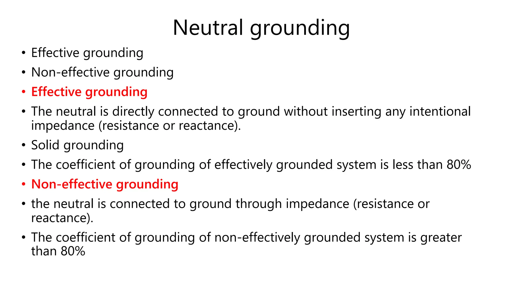
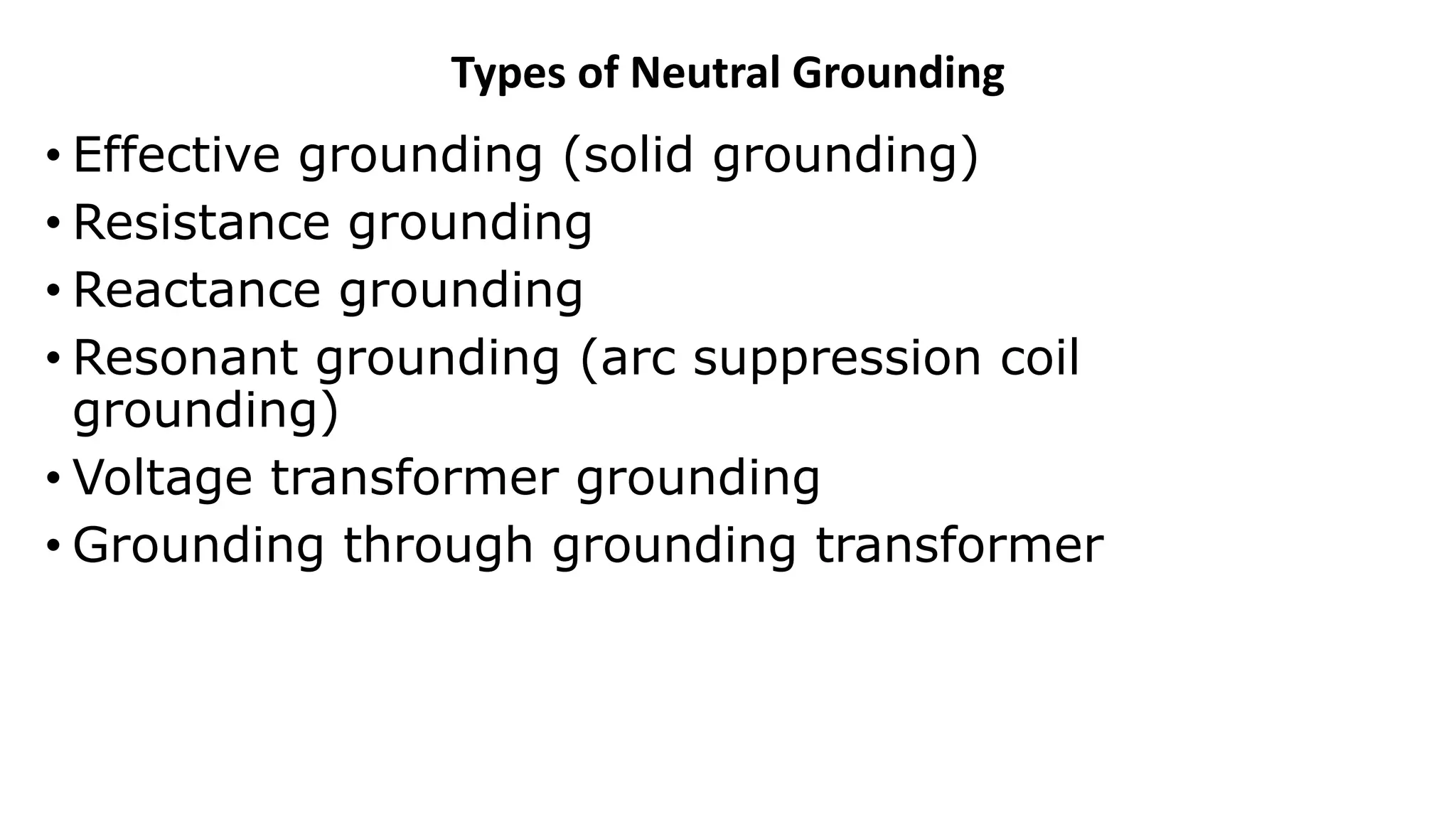
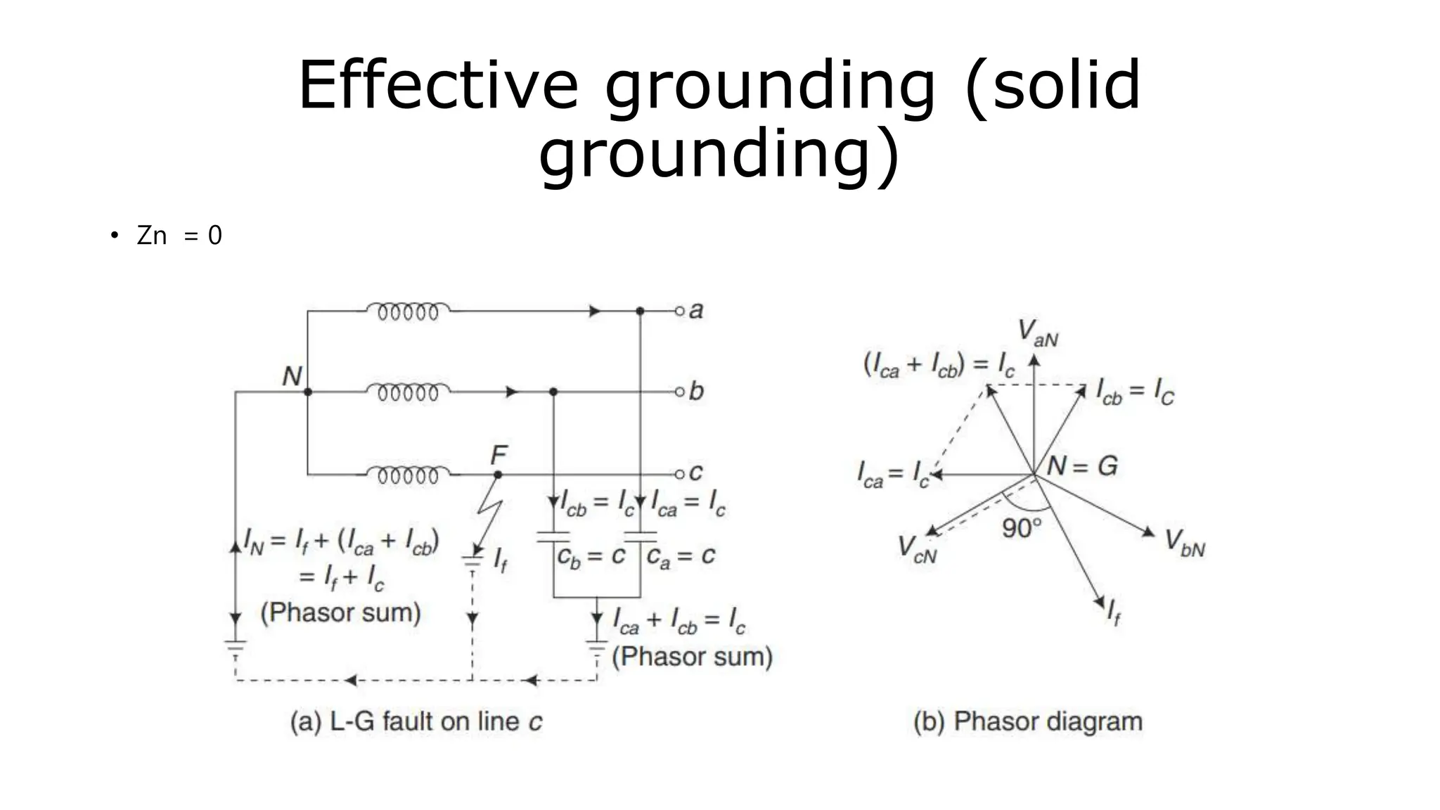
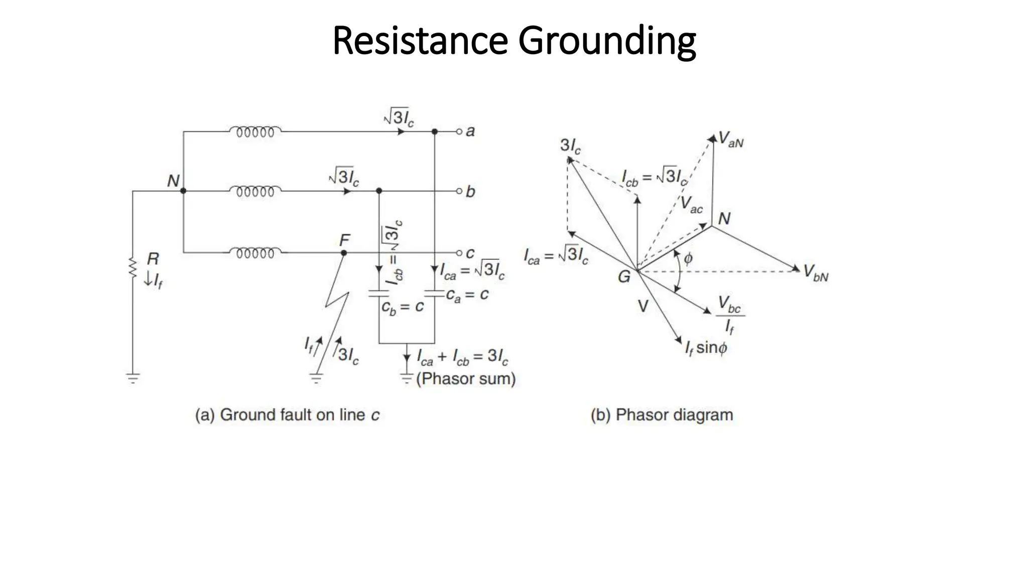
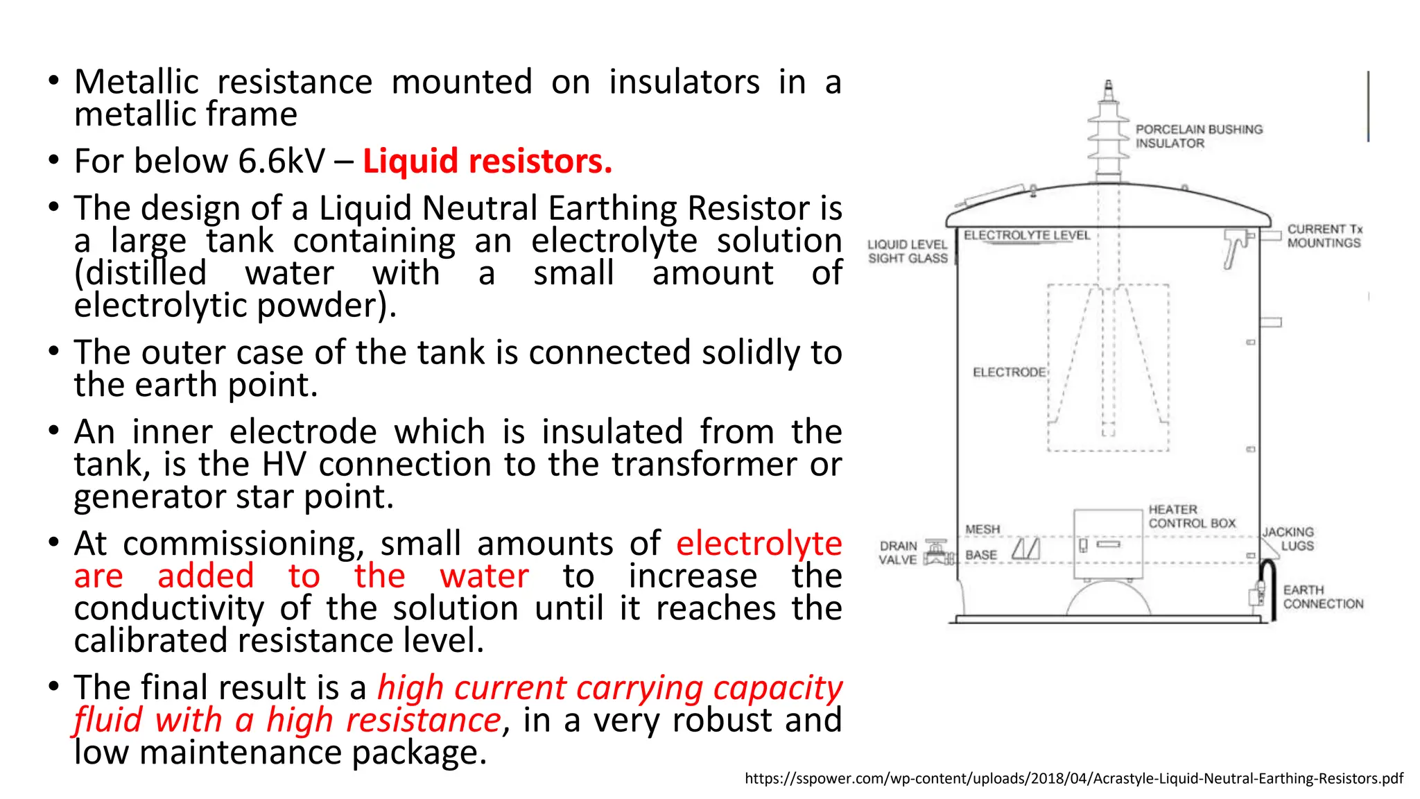
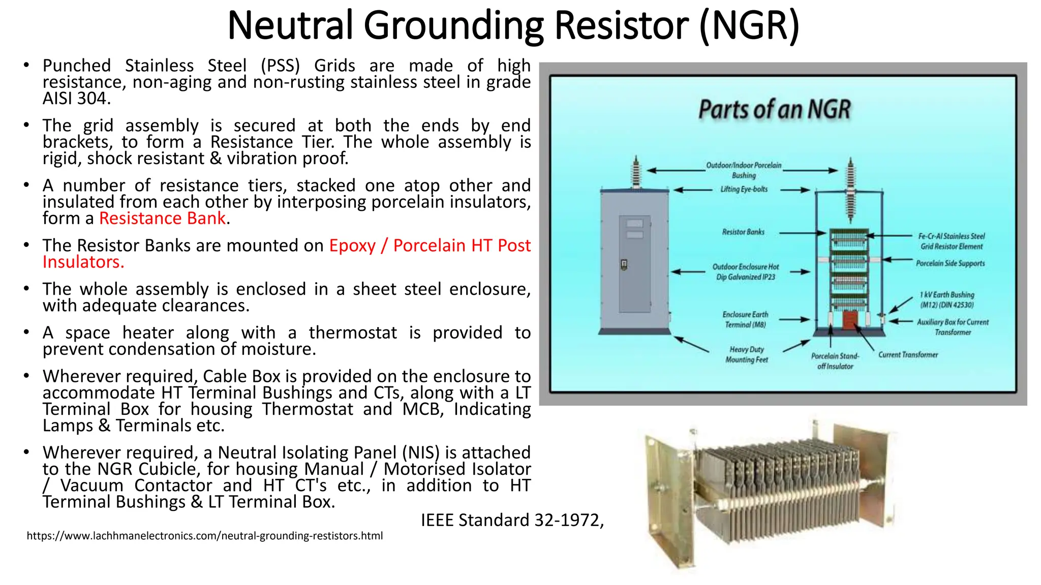
- There are three main types of neutral grounding: ungrounded, impedance-grounded using resistance or reactance, and effectively grounded by solid connection. Resistance grounding controls fault currents by inserting resistance.
- Grounding provides overvoltage protection, stabilizes the neutral point, allows for effective fault detection, increases insulation life, and improves safety and reliability.