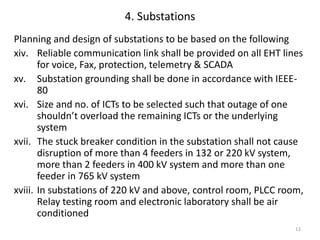
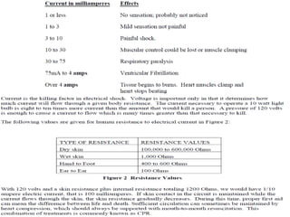
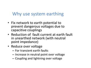
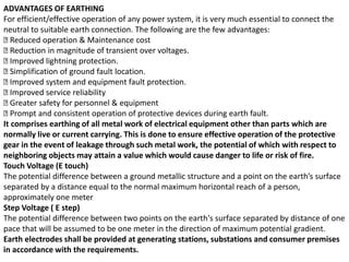
Download to read offline
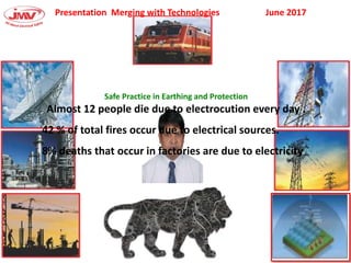
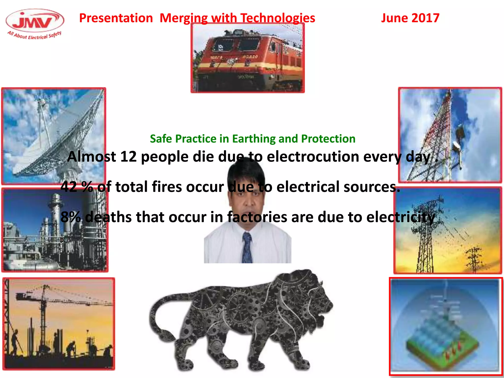
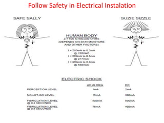
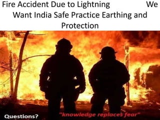
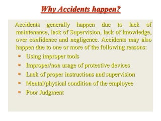
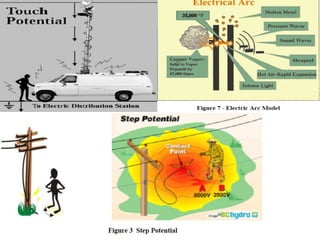
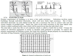
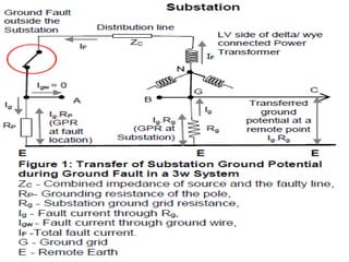


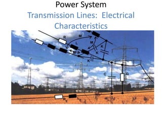


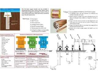
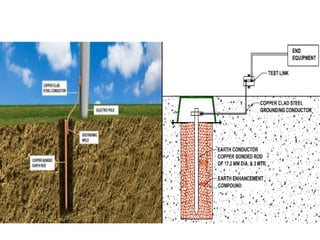


This document discusses safety practices regarding earthing and protection in electrical installations. It notes that approximately 12 people die every day and 42% of total fires occur due to electrical sources in India. Proper earthing and use of protective devices is important for safety. Factors like lack of maintenance, supervision, knowledge and negligence can lead to accidents. The document discusses causes of arcing faults and lightning accidents. It emphasizes the importance of proper earthing for safety, maintenance of voltage levels, and operation of protection devices. Earthing reduces touch and step voltages to safe levels.


