SlideShare a Scribd company logo
ferent modes/functions could be provided by this machine
1. Mill MODE
2. Lathe MODE
Mill Mode:
In Mill mode operation the work piece is in tool post and tool is in spindle and the work
piece can be moved in three directions (X, Y, Z).
Lathe Mode:
In lathe mode the work piece is in spindle and tool in tool post and there are eight
position for tool, four are for periphery and four are for axially.
In lathe mode the tool post can be moved only in X and Z direction
MACHINE CONTROLS:
3D CAD CAM centre is controlled by the help of different control buttons and programs.
Among them following are the most important;
1. Spindle control:
 Spindle forward
 Spindle reverse
 Spindle stop
2. Feed Speed Control:
It control the tool feed speeds in the X,Y,Z axes from 0 to 100% in 10% increments.
3. Jog axes control:
There are five buttons which controls manual movement of the table in the X and Z axes. These
buttons provide the rapid movement in the indicated direction.
4. Manual:
This button used for manual mode. When light ON the machine is operated by control panel and
when we press MAN button light goes turn OFF and machine operate by computer (automatic
mode).
5. Coolant:
This is used for controlling machine’s inner temperature.
6. Feed Hold:
It Acts as an interrupt control to the program and also preventing any further tool movement until
it canceled.
7. Single Block:
It is the automatic mode controlled from the pc when machine is running. This allows the
operation of only a single block (line) of the program at a time.
8. Cycle Start:
It sets the automatic model and starts the machining from the PC program.
9. Power ON/reset:
Power ON switch is used for machine start and reset is used for any trip out.
10. Turret index:
This is used for turret tool holder into the next tool position.
11. Emergency stop:
This button used for emergency purpose.
OPERATION:
 First a design is drawn using design software in the
Computer attached.
 Secondly this program is converted into the machine
codes.
 A command is given to the machine to process
according to the set of instructions.
 Feed rate and spindle speed is specified in the
program.
 The processes could be also accomplished by manual
operation.
 Manual operation needs a professional to be skilled
one
EXPERIMENT NO.3
Title: To Perform Turning Operation in Lathe
Mode
CONVERSION MODES: In order to perform the lathe operation, if the machine is
currently in the milling Mode then we need to convert the Mode of operation from
milling to lathe mode.
This involves the following steps;
 To clamps the tool post
 To insert the work piece in chuck that is rotated by the spindle revolution
Theoretical Background:
Turning:
Turning is a machining process in which a cutting tool removes material by
moving more or less linearly while the work piece rotates. The tool's axes of movement
may be literally a straight line, or they may be along some set of curves or angles, but
they are essentially linear.
Turning Types:
 Facing
 Contour turning
 Chamfering
 Cutoff
 Threading
Operational steps:
 First the conversion from mill to lathe mode is done
 Then a work piece of Teflon is clamped tightly in the
chuck
 The cutting tool is clampsed in the tool post
 A sketch for the taper turning is drawn in the software
 The machine is turned on
 The command is given to the machine to start the operation
EXPERIMENT NO.4
Title: To Perform Milling operation on CAD CAM CENTRE
CONVERSION MODES: In order to perform the milling operation, if the machine is
currently in the Lathe Mode then we need to convert the Mode of operation from Lathe to
Milling mode.
This involves the following steps;
 Removing the tool post and adding the Machine vice for holding the work
part.
 Inserting the tool in the chuck that is revolved by the spindle.
THEORATICAL BACKGROUND:
MILLING: Milling is a machining operation in which a work part is
fed past a rotating cylindrical tool with multiple cutting edges. The
axis of rotation of the cutting tool is perpendicular to the direction of
feed. The cutting tool in milling is called milling cutter and the
cutting edges are called teeth.
Milling types;
1. Peripheral milling
 Cutter axis is parallel to surface being machined
 Cutting edges on outside periphery of cutter
 It involves the following operations;
o Slab milling
o Slotting
o Side milling
o Straddle milling
2. Face milling
 Cutter axis is perpendicular to surface being milled
 Cutting edges on both the end and outside periphery of the cutter
 It involves the following operations;
o Conventional face milling
o Partial face milling
o End milling
o Profile milling
o Pocket milling
o Surface contouring
OPERATIONAL STEPS:
 First the conversion from lathe to mill
mode is done
 Then a work piece of Teflon is clamped
tightly on the table.
 The end mill cutter is fixed in the jaws of the chuck tightly.
 The safety door is closed and the machine is started.
 After that appropriate depth of cut is given visually.
 The depth is in z-direction.
 Then spindle is started and feed perpendicular to the axis of rotation is given to the work
piece i-e in x-direction.
 In this way face milling of the material is
performed.
AUTOMATIC OPERATION:
PROGRAM & SEQUENCING:
Cutting dia: 7.00mm
Feed: .05 mm/rev
Spindle speed: 10000 rpm
Target or reference point of tool;
x = 0, y = -50, z = +10
units = millimeter
Program:
NOO1 G21 G90 G92 X0 Y-50 Z10;
NOO2 G00 X70 Y30;
N003 G01 G95 Z-15 F.05 S1000 M03;
N004 G01 Z10.0;
N005 G00 Y60;
N006 G01 G95 Z-15 F 0.05;
N007 G01 Z10;
N008 G0 X120 Y30;
N009 G01 G95 Z-15 F 0.05;
N010 G01 Z10;
N011 G00 X0 Y-50 M05;
N012 M30;
(End of program and stop working)
EXPERIMENT NO.5
Title: Programming in CNC
TheoreticalBackground:
COMPUTER NUMERICALLY CONTROL (CNC):
ComputerNumerical Control isthe control of amachine tool usingnumbersandletters. It is a system in
whichprogrammed numerical values are directly inserted and stored on some form of input medium,
and automatically read and decoded to cause a corresponding movement in the machine which it is
controlling.
ADVANTAGES OF CNC:
 Reducedscrap.Errors due to operator fatigue, interruptions, and other factors are less
likely to occur.
 Simplifiedinspection.Once the firstpiece has passed inspection, minimal inspection is
required on subsequent parts
 Lower tooling costs due to less need for complex jigs and fixtures.
 Reduced lead time.
 Complex machiningoperationsare more easilyaccomplisheddue to advanced machine
control.
 High degree of quality due to accuracy, repeatability, and freedom from
DISADVANTAGES OF CNC:
 Tools on NC machines do not cut metal any faster than conventional machines.
 NC does not eliminate the need for expensive tools. There is also a greater initial cost
involved with the NC machine.
 NC will not totally eliminate errors. Operators can still fail to push the correct buttons,
make incorrect alignments, and fail to locate parts properly in a fixture.
 Selection and training of programmers and maintenance personnel is required.
Pre-requisites for CNC programming
1- Cutting Data and Formulas
Here are some of the most common terms used for expressing cutting data:
 Spindlespeed - Spindle speed is the rotational speed of the spindle and tooling. This value is
usually expressed in RPM. (Revolutions Per Minute)
 Feed rate value - The feedrate value isthe numerical value atwhicha tool will traverse a work
piece. It is usually expressed in either IPM(Inches Per Minute) or IPR (Inches Per Revolution).
 Cuttingspeed - Cuttingspeedisthe rotational speedof the cuttingtool or work piece. It can be
stated as either RPMor SFM. (Surface Feet Per Minute)
 Depth of Cut - Depth of cut is the distance the tool tip is engaged into the work piece. It is
incorporated into the X, Y, and Z values in a CNC program.
2- Blueprint Reading
Blueprintreadingisabasicskill inthe manufacturingindustrythatall engineers, managers, CNC
programmers,CNCoperator,machinists,andinspectorsshouldknow inmanufacturingindustry.
3- Operations Sheet:
The operations sheet, or setup sheet, is used to
describe the processes needed to machine a
part on a CNC machine. Each process is
written out in the proper machining sequence
and includes the tool to be used and all
cutting data. Programming the outer contour
is one operation in the machining of a part. To
accomplish this you must first have a part
origin. Then, the points required for
machining would be calculated for the center
of the tool to be used, offset the radius of the
tool, from the actual part edge coordinates.
Unit Systems and Input Modes
Unit Systems are the units of measurement to be used for the CNC program. All machines understand
both English and Metric standards. When programming in english units you are using inches. And in
metric its the millimeter (mm.). The CNC machine needs to be told which units are being used. Some
machinesare automatically set-up at the factory for inches or mm. normally at the beginning of a CNC
program you will see either; G70 to specify inches or G71 to specify mm.
Input modes refer to the type of coordinate information that is input into the program for the CNC
machine. There are two types.
 Absolute input,designatedbythe G90 code,specifiesdistancesfromthe originorprogram zero
point. Absolute is the most common mode.
 Incremental input,designatedbythe G91 code,specifiesdistancesand directions based on the
previouspointasan origin.Incremental inputissometimecalledpoint-to-point.All CNCsystems
can be switched from absolute to incremental mode and back unlimited times within a
program.
Other input modes such as Helical also exist.
Letter Code Descriptions
N Sequence Number
G PreparatoryFunctions
X X AxisCommand
Y Y AxisCommand
Z Z AxisCommand
R Radiusfromspecified center
A Angle CCWfrom+X vector
I X axisarc centeroffset
J Y axisarc centeroffset
K Z axisarc centeroffset
F Feedrate
S Spindle speed
T Tool number
M Miscellaneousfunction
Absolute
40,40
Current
positionof
tool
20, 20
20,20
Incremental
Nextpositionof tool

More Related Content

What's hot

What's hot (20)

Funuc progaming
Funuc progamingFunuc progaming
Funuc progaming
 
Cnc machine
Cnc machineCnc machine
Cnc machine
 
Cnc Milling
Cnc MillingCnc Milling
Cnc Milling
 
Cnc Milling (Heidenhain ISO)
Cnc Milling (Heidenhain ISO)Cnc Milling (Heidenhain ISO)
Cnc Milling (Heidenhain ISO)
 
Universal CNC Milling Machine
Universal CNC Milling MachineUniversal CNC Milling Machine
Universal CNC Milling Machine
 
G and m_programming_for_mills_manual
G and m_programming_for_mills_manualG and m_programming_for_mills_manual
G and m_programming_for_mills_manual
 
Interpolations
InterpolationsInterpolations
Interpolations
 
Cnc part programming 4 unit
Cnc part programming 4 unitCnc part programming 4 unit
Cnc part programming 4 unit
 
Cnc ppt by APC Sir
Cnc ppt by APC SirCnc ppt by APC Sir
Cnc ppt by APC Sir
 
Ncmachine (1)
Ncmachine (1)Ncmachine (1)
Ncmachine (1)
 
Cnc axis and motion nomenclature
Cnc axis and motion nomenclatureCnc axis and motion nomenclature
Cnc axis and motion nomenclature
 
4 basic cnc programming milling
4 basic cnc programming milling4 basic cnc programming milling
4 basic cnc programming milling
 
CNC
CNCCNC
CNC
 
CNC Lathe Operating & Programming
CNC Lathe Operating & ProgrammingCNC Lathe Operating & Programming
CNC Lathe Operating & Programming
 
CNC Programmingmodifies examination 1
CNC Programmingmodifies examination 1CNC Programmingmodifies examination 1
CNC Programmingmodifies examination 1
 
CNC MILLING
CNC MILLINGCNC MILLING
CNC MILLING
 
introduction to CNC machine.
introduction to CNC machine.introduction to CNC machine.
introduction to CNC machine.
 
CNC.pdf
CNC.pdfCNC.pdf
CNC.pdf
 
Portfolio - CNC Programming Project
Portfolio - CNC Programming ProjectPortfolio - CNC Programming Project
Portfolio - CNC Programming Project
 
Cnc turning
Cnc turning Cnc turning
Cnc turning
 

Similar to Production automation lab

Computer integrated Manufacture & design Lab Manual
Computer integrated Manufacture & design Lab  ManualComputer integrated Manufacture & design Lab  Manual
Computer integrated Manufacture & design Lab ManualSpikeAerotek
 
CAD CAM Exercise CNC PROGRAMMING LATHE.pptx
CAD CAM Exercise CNC PROGRAMMING LATHE.pptxCAD CAM Exercise CNC PROGRAMMING LATHE.pptx
CAD CAM Exercise CNC PROGRAMMING LATHE.pptxPraveen Kumar
 
CNC Maching.pptx
CNC Maching.pptxCNC Maching.pptx
CNC Maching.pptxstudyall1
 
CNC PART PROGRAMMING.pptx
CNC PART PROGRAMMING.pptxCNC PART PROGRAMMING.pptx
CNC PART PROGRAMMING.pptxAtharvaJagtap15
 
Numerical control and CNC
Numerical control and CNCNumerical control and CNC
Numerical control and CNCnmahi96
 
CNC part programming
CNC part programmingCNC part programming
CNC part programmingjntuhcej
 
CAD-CAM-Module-4-Subtractive-Manufacturing-1-print.pptx
CAD-CAM-Module-4-Subtractive-Manufacturing-1-print.pptxCAD-CAM-Module-4-Subtractive-Manufacturing-1-print.pptx
CAD-CAM-Module-4-Subtractive-Manufacturing-1-print.pptxsahils237192101
 
Cam presentation..
Cam presentation..Cam presentation..
Cam presentation..Akash Maurya
 
introduction to cnc machines
 introduction to cnc machines introduction to cnc machines
introduction to cnc machinesSTAY CURIOUS
 
internship presentation.pptx
internship presentation.pptxinternship presentation.pptx
internship presentation.pptxChinmaiKumar
 
Microproject on cnc milling machine
Microproject on cnc milling machineMicroproject on cnc milling machine
Microproject on cnc milling machineSumitSutar6
 
808D_OP_Milling_0113_en.pdf
808D_OP_Milling_0113_en.pdf808D_OP_Milling_0113_en.pdf
808D_OP_Milling_0113_en.pdfmanop machine
 

Similar to Production automation lab (20)

Computer integrated Manufacture & design Lab Manual
Computer integrated Manufacture & design Lab  ManualComputer integrated Manufacture & design Lab  Manual
Computer integrated Manufacture & design Lab Manual
 
CAD CAM Exercise CNC PROGRAMMING LATHE.pptx
CAD CAM Exercise CNC PROGRAMMING LATHE.pptxCAD CAM Exercise CNC PROGRAMMING LATHE.pptx
CAD CAM Exercise CNC PROGRAMMING LATHE.pptx
 
CNC Programmingmodifies1
CNC Programmingmodifies1CNC Programmingmodifies1
CNC Programmingmodifies1
 
CNC Maching.pptx
CNC Maching.pptxCNC Maching.pptx
CNC Maching.pptx
 
CNC PART PROGRAMMING.pptx
CNC PART PROGRAMMING.pptxCNC PART PROGRAMMING.pptx
CNC PART PROGRAMMING.pptx
 
Numerical control and CNC
Numerical control and CNCNumerical control and CNC
Numerical control and CNC
 
CNC part programming
CNC part programmingCNC part programming
CNC part programming
 
Cnc programming basics.doc
Cnc programming basics.docCnc programming basics.doc
Cnc programming basics.doc
 
CAD-CAM-Module-4-Subtractive-Manufacturing-1-print.pptx
CAD-CAM-Module-4-Subtractive-Manufacturing-1-print.pptxCAD-CAM-Module-4-Subtractive-Manufacturing-1-print.pptx
CAD-CAM-Module-4-Subtractive-Manufacturing-1-print.pptx
 
part programming (cnc)
part programming (cnc)part programming (cnc)
part programming (cnc)
 
Cam presentation..
Cam presentation..Cam presentation..
Cam presentation..
 
introduction to cnc machines
 introduction to cnc machines introduction to cnc machines
introduction to cnc machines
 
9.pmat m 01
9.pmat m 019.pmat m 01
9.pmat m 01
 
internship presentation.pptx
internship presentation.pptxinternship presentation.pptx
internship presentation.pptx
 
Cnc programming
Cnc programmingCnc programming
Cnc programming
 
Cnc programming
Cnc programmingCnc programming
Cnc programming
 
Cncprogramming
CncprogrammingCncprogramming
Cncprogramming
 
Microproject on cnc milling machine
Microproject on cnc milling machineMicroproject on cnc milling machine
Microproject on cnc milling machine
 
808D_OP_Milling_0113_en.pdf
808D_OP_Milling_0113_en.pdf808D_OP_Milling_0113_en.pdf
808D_OP_Milling_0113_en.pdf
 
CNC Milling
CNC MillingCNC Milling
CNC Milling
 

More from ismail khan

Mini project groups (1)
Mini project groups (1)Mini project groups (1)
Mini project groups (1)ismail khan
 
How to write cv, sop and email to professor
How to write cv, sop and email to professorHow to write cv, sop and email to professor
How to write cv, sop and email to professorismail khan
 

More from ismail khan (6)

Mini project groups (1)
Mini project groups (1)Mini project groups (1)
Mini project groups (1)
 
Group names
Group namesGroup names
Group names
 
Bulldozer
BulldozerBulldozer
Bulldozer
 
C++ 1
C++  1C++  1
C++ 1
 
Pso form
Pso form Pso form
Pso form
 
How to write cv, sop and email to professor
How to write cv, sop and email to professorHow to write cv, sop and email to professor
How to write cv, sop and email to professor
 

Recently uploaded

Explosives Industry manufacturing process.pdf
Explosives Industry manufacturing process.pdfExplosives Industry manufacturing process.pdf
Explosives Industry manufacturing process.pdf884710SadaqatAli
 
shape functions of 1D and 2 D rectangular elements.pptx
shape functions of 1D and 2 D rectangular elements.pptxshape functions of 1D and 2 D rectangular elements.pptx
shape functions of 1D and 2 D rectangular elements.pptxVishalDeshpande27
 
Automobile Management System Project Report.pdf
Automobile Management System Project Report.pdfAutomobile Management System Project Report.pdf
Automobile Management System Project Report.pdfKamal Acharya
 
Halogenation process of chemical process industries
Halogenation process of chemical process industriesHalogenation process of chemical process industries
Halogenation process of chemical process industriesMuhammadTufail242431
 
KIT-601 Lecture Notes-UNIT-3.pdf Mining Data Stream
KIT-601 Lecture Notes-UNIT-3.pdf Mining Data StreamKIT-601 Lecture Notes-UNIT-3.pdf Mining Data Stream
KIT-601 Lecture Notes-UNIT-3.pdf Mining Data StreamDr. Radhey Shyam
 
A CASE STUDY ON ONLINE TICKET BOOKING SYSTEM PROJECT.pdf
A CASE STUDY ON ONLINE TICKET BOOKING SYSTEM PROJECT.pdfA CASE STUDY ON ONLINE TICKET BOOKING SYSTEM PROJECT.pdf
A CASE STUDY ON ONLINE TICKET BOOKING SYSTEM PROJECT.pdfKamal Acharya
 
Construction method of steel structure space frame .pptx
Construction method of steel structure space frame .pptxConstruction method of steel structure space frame .pptx
Construction method of steel structure space frame .pptxwendy cai
 
Introduction to Machine Learning Unit-4 Notes for II-II Mechanical Engineering
Introduction to Machine Learning Unit-4 Notes for II-II Mechanical EngineeringIntroduction to Machine Learning Unit-4 Notes for II-II Mechanical Engineering
Introduction to Machine Learning Unit-4 Notes for II-II Mechanical EngineeringC Sai Kiran
 
CFD Simulation of By-pass Flow in a HRSG module by R&R Consult.pptx
CFD Simulation of By-pass Flow in a HRSG module by R&R Consult.pptxCFD Simulation of By-pass Flow in a HRSG module by R&R Consult.pptx
CFD Simulation of By-pass Flow in a HRSG module by R&R Consult.pptxR&R Consult
 
Laundry management system project report.pdf
Laundry management system project report.pdfLaundry management system project report.pdf
Laundry management system project report.pdfKamal Acharya
 
retail automation billing system ppt.pptx
retail automation billing system ppt.pptxretail automation billing system ppt.pptx
retail automation billing system ppt.pptxfaamieahmd
 
RS Khurmi Machine Design Clutch and Brake Exercise Numerical Solutions
RS Khurmi Machine Design Clutch and Brake Exercise Numerical SolutionsRS Khurmi Machine Design Clutch and Brake Exercise Numerical Solutions
RS Khurmi Machine Design Clutch and Brake Exercise Numerical SolutionsAtif Razi
 
Hall booking system project report .pdf
Hall booking system project report  .pdfHall booking system project report  .pdf
Hall booking system project report .pdfKamal Acharya
 
Furniture showroom management system project.pdf
Furniture showroom management system project.pdfFurniture showroom management system project.pdf
Furniture showroom management system project.pdfKamal Acharya
 
KIT-601 Lecture Notes-UNIT-4.pdf Frequent Itemsets and Clustering
KIT-601 Lecture Notes-UNIT-4.pdf Frequent Itemsets and ClusteringKIT-601 Lecture Notes-UNIT-4.pdf Frequent Itemsets and Clustering
KIT-601 Lecture Notes-UNIT-4.pdf Frequent Itemsets and ClusteringDr. Radhey Shyam
 
AI for workflow automation Use cases applications benefits and development.pdf
AI for workflow automation Use cases applications benefits and development.pdfAI for workflow automation Use cases applications benefits and development.pdf
AI for workflow automation Use cases applications benefits and development.pdfmahaffeycheryld
 
ENERGY STORAGE DEVICES INTRODUCTION UNIT-I
ENERGY STORAGE DEVICES  INTRODUCTION UNIT-IENERGY STORAGE DEVICES  INTRODUCTION UNIT-I
ENERGY STORAGE DEVICES INTRODUCTION UNIT-IVigneshvaranMech
 
İTÜ CAD and Reverse Engineering Workshop
İTÜ CAD and Reverse Engineering WorkshopİTÜ CAD and Reverse Engineering Workshop
İTÜ CAD and Reverse Engineering WorkshopEmre Günaydın
 
Online resume builder management system project report.pdf
Online resume builder management system project report.pdfOnline resume builder management system project report.pdf
Online resume builder management system project report.pdfKamal Acharya
 
ONLINE VEHICLE RENTAL SYSTEM PROJECT REPORT.pdf
ONLINE VEHICLE RENTAL SYSTEM PROJECT REPORT.pdfONLINE VEHICLE RENTAL SYSTEM PROJECT REPORT.pdf
ONLINE VEHICLE RENTAL SYSTEM PROJECT REPORT.pdfKamal Acharya
 

Recently uploaded (20)

Explosives Industry manufacturing process.pdf
Explosives Industry manufacturing process.pdfExplosives Industry manufacturing process.pdf
Explosives Industry manufacturing process.pdf
 
shape functions of 1D and 2 D rectangular elements.pptx
shape functions of 1D and 2 D rectangular elements.pptxshape functions of 1D and 2 D rectangular elements.pptx
shape functions of 1D and 2 D rectangular elements.pptx
 
Automobile Management System Project Report.pdf
Automobile Management System Project Report.pdfAutomobile Management System Project Report.pdf
Automobile Management System Project Report.pdf
 
Halogenation process of chemical process industries
Halogenation process of chemical process industriesHalogenation process of chemical process industries
Halogenation process of chemical process industries
 
KIT-601 Lecture Notes-UNIT-3.pdf Mining Data Stream
KIT-601 Lecture Notes-UNIT-3.pdf Mining Data StreamKIT-601 Lecture Notes-UNIT-3.pdf Mining Data Stream
KIT-601 Lecture Notes-UNIT-3.pdf Mining Data Stream
 
A CASE STUDY ON ONLINE TICKET BOOKING SYSTEM PROJECT.pdf
A CASE STUDY ON ONLINE TICKET BOOKING SYSTEM PROJECT.pdfA CASE STUDY ON ONLINE TICKET BOOKING SYSTEM PROJECT.pdf
A CASE STUDY ON ONLINE TICKET BOOKING SYSTEM PROJECT.pdf
 
Construction method of steel structure space frame .pptx
Construction method of steel structure space frame .pptxConstruction method of steel structure space frame .pptx
Construction method of steel structure space frame .pptx
 
Introduction to Machine Learning Unit-4 Notes for II-II Mechanical Engineering
Introduction to Machine Learning Unit-4 Notes for II-II Mechanical EngineeringIntroduction to Machine Learning Unit-4 Notes for II-II Mechanical Engineering
Introduction to Machine Learning Unit-4 Notes for II-II Mechanical Engineering
 
CFD Simulation of By-pass Flow in a HRSG module by R&R Consult.pptx
CFD Simulation of By-pass Flow in a HRSG module by R&R Consult.pptxCFD Simulation of By-pass Flow in a HRSG module by R&R Consult.pptx
CFD Simulation of By-pass Flow in a HRSG module by R&R Consult.pptx
 
Laundry management system project report.pdf
Laundry management system project report.pdfLaundry management system project report.pdf
Laundry management system project report.pdf
 
retail automation billing system ppt.pptx
retail automation billing system ppt.pptxretail automation billing system ppt.pptx
retail automation billing system ppt.pptx
 
RS Khurmi Machine Design Clutch and Brake Exercise Numerical Solutions
RS Khurmi Machine Design Clutch and Brake Exercise Numerical SolutionsRS Khurmi Machine Design Clutch and Brake Exercise Numerical Solutions
RS Khurmi Machine Design Clutch and Brake Exercise Numerical Solutions
 
Hall booking system project report .pdf
Hall booking system project report  .pdfHall booking system project report  .pdf
Hall booking system project report .pdf
 
Furniture showroom management system project.pdf
Furniture showroom management system project.pdfFurniture showroom management system project.pdf
Furniture showroom management system project.pdf
 
KIT-601 Lecture Notes-UNIT-4.pdf Frequent Itemsets and Clustering
KIT-601 Lecture Notes-UNIT-4.pdf Frequent Itemsets and ClusteringKIT-601 Lecture Notes-UNIT-4.pdf Frequent Itemsets and Clustering
KIT-601 Lecture Notes-UNIT-4.pdf Frequent Itemsets and Clustering
 
AI for workflow automation Use cases applications benefits and development.pdf
AI for workflow automation Use cases applications benefits and development.pdfAI for workflow automation Use cases applications benefits and development.pdf
AI for workflow automation Use cases applications benefits and development.pdf
 
ENERGY STORAGE DEVICES INTRODUCTION UNIT-I
ENERGY STORAGE DEVICES  INTRODUCTION UNIT-IENERGY STORAGE DEVICES  INTRODUCTION UNIT-I
ENERGY STORAGE DEVICES INTRODUCTION UNIT-I
 
İTÜ CAD and Reverse Engineering Workshop
İTÜ CAD and Reverse Engineering WorkshopİTÜ CAD and Reverse Engineering Workshop
İTÜ CAD and Reverse Engineering Workshop
 
Online resume builder management system project report.pdf
Online resume builder management system project report.pdfOnline resume builder management system project report.pdf
Online resume builder management system project report.pdf
 
ONLINE VEHICLE RENTAL SYSTEM PROJECT REPORT.pdf
ONLINE VEHICLE RENTAL SYSTEM PROJECT REPORT.pdfONLINE VEHICLE RENTAL SYSTEM PROJECT REPORT.pdf
ONLINE VEHICLE RENTAL SYSTEM PROJECT REPORT.pdf
 

Production automation lab

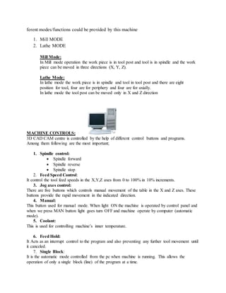
  • 1. ferent modes/functions could be provided by this machine 1. Mill MODE 2. Lathe MODE Mill Mode: In Mill mode operation the work piece is in tool post and tool is in spindle and the work piece can be moved in three directions (X, Y, Z). Lathe Mode: In lathe mode the work piece is in spindle and tool in tool post and there are eight position for tool, four are for periphery and four are for axially. In lathe mode the tool post can be moved only in X and Z direction MACHINE CONTROLS: 3D CAD CAM centre is controlled by the help of different control buttons and programs. Among them following are the most important; 1. Spindle control:  Spindle forward  Spindle reverse  Spindle stop 2. Feed Speed Control: It control the tool feed speeds in the X,Y,Z axes from 0 to 100% in 10% increments. 3. Jog axes control: There are five buttons which controls manual movement of the table in the X and Z axes. These buttons provide the rapid movement in the indicated direction. 4. Manual: This button used for manual mode. When light ON the machine is operated by control panel and when we press MAN button light goes turn OFF and machine operate by computer (automatic mode). 5. Coolant: This is used for controlling machine’s inner temperature. 6. Feed Hold: It Acts as an interrupt control to the program and also preventing any further tool movement until it canceled. 7. Single Block: It is the automatic mode controlled from the pc when machine is running. This allows the operation of only a single block (line) of the program at a time.
  • 2. 8. Cycle Start: It sets the automatic model and starts the machining from the PC program. 9. Power ON/reset: Power ON switch is used for machine start and reset is used for any trip out. 10. Turret index: This is used for turret tool holder into the next tool position. 11. Emergency stop: This button used for emergency purpose. OPERATION:  First a design is drawn using design software in the Computer attached.  Secondly this program is converted into the machine codes.  A command is given to the machine to process according to the set of instructions.  Feed rate and spindle speed is specified in the program.  The processes could be also accomplished by manual operation.  Manual operation needs a professional to be skilled one EXPERIMENT NO.3 Title: To Perform Turning Operation in Lathe Mode CONVERSION MODES: In order to perform the lathe operation, if the machine is currently in the milling Mode then we need to convert the Mode of operation from milling to lathe mode. This involves the following steps;  To clamps the tool post  To insert the work piece in chuck that is rotated by the spindle revolution Theoretical Background: Turning: Turning is a machining process in which a cutting tool removes material by moving more or less linearly while the work piece rotates. The tool's axes of movement
  • 3. may be literally a straight line, or they may be along some set of curves or angles, but they are essentially linear. Turning Types:  Facing  Contour turning  Chamfering  Cutoff  Threading Operational steps:  First the conversion from mill to lathe mode is done  Then a work piece of Teflon is clamped tightly in the chuck  The cutting tool is clampsed in the tool post  A sketch for the taper turning is drawn in the software  The machine is turned on  The command is given to the machine to start the operation EXPERIMENT NO.4 Title: To Perform Milling operation on CAD CAM CENTRE CONVERSION MODES: In order to perform the milling operation, if the machine is currently in the Lathe Mode then we need to convert the Mode of operation from Lathe to Milling mode. This involves the following steps;  Removing the tool post and adding the Machine vice for holding the work part.  Inserting the tool in the chuck that is revolved by the spindle. THEORATICAL BACKGROUND: MILLING: Milling is a machining operation in which a work part is fed past a rotating cylindrical tool with multiple cutting edges. The axis of rotation of the cutting tool is perpendicular to the direction of feed. The cutting tool in milling is called milling cutter and the cutting edges are called teeth.
  • 4. Milling types; 1. Peripheral milling  Cutter axis is parallel to surface being machined  Cutting edges on outside periphery of cutter  It involves the following operations; o Slab milling o Slotting o Side milling o Straddle milling 2. Face milling  Cutter axis is perpendicular to surface being milled  Cutting edges on both the end and outside periphery of the cutter  It involves the following operations; o Conventional face milling o Partial face milling o End milling o Profile milling o Pocket milling o Surface contouring OPERATIONAL STEPS:  First the conversion from lathe to mill mode is done  Then a work piece of Teflon is clamped tightly on the table.  The end mill cutter is fixed in the jaws of the chuck tightly.  The safety door is closed and the machine is started.  After that appropriate depth of cut is given visually.  The depth is in z-direction.  Then spindle is started and feed perpendicular to the axis of rotation is given to the work piece i-e in x-direction.  In this way face milling of the material is performed. AUTOMATIC OPERATION: PROGRAM & SEQUENCING: Cutting dia: 7.00mm
  • 5. Feed: .05 mm/rev Spindle speed: 10000 rpm Target or reference point of tool; x = 0, y = -50, z = +10 units = millimeter Program: NOO1 G21 G90 G92 X0 Y-50 Z10; NOO2 G00 X70 Y30; N003 G01 G95 Z-15 F.05 S1000 M03; N004 G01 Z10.0; N005 G00 Y60; N006 G01 G95 Z-15 F 0.05; N007 G01 Z10; N008 G0 X120 Y30; N009 G01 G95 Z-15 F 0.05; N010 G01 Z10; N011 G00 X0 Y-50 M05; N012 M30; (End of program and stop working) EXPERIMENT NO.5 Title: Programming in CNC TheoreticalBackground: COMPUTER NUMERICALLY CONTROL (CNC): ComputerNumerical Control isthe control of amachine tool usingnumbersandletters. It is a system in whichprogrammed numerical values are directly inserted and stored on some form of input medium, and automatically read and decoded to cause a corresponding movement in the machine which it is controlling. ADVANTAGES OF CNC:
  • 6.  Reducedscrap.Errors due to operator fatigue, interruptions, and other factors are less likely to occur.  Simplifiedinspection.Once the firstpiece has passed inspection, minimal inspection is required on subsequent parts  Lower tooling costs due to less need for complex jigs and fixtures.  Reduced lead time.  Complex machiningoperationsare more easilyaccomplisheddue to advanced machine control.  High degree of quality due to accuracy, repeatability, and freedom from DISADVANTAGES OF CNC:  Tools on NC machines do not cut metal any faster than conventional machines.  NC does not eliminate the need for expensive tools. There is also a greater initial cost involved with the NC machine.  NC will not totally eliminate errors. Operators can still fail to push the correct buttons, make incorrect alignments, and fail to locate parts properly in a fixture.  Selection and training of programmers and maintenance personnel is required. Pre-requisites for CNC programming 1- Cutting Data and Formulas Here are some of the most common terms used for expressing cutting data:  Spindlespeed - Spindle speed is the rotational speed of the spindle and tooling. This value is usually expressed in RPM. (Revolutions Per Minute)  Feed rate value - The feedrate value isthe numerical value atwhicha tool will traverse a work piece. It is usually expressed in either IPM(Inches Per Minute) or IPR (Inches Per Revolution).  Cuttingspeed - Cuttingspeedisthe rotational speedof the cuttingtool or work piece. It can be stated as either RPMor SFM. (Surface Feet Per Minute)  Depth of Cut - Depth of cut is the distance the tool tip is engaged into the work piece. It is incorporated into the X, Y, and Z values in a CNC program. 2- Blueprint Reading Blueprintreadingisabasicskill inthe manufacturingindustrythatall engineers, managers, CNC programmers,CNCoperator,machinists,andinspectorsshouldknow inmanufacturingindustry.
  • 7. 3- Operations Sheet: The operations sheet, or setup sheet, is used to describe the processes needed to machine a part on a CNC machine. Each process is written out in the proper machining sequence and includes the tool to be used and all cutting data. Programming the outer contour is one operation in the machining of a part. To accomplish this you must first have a part origin. Then, the points required for machining would be calculated for the center of the tool to be used, offset the radius of the tool, from the actual part edge coordinates. Unit Systems and Input Modes Unit Systems are the units of measurement to be used for the CNC program. All machines understand both English and Metric standards. When programming in english units you are using inches. And in metric its the millimeter (mm.). The CNC machine needs to be told which units are being used. Some machinesare automatically set-up at the factory for inches or mm. normally at the beginning of a CNC program you will see either; G70 to specify inches or G71 to specify mm. Input modes refer to the type of coordinate information that is input into the program for the CNC machine. There are two types.  Absolute input,designatedbythe G90 code,specifiesdistancesfromthe originorprogram zero point. Absolute is the most common mode.
  • 8.  Incremental input,designatedbythe G91 code,specifiesdistancesand directions based on the previouspointasan origin.Incremental inputissometimecalledpoint-to-point.All CNCsystems can be switched from absolute to incremental mode and back unlimited times within a program. Other input modes such as Helical also exist. Letter Code Descriptions N Sequence Number G PreparatoryFunctions X X AxisCommand Y Y AxisCommand Z Z AxisCommand R Radiusfromspecified center A Angle CCWfrom+X vector I X axisarc centeroffset J Y axisarc centeroffset K Z axisarc centeroffset F Feedrate S Spindle speed T Tool number M Miscellaneousfunction Absolute 40,40 Current positionof tool 20, 20 20,20 Incremental Nextpositionof tool