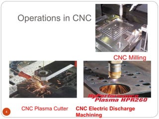
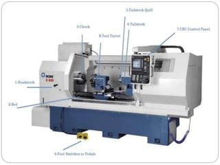
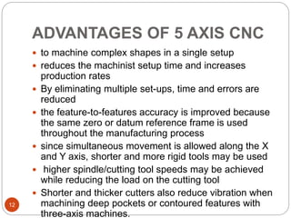
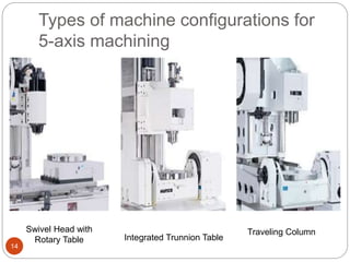
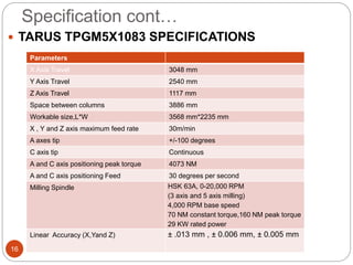
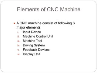
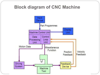
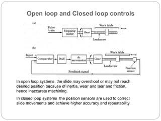
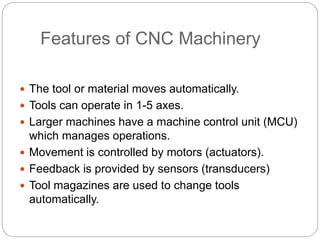
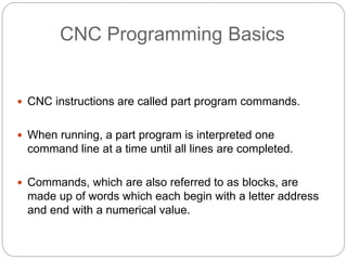
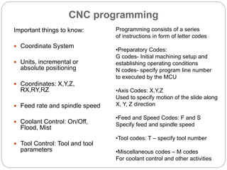
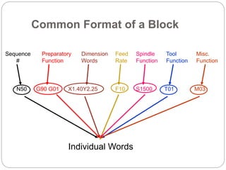
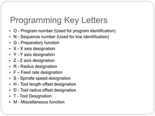
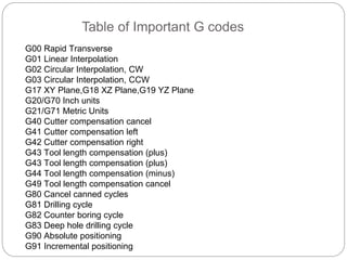
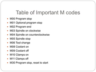
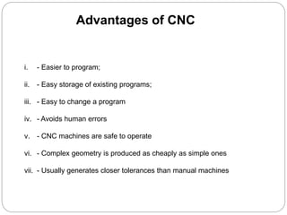
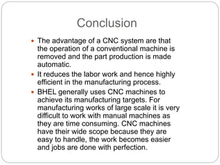
1. Introduction to CNC machines
 CO:- Develop part program for CNC Turning,
Milling and verify on simulation software.
Visit for more Learning Resources
Contents
2
• Introduction to CNC
• Operations in CNC
• Advantages and Disadvantages of CNC
• Axis selection
• 5 Axis CNC
• Advantages and application of 5 axis
• Types of machine configurations for 5-axis
machining
• Specification of a 5 axis CNC machine
Introduction to CNC
3
 Numerical control (NC) is the automation of
machine tools that are operated by precisely
programmed commands encoded on a storage
medium, as opposed to controlled manually.
 Most NC today is computer numerical control
(CNC), in which computers play an integral part of
the control.
 In modern CNC systems, end-to-end component
design is highly automated using computer-aided
design (CAD) and computer-aided manufacturing
(CAM) programs.
Operations in CNC
4
CNC Milling
CNC Plasma Cutter CNC Electric Discharge
Machining
6
 Other CNC Operations are:-
 CNC Water Jet Cutter
 Drilling
 Sheet metal works (Turret punch)
 Wire bending machines
 Surface grinders
 Cylindrical grinders
 submerged welding
 Glass cutting
Advantages of CNC
7
 CNC machines can be used continuously
 Batch production with high accuracy
 can be updated by improving the software
 Training in the use of CNCs is available through
the use of ‘virtual software’.
 Intricate detail machining
 no need to make a prototype or a model
 One person can supervise many CNC machines
simultaneously
 saves time
Disadvantages
8
 more expensive than manually operated
machines
 The CNC machine operator only needs basic
training and skills, enough to supervise several
machines. In years gone by, engineers needed
years of training to operate centre lathes, milling
machines and other manually operated
machines. This means many of the old skills are
been lost.
 Investment in CNC machines can lead to
Axes of CNC Machine Tool
9
From 3-axis to 5-axis machining
10
• not sufficient for the complete
finishing process for very
deep part and having narrow
cavities
• results in a bad surface
quality and long machining
times in Case of harder
material
• dozens of views need to be defined
• more tool movements
• programming is quite difficult
• sum of all views does not cover the
whole geometry
• overlapping views lead to surface
quality problems
• More number of lead-in and out
movements
Five Axis CNC
11
ADVANTAGES OF 5 AXIS CNC
12
 to machine complex shapes in a single setup
 reduces the machinist setup time and increases
production rates
 By eliminating multiple set-ups, time and errors are
reduced
 the feature-to-features accuracy is improved because
the same zero or datum reference frame is used
throughout the manufacturing process
 since simultaneous movement is allowed along the X
and Y axis, shorter and more rigid tools may be used
 higher spindle/cutting tool speeds may be achieved
while reducing the load on the cutting tool
 Shorter and thicker cutters also reduce vibration when
machining deep pockets or contoured features with
three-axis machines.
Application
13
 complex three dimensional profiles
 for impellers, turbine blades, and plastic mold
tools
Types of machine configurations for
5-axis machining
14
Swivel Head with
Rotary Table Integrated Trunnion Table
Traveling Column
Specification of a 5 axis CNC
Machine
15
 Manufacturers
HURCO
TARUS
CMS north America
OKUMA
CNC TAKANG Taiwan
maximart corporation
YCM (YEONG CHIN MACHINERY INDUSTRIES CO., LTD )
Specification cont…
16
 TARUS TPGM5X1083 SPECIFICATIONS
Parameters
X Axis Travel 3048 mm
Y Axis Travel 2540 mm
Z Axis Travel 1117 mm
Space between columns 3886 mm
Workable size,L*W 3568 mm*2235 mm
X , Y and Z axis maximum feed rate 30m/min
A axes tip +/-100 degrees
C axis tip Continuous
A and C axis positioning peak torque 4073 NM
A and C axis positioning Feed 30 degrees per second
Milling Spindle HSK 63A, 0-20,000 RPM
(3 axis and 5 axis milling)
4,000 RPM base speed
70 NM constant torque,160 NM peak torque
29 KW rated power
Linear Accuracy (X,Yand Z) ± .013 mm , ± 0.006 mm, ± 0.005 mm
CONTENTS
1. History
2. CNC Introduction
3. how they look like?
4. Elements of CNC
5. Block diagram of CNC
6. How CNC Works?
7. Features of CNC Machines
8. CNC Programming Basics
9. Common Format of a Block
10. Programming Key Letters
11. Table of important G-codes
12. Table of important M-codes
13. Advantages
14. Challenges
15. Conclusion
16. References
History
 The first NC machines were built in the
1940s and 1950s by Prof. John T
Parson.
 CNC machine came into existence after
evolution of computer around 1980.
 Modern CNC Machine are improving
further as the technology is changing
with a variety of functions according to
applications.
CNC Introduction
A numerical control
system in which the
data handling, control
sequences, and
response to input is
determined by an on-
board computer
system at the machine
tool.
CNC Machines- How do they look like?
Slides
Controller
Servo Motors
Display Console
Controller
Automated
Tool changer
Coolant
control
Chip collection and
removal
Elements of CNC Machine
 A CNC machine consist of following 6
major elements:
i. Input Device
ii. Machine Control Unit
iii. Machine Tool
iv. Driving System
v. Feedback Devices
vi. Display Unit
Block diagram of CNC Machine
Open loop and Closed loop controls
In open loop systems the slide may overshoot or may not reach
desired position because of inertia, wear and tear and friction,
hence inaccurate machining.
In closed loop systems the position sensors are used to correct
slide movements and achieve higher accuracy and repeatability
How CNC Works
 Controlled by G and M codes.
 These are number values and co-ordinates.
 Each number or code is assigned to a particular
operation.
 Typed in manually to CAD by machine operators.
 G & M codes are automatically generated by the
computer software.
Features of CNC Machinery
 The tool or material moves automatically.
 Tools can operate in 1-5 axes.
 Larger machines have a machine control unit (MCU)
which manages operations.
 Movement is controlled by motors (actuators).
 Feedback is provided by sensors (transducers)
 Tool magazines are used to change tools
automatically.
CNC Programming Basics
 CNC instructions are called part program commands.
 When running, a part program is interpreted one
command line at a time until all lines are completed.
 Commands, which are also referred to as blocks, are
made up of words which each begin with a letter address
and end with a numerical value.
CNC programming
Important things to know:
 Coordinate System
 Units, incremental or
absolute positioning
 Coordinates: X,Y,Z,
RX,RY,RZ
 Feed rate and spindle speed
 Coolant Control: On/Off,
Flood, Mist
 Tool Control: Tool and tool
parameters
Programming consists of a series
of instructions in form of letter codes
•Preparatory Codes:
G codes- Initial machining setup and
establishing operating conditions
N codes- specify program line number
to executed by the MCU
•Axis Codes: X,Y,Z
Used to specify motion of the slide along
X, Y, Z direction
•Feed and Speed Codes: F and S
Specify feed and spindle speed
•Tool codes: T – specify tool number
•Miscellaneous codes – M codes
For coolant control and other activities
Common Format of a Block
Sequence
#
Preparatory
Function
Dimension
Words
Feed
Rate
Spindle
Function
Tool
Function
Misc.
Function
N50 G90 G01 X1.40Y2.25 F10 S1500 T01 M03
Individual Words
Programming Key Letters
 O - Program number (Used for program identification)
 N - Sequence number (Used for line identification)
 G - Preparatory function
 X - X axis designation
 Y - Y axis designation
 Z - Z axis designation
 R - Radius designation
 F – Feed rate designation
 S - Spindle speed designation
 H - Tool length offset designation
 D - Tool radius offset designation
 T - Tool Designation
 M - Miscellaneous function
Table of Important G codes
G00 Rapid Transverse
G01 Linear Interpolation
G02 Circular Interpolation, CW
G03 Circular Interpolation, CCW
G17 XY Plane,G18 XZ Plane,G19 YZ Plane
G20/G70 Inch units
G21/G71 Metric Units
G40 Cutter compensation cancel
G41 Cutter compensation left
G42 Cutter compensation right
G43 Tool length compensation (plus)
G44 Tool length compensation (minus)
G49 Tool length compensation cancel
G80 Cancel canned cycles
G81 Drilling cycle
G82 Counter boring cycle
G83 Deep hole drilling cycle
G90 Absolute positioning
G91 Incremental positioning
Table of Important M codes
 M00 Program stop
 M01 Optional program stop
 M02 Program end
 M03 Spindle on clockwise
 M04 Spindle on counterclockwise
 M05 Spindle stop
 M06 Tool change
 M08 Coolant on
 M09 Coolant off
 M10 Clamps on
 M11 Clamps off
 M30 Program stop, reset to start
Advantages of CNC
i. - Easier to program;
ii. - Easy storage of existing programs;
iii. - Easy to change a program
iv. - Avoids human errors
v. - CNC machines are safe to operate
vi. - Complex geometry is produced as cheaply as simple ones
vii. - Usually generates closer tolerances than manual machines
i. Costly setup, skilled operators
ii. Computers, programming
knowledge required
iii. Maintenance is difficult
Challenges
Conclusion
 The advantage of a CNC system are that
the operation of a conventional machine is
removed and the part production is made
automatic.
 It reduces the labor work and hence highly
efficient in the manufacturing process.
 BHEL generally uses CNC machines to
achieve its manufacturing targets. For
manufacturing works of large scale it is very
difficult to work with manual machines as
they are time consuming. CNC machines
have their wide scope because they are
easy to handle, the work becomes easier
and jobs are done with perfection.
Thank You
For more detail contact us

CNC Maching.pptx

  • 1.
    1. Introduction toCNC machines  CO:- Develop part program for CNC Turning, Milling and verify on simulation software. Visit for more Learning Resources
  • 2.
    Contents 2 • Introduction toCNC • Operations in CNC • Advantages and Disadvantages of CNC • Axis selection • 5 Axis CNC • Advantages and application of 5 axis • Types of machine configurations for 5-axis machining • Specification of a 5 axis CNC machine
  • 3.
    Introduction to CNC 3 Numerical control (NC) is the automation of machine tools that are operated by precisely programmed commands encoded on a storage medium, as opposed to controlled manually.  Most NC today is computer numerical control (CNC), in which computers play an integral part of the control.  In modern CNC systems, end-to-end component design is highly automated using computer-aided design (CAD) and computer-aided manufacturing (CAM) programs.
  • 4.
    Operations in CNC 4 CNCMilling CNC Plasma Cutter CNC Electric Discharge Machining
  • 6.
    6  Other CNCOperations are:-  CNC Water Jet Cutter  Drilling  Sheet metal works (Turret punch)  Wire bending machines  Surface grinders  Cylindrical grinders  submerged welding  Glass cutting
  • 7.
    Advantages of CNC 7 CNC machines can be used continuously  Batch production with high accuracy  can be updated by improving the software  Training in the use of CNCs is available through the use of ‘virtual software’.  Intricate detail machining  no need to make a prototype or a model  One person can supervise many CNC machines simultaneously  saves time
  • 8.
    Disadvantages 8  more expensivethan manually operated machines  The CNC machine operator only needs basic training and skills, enough to supervise several machines. In years gone by, engineers needed years of training to operate centre lathes, milling machines and other manually operated machines. This means many of the old skills are been lost.  Investment in CNC machines can lead to
  • 9.
    Axes of CNCMachine Tool 9
  • 10.
    From 3-axis to5-axis machining 10 • not sufficient for the complete finishing process for very deep part and having narrow cavities • results in a bad surface quality and long machining times in Case of harder material • dozens of views need to be defined • more tool movements • programming is quite difficult • sum of all views does not cover the whole geometry • overlapping views lead to surface quality problems • More number of lead-in and out movements
  • 11.
  • 12.
    ADVANTAGES OF 5AXIS CNC 12  to machine complex shapes in a single setup  reduces the machinist setup time and increases production rates  By eliminating multiple set-ups, time and errors are reduced  the feature-to-features accuracy is improved because the same zero or datum reference frame is used throughout the manufacturing process  since simultaneous movement is allowed along the X and Y axis, shorter and more rigid tools may be used  higher spindle/cutting tool speeds may be achieved while reducing the load on the cutting tool  Shorter and thicker cutters also reduce vibration when machining deep pockets or contoured features with three-axis machines.
  • 13.
    Application 13  complex threedimensional profiles  for impellers, turbine blades, and plastic mold tools
  • 14.
    Types of machineconfigurations for 5-axis machining 14 Swivel Head with Rotary Table Integrated Trunnion Table Traveling Column
  • 15.
    Specification of a5 axis CNC Machine 15  Manufacturers HURCO TARUS CMS north America OKUMA CNC TAKANG Taiwan maximart corporation YCM (YEONG CHIN MACHINERY INDUSTRIES CO., LTD )
  • 16.
    Specification cont… 16  TARUSTPGM5X1083 SPECIFICATIONS Parameters X Axis Travel 3048 mm Y Axis Travel 2540 mm Z Axis Travel 1117 mm Space between columns 3886 mm Workable size,L*W 3568 mm*2235 mm X , Y and Z axis maximum feed rate 30m/min A axes tip +/-100 degrees C axis tip Continuous A and C axis positioning peak torque 4073 NM A and C axis positioning Feed 30 degrees per second Milling Spindle HSK 63A, 0-20,000 RPM (3 axis and 5 axis milling) 4,000 RPM base speed 70 NM constant torque,160 NM peak torque 29 KW rated power Linear Accuracy (X,Yand Z) ± .013 mm , ± 0.006 mm, ± 0.005 mm
  • 17.
    CONTENTS 1. History 2. CNCIntroduction 3. how they look like? 4. Elements of CNC 5. Block diagram of CNC 6. How CNC Works? 7. Features of CNC Machines 8. CNC Programming Basics 9. Common Format of a Block 10. Programming Key Letters 11. Table of important G-codes 12. Table of important M-codes 13. Advantages 14. Challenges 15. Conclusion 16. References
  • 18.
    History  The firstNC machines were built in the 1940s and 1950s by Prof. John T Parson.  CNC machine came into existence after evolution of computer around 1980.  Modern CNC Machine are improving further as the technology is changing with a variety of functions according to applications.
  • 19.
    CNC Introduction A numericalcontrol system in which the data handling, control sequences, and response to input is determined by an on- board computer system at the machine tool.
  • 20.
    CNC Machines- Howdo they look like? Slides Controller Servo Motors Display Console Controller Automated Tool changer Coolant control Chip collection and removal
  • 21.
    Elements of CNCMachine  A CNC machine consist of following 6 major elements: i. Input Device ii. Machine Control Unit iii. Machine Tool iv. Driving System v. Feedback Devices vi. Display Unit
  • 22.
    Block diagram ofCNC Machine
  • 23.
    Open loop andClosed loop controls In open loop systems the slide may overshoot or may not reach desired position because of inertia, wear and tear and friction, hence inaccurate machining. In closed loop systems the position sensors are used to correct slide movements and achieve higher accuracy and repeatability
  • 24.
    How CNC Works Controlled by G and M codes.  These are number values and co-ordinates.  Each number or code is assigned to a particular operation.  Typed in manually to CAD by machine operators.  G & M codes are automatically generated by the computer software.
  • 25.
    Features of CNCMachinery  The tool or material moves automatically.  Tools can operate in 1-5 axes.  Larger machines have a machine control unit (MCU) which manages operations.  Movement is controlled by motors (actuators).  Feedback is provided by sensors (transducers)  Tool magazines are used to change tools automatically.
  • 26.
    CNC Programming Basics CNC instructions are called part program commands.  When running, a part program is interpreted one command line at a time until all lines are completed.  Commands, which are also referred to as blocks, are made up of words which each begin with a letter address and end with a numerical value.
  • 27.
    CNC programming Important thingsto know:  Coordinate System  Units, incremental or absolute positioning  Coordinates: X,Y,Z, RX,RY,RZ  Feed rate and spindle speed  Coolant Control: On/Off, Flood, Mist  Tool Control: Tool and tool parameters Programming consists of a series of instructions in form of letter codes •Preparatory Codes: G codes- Initial machining setup and establishing operating conditions N codes- specify program line number to executed by the MCU •Axis Codes: X,Y,Z Used to specify motion of the slide along X, Y, Z direction •Feed and Speed Codes: F and S Specify feed and spindle speed •Tool codes: T – specify tool number •Miscellaneous codes – M codes For coolant control and other activities
  • 28.
    Common Format ofa Block Sequence # Preparatory Function Dimension Words Feed Rate Spindle Function Tool Function Misc. Function N50 G90 G01 X1.40Y2.25 F10 S1500 T01 M03 Individual Words
  • 29.
    Programming Key Letters O - Program number (Used for program identification)  N - Sequence number (Used for line identification)  G - Preparatory function  X - X axis designation  Y - Y axis designation  Z - Z axis designation  R - Radius designation  F – Feed rate designation  S - Spindle speed designation  H - Tool length offset designation  D - Tool radius offset designation  T - Tool Designation  M - Miscellaneous function
  • 30.
    Table of ImportantG codes G00 Rapid Transverse G01 Linear Interpolation G02 Circular Interpolation, CW G03 Circular Interpolation, CCW G17 XY Plane,G18 XZ Plane,G19 YZ Plane G20/G70 Inch units G21/G71 Metric Units G40 Cutter compensation cancel G41 Cutter compensation left G42 Cutter compensation right G43 Tool length compensation (plus) G43 Tool length compensation (plus) G44 Tool length compensation (minus) G49 Tool length compensation cancel G80 Cancel canned cycles G81 Drilling cycle G82 Counter boring cycle G83 Deep hole drilling cycle G90 Absolute positioning G91 Incremental positioning
  • 31.
    Table of ImportantM codes  M00 Program stop  M01 Optional program stop  M02 Program end  M03 Spindle on clockwise  M04 Spindle on counterclockwise  M05 Spindle stop  M06 Tool change  M08 Coolant on  M09 Coolant off  M10 Clamps on  M11 Clamps off  M30 Program stop, reset to start
  • 32.
    Advantages of CNC i.- Easier to program; ii. - Easy storage of existing programs; iii. - Easy to change a program iv. - Avoids human errors v. - CNC machines are safe to operate vi. - Complex geometry is produced as cheaply as simple ones vii. - Usually generates closer tolerances than manual machines
  • 33.
    i. Costly setup,skilled operators ii. Computers, programming knowledge required iii. Maintenance is difficult Challenges
  • 34.
    Conclusion  The advantageof a CNC system are that the operation of a conventional machine is removed and the part production is made automatic.  It reduces the labor work and hence highly efficient in the manufacturing process.  BHEL generally uses CNC machines to achieve its manufacturing targets. For manufacturing works of large scale it is very difficult to work with manual machines as they are time consuming. CNC machines have their wide scope because they are easy to handle, the work becomes easier and jobs are done with perfection.
  • 35.
    Thank You For moredetail contact us

Editor's Notes

  • #10 A axis of motion is defined as an axis where relative motion between cutting tool and workpiece occurs. The primary axes of motion are referred to as the X, Y, and Z axes and form the machine tool XYZ coordinate system. In CNC machine tool, each axis of motion is equipped with a driving device to replace the handwheel of the conventional machine tool. Figure shows the coordinate system and the axes of motion of a typical machine tool. Conventionally machine tools are designated by the number of axes of motion they can provide to control the tool position and orientation. In these CNC machine tools, the tool is controlled along the three axes (X, Y, and Z) simultaneously, but the tool orientation doesn’t change with the tool motion .