CNC MILLING
•Download as DOCX, PDF•
5 likes•2,182 views

The document provides information about CNC milling, including: - CNC milling uses rotary cutters to remove material from a workpiece as it advances through the cutter. - The main types of mills are vertical mills and horizontal mills. - Programming for CNC involves determining machining parameters, optimal operations, tool paths, and writing the program with codes for positions, speeds, tools, and functions. - Suitable parts for CNC include aerospace, automotive, and other complex parts as well as parts requiring many setups, tools, or complex geometries.

Recommended
More Related Content
What's hot
What's hot (20)
Viewers also liked
Similar to CNC MILLING
Similar to CNC MILLING (20)
CNC MILLING
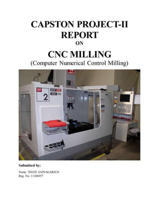
- 1. CAPSTON PROJECT-II REPORT ON CNC MILLING (Computer Numerical Control Milling) Submitted by: Name: THATI SAINAGARJUN Reg. No: 11306957
- 2. CONTENT 1. Introduction 2. History 3. Organizational Profile 4. Computer Numerical Control (CNC) 5. Elements of a CNC 6. CNC Milling 7. Part Programming for CNC 8. Drilling Program 9. Parts Suitable on CNC Machines 10. Environmental Control for CNC Machines 11. Applications 12. Advantages 13. Disadvantages
- 3. INTRODUCTION Central Institute of Hand Tool Welcome to CIHT. Our aim is to provide technology support services and trained manpower to engineering industry in general and the hand tools industries in particular to achieve global standards. CIHT is an autonomous organization. CIHT is a National Institute. CIHT was established in 1983 with assistance from UNDP, Government of India and Government of Punjab. CIHT is aspiring for latest technology to be a leader in region.
- 4. HISTORY Central Institute of Hand Tools was established in 1983 with assistance from United Nations development program (UNDP), government of India and government of Punjab. It is an autonomous organization under Ministry of MSME government of India and is an Institute of national importance in the area of Hand tools technology. The main objective of central institute of hand tools is to provide technology support, services and trained man power to engineering industry in general and to the hand tools industry in particular to achieve global manufacturing standards. The institute is managed by the governing council appointed by the govt. of India, with development commissioner, MSME as ex-officio chairman of the institute. The Principle Director is the chief executive officer of the institute; other G.C members include the govt. officials and the renowned industrialists from the industry. OrganizationalProfile Hand Tools Industry consists of organized, small scale and cottage sector. About 80 % of small scale and cottage sector is located in and around Jalandhar in Punjab, Nagaur in Rajasthan and Purulia in West Bengal. The Hand Tools Industries are playing a vital role in economic development and earning valuable foreign exchange for the country. With a view to provide technology support services to engineering industry in general and the hand tools industries in particular, the Government of India has set up Central Institute of Hand Tools as a National Institute in Jalandhar, in the state of Punjab as an autonomous organization with the assistance of U.N.D.P and Govt. of Punjab. The management of the institute rests with the Governing Council appointed by the Govt. of India, with Development Commissioner, small scale industries as ex-officio chairman of the institute. The Principal Director is the Chief Executive Officer of the Institute. Other members include the Govt. officials and the industrialists from the industry.
- 5. COMPUTER NUMERICAL CONTROL (CNC) Computer Numerical Control (CNC) is one in which the functions and motions of a machine tool are controlled by means of a prepared program containing coded alphanumeric data. CNC can control the motions of the work piece or tool, the input parameters such as feed, depth offcut, speed, and the functions such as turning spindle on/off, turning coolant on/off.
- 6. ELEMENTS OF A CNC A CNC system consists of three basic components: 1. Part program 2. Machine Control Unit (MCU) 3. Machine tool (lathe, drill press, milling machine etc.) A typical numerical control system for a milling machine Part Program The part program is a detailed set of commands to be followed by the machine tool. Each command specifies a position in the Cartesian coordinate system (x,y,z) or motion (work piece travel or cutting tool travel), machining parameters and on/off function. Part programmers should be well versed with machine tools, machining processes, effects of process variables, and limitations of CNC controls. The part program is written manually or by using computer assisted language such as APT (Automated Programming Tool). Machine Control Unit The machine control unit (MCU) is a microcomputer that stores the program and executes the commands into actions by the machine tool. The MCU consists of two main units: the data processing unit (DPU) and the control loops unit (CLU). The DPU software includes control system software, calculation algorithms, translation software that converts the part program into a usable format for the MCU, interpolation algorithm to achieve smooth motion of the cutter, editing
- 7. of part program (in case of errors and changes). The DPU processes the data from the part program and provides it to the CLU which operates the drives attached to the machine lead screws and receives feedback signals on the actual position and velocity of each one of the axes. A driver (dc motor) and a feedback device are attached to the lead screw. The CLU consists of the circuits for position and velocity control loops, deceleration and backlash take up, function controls such as spindle on/off. Machine Tool The machine tool could be one of the following: lathe, milling machine, laser, plasma, coordinate measuring machine etc. Figure 3 shows that a right-hand coordinate system is used to describe the motions of a machine tool. There are three linear axes (x,y,z), three rotational axes (i,j,k), and other axes such as tilt (9) are possible. For example, a 5-axis machine implies any combination of x, y, z, i, j, k, and 𝜃. Right-hand coordinate system used in drill press and lathe CNC Milling Milling is the machining process of using rotary cutters to remove material from a work piece advancing (or feeding) in a direction at an angle with the axis of the tool. It covers a wide variety of different operations and machines, on scales from small individual parts to large, heavy-duty gang milling operations. It is one of the most commonly used processes in industry and machine shops today for machining parts to precise sizes and shapes.
- 8. Process: Milling operates on the principle of rotary motion. A milling cutter is spun about an axis while a work piece is advanced through it in such a way that the blades of the cutter are able to shave chips of material with each pass. Milling processes are designed such that the cutter makes many individual cuts on the material in a single run; this may be accomplished by using a cutter with many teeth, spinning the cutter at high speed, or advancing the material through the cutter slowly. Most often it is some combination of the three. The speed at which the piece advances through the cutter is called feed rate, or just feed; it is most often measured in length of material per full revolution of the cutter. As material passes through the cutting area of a milling machine, the blades of the cutter take swarfs of material at regular intervals. This non-continuous cutting operation means that no surface cut by a milling machine will ever be completely smooth; at a very close level (microscopic for very fine feed rates), it will always contain regular ridges. These ridges are known as revolution marks, because rather than being caused by the individual teeth of the cutter, they are caused by irregularities present in the cutter and milling machine; these irregularities amount to the cutter being at effectively different heights above the work piece at each point in its rotation. The height and occurrence of these ridges can be calculated from the diameter of the cutter and the feed. These revolution ridges create the roughness associated with surface finish. Types: Mill orientation is the primary classification for milling machines. The two basic configurations are vertical and horizontal. However, there are alternate classifications according to method of control, size, and purpose and power source. Vertical mill: In the vertical mill the spindle axis is vertically oriented. Milling cutters are held in the spindle and rotate on its axis. The spindle can generally be extended (or the table can be raised/lowered, giving the same effect), allowing plunge cuts and drilling.
- 9. There are two subcategories of vertical mills: (a) The bed mill and (b) The turret mill. Horizontal Mill: A horizontal mill has the same sort of x–y table, but the cutters are mounted on a horizontal arbor (see Arbor milling) across the table. Many horizontal mills also feature a built-in rotary table that allows milling at various angles; this feature is called a universal table. While end mills and the other types of tools available to a vertical mill may be used in a horizontal mill, their real advantage lies in arbor-mounted cutters, called side and face mills, which have a cross section rather like a circular saw, but are generally wider and smaller in diameter. Because the cutters have good support from the arbor and have a larger cross-sectional area than an end mill, quite heavy cuts can be taken enabling rapid material removal rates. These are used to mill grooves and slots. Plain mills are used to shape flat surfaces. Several cutters may be ganged together on the arbor to mill a complex shape of slots and planes. Special cutters can also cut grooves, bevels, radii, or indeed any section desired. These specialty cutters tend to be expensive. Simplex mills have one spindle, and duplex mills have two. It is also easier to cut gears on a horizontal mill. Some horizontal milling machines are equipped with a power-take-off provision on the table. This allows the table feed to be synchronized to a rotary fixture, enabling the milling of spiral features such as hypoid gears. PART PROGRAMMING FOR CNC The transfer of an engineering blueprint of a product to a part program can be performed manually using a calculator or with the assistance of a computer language. A part programmer must have an extensive knowledge of the machining processes and the capabilities of the machine tools. In this section, we describe how the part programmers execute manually the part programs. First, the machining parameters are determined. Second, the optimal sequence of operations is evaluated. Third, the tool path is calculated. Fourth, a program is written. Each line of the program, referred to as a block, contains the required data for transfer from one point to the next. A typical line for a program is given below. N001 G91 X -5.0 Y7.0 F100 S200 T01 M03 The significance of each term is explained below. Sequence Number (N): Consisting of typically three digits, its purpose is to identify the specific machining operation through the block number particularly when testing a part program. PreparatoryFunction (G): It prepares the MCU circuits to perform a specific operation. The G-codes some are shown,
- 10. G-Codes: G00 – Rapid positioning G01 – Linear Interpolation G02 – Circular Interpolation clock wise G03 – Circular Interpolation counter clock wise G04 – Dwell G09 – Exact stop G10 – Data setting G15 – Polar coordinates command cancel G16 – Polar Coordinates command G17 – XY plane selection G18 – ZX plane selection G19 – YZ plane selection G20 – Inch input G21 – Metric input G28 – Return to reference position G33 – Thread Cutting G40 – Cutter compensation cancel G41 – Cutter compensation left G42 – Cutter compensation right G43 – Tool length compensation + direction G44 – Tool length compensation – direction G49 – Tool length compensation cancel G52 – Local coordinate system G53 – Machine coordinate system selection G54 – Work piece coordinate system 1 selection G55 – Work piece coordinate system 2 selection G56 – Work piece coordinate system 3 selection G57 – Work piece coordinate system 4 selection G58 – Work piece coordinate system 5 selection G59 – Work piece coordinate system 6 selection G73 – Peck drilling cycle G76 – Fine boring cycle G80 – Canned cycle cancel G81 – Drilling cycle G82 – Counter boring cycle G84 – tapping cycle G85 – Boring cycle G87 – Back boring cycle G90 – Absolute command G91 – Incremental command G94 – Feed per minute G95 – Feed per rotation
- 11. G98 – Return to initial point in canned cycle G99 – Return to R point in canned cycle Dimension Words: Distance dimension words, X, Y, Z. These are expressed either by incremental or absolute mode. In the above block, X moves a distance of 5 in. in the negative direction while Y moves a distance of 7 in. in the positive direction. Other axes remain stationary. In some systems, actual distances are used. Feedrate (F): It is expressed in in/min or mm/min and, is used in contouring or point-to-point or straight-cut systems. For example, a feedrate of F100 implies 100 in/min or 100 mm/min. Feedrates are independent of spindle speed. Spindle speed(S): Programmed in rev/min, it is expressed as RPM or by a three-digit code number that is related to the RPM. Tool(T): Consisting of a maximum of five digits, each cutting tool has a different code number. The tool is automatically selected by the automatic tool changer when the code number is programmed in a block. Miscellaneous Function(M): Consisting of two digits, this word relates to the movement of the machine in terms of spindle on/off, coolant on/off etc., M-Codes: M00 – Program Stop M01 – Optional stop M02 – End of program M03 – Clockwise spindle M04 – Counter clockwise spindle M05 – Spindle stop M06 – Tool change M08 – Coolant on M09 – Coolant off M30 – End of program & rewind TYPES OF PART PROGRAMMING: (a) Manual part programming, and (b) Computer aided part programming.
- 12. Manual Part Programming: The programmer first prepares the program manuscript in a standard format. Manuscripts are typed with a device known as flexo writer, which is also used to type the program instructions. After the program is typed, the punched tape is prepared on the flexo writer. Complex shaped components require tedious calculations. This type of programming is carried out for simple machining parts produced on point-to-point machine tool. To be able to create a part program manually, need the following information : (a) Knowledge about various manufacturing processes and machines. (b) Sequence of operations to be performed for a given component. (c) Knowledge of the selection of cutting parameters. (d) Editing the part program according to the design changes. (e) Knowledge about the codes and functions used in part programs. Computer Aided Part Programming: If the complex-shaped component requires calculations to produce the component are done by the programming software contained in the computer. The programmer communicates with this system through the system language, which is based on words. There are various programming languages developed in the recent past, such as APT (Automatically Programmed Tools), ADAPT, AUTOSPOT, COMPAT-II, 2CL, ROMANCE, SPLIT is used for writing a computer programme, which has English like statements. A translator known as compiler program is used to translate it in a form acceptable to MCU. The programmer has to do only following things : (a) Define the work part geometry. (b) Defining the repetition work. (c) Specifying the operation sequence. Over the past years, lot of effort is devoted to automate the part programme generation. With the development of the CAD (Computer Aided Design)/CAM (Computer Aided Manufacturing) system, interactive graphic system is integrated with the NC part programming. Graphic based software using menu driven technique improves the user friendliness. The part programmer can create the geometrical model in the CAM package or directly extract the geometrical model from the CAD/CAM database. Built in tool motion commands can assist the part programmer to calculate the tool paths automatically. The programmer can verify the tool paths through the graphic display using the animation function of the CAM system. It greatly enhances the speed and accuracy in tool path generation.
- 13. DRILLING PROGRAM: N001 G00 G17 G21 G90 G98 G94; (Rapid positioning, xy plane, metric input, absolute command) N002 G00 G54 X00 Y00 Z50; (work piece coordinate system) N003 M03 S500 M08;
- 14. (spindle on, speed, coolent on) N004 G00 Z05; N005 G83 Q3 R5 X50 Y50 Z-20 F100; (drilling cycle, number tymes drilling, radius of drill, feed) N006 G00 G80 Z50; (canned cycle cancel) N007 M05 M09; (spindle stop, coolent off) N008 M30; (end of program) PARTS SUITABLE ON CNC MACHINES The following parts are usually made in practice on the CNC Machines: (a) Aerospace equipment’s. (b) Automobile Parts. (c) Complex shapes. (d) Electronic industry uses CNC e.g. Printed circuit board. (e) Electrical industry uses CNC e.g. Coil winding. (f) For small to medium batch quantity. (g) Where the set-ups are very large. (h) Where the tool storage is a problem. (i) Where much metal needs to be removed. (j) When the part geometry is so complex. (k) The operations are very complex. (l) For parts subjected to regularly design changes. (m) When the inspection is required 100%. (n) When lead time does not permit the conventional tooling manufacture. (o) When the machining time is very less as compared to down. (p) Where tool storage is a problem.
- 15. ENVIRONMENTAL CONTROL FOR CNC MACHINES (a) Well air circulation. (b) Working temperature should be within control limits. (c) Space should not be congested but should be quite open. (d) Electrical power supply should be regulated. (e) There should be proper disposal point for scrap. (f) There should not be presence of noisy source near to the machine. (g) There should not be presence of harmful chemicals near to the machine. (h) Proper lighting to the system. (i) The machine should be protected from the moisture. (j) There should not be presence of vibrating source near to the machine. (l) Floor should be cleaned free from oily and greased. (m) Trained person should operate the machine. (n) Dust free floor space and environment. (o) Sufficient supply of coolant required during machining. Applications: The applications of CNC include both for machine tool as well as non-machine tool areas. In the machine tool category, CNC is widely used for lathe, drill press, milling machine, grinding unit, laser, sheet-metal press working machine, tube bending machine etc. Highly automated machine tools such as turning center and machining center which change the cutting tools automatically under CNC control have been developed. In the non-machine tool category, CNC applications include welding machines (arc and resistance), coordinate measuring machine, electronic assembly, tape laying and filament winding machines for composites etc. Advantages: Accuracy When programmed correctly, CNC machines are usually 100% correct with what they produce. They: produce parts to maximise accuracy provide good positional accuracy and repeatability provide a high degree of quality because of their accuracy and their ability to reuse programs.
- 16. Simplicity CNC machines are not all that difficult to use once you learn how. For example: complex jigs and fixtures are not required in all areas since fewer jigs are used, the actual storage requirements are reduced lower tooling costs since there is less need for complex jigs and fixtures once the first piece has passed inspection, minimal inspection is required on subsequent parts advanced machine control and programming capabilities allow for complex machining operations to be more easily accomplished. Time Using CNC machines effectively reduces the amount of time take to produce furniture items. CNC machines: enable the operator to make changes or improvements with a minimum of delay or expense reduce waste as errors due to operator fatigue, interruptions and other factors are less likely to occur improve production planning as they can often perform work at one setting that would normally require several conventional machines reduce lead time as a result of lower tooling costs. Disadvantages: Cost As with any business, costs are always a factor. CNC machinery: costs quite a lot more than conventional machinery does not eliminate the need for expensive tools The parts (ie machines and tooling) are costly and their purchase requires extensive justification. It is expensive to repair. Errors CNC machines do not totally eliminate errors. Operators can still push the wrong buttons, make incorrect alignments and fail to locate parts properly on a jig.