The document discusses CNC programming and G-codes. It provides information on:
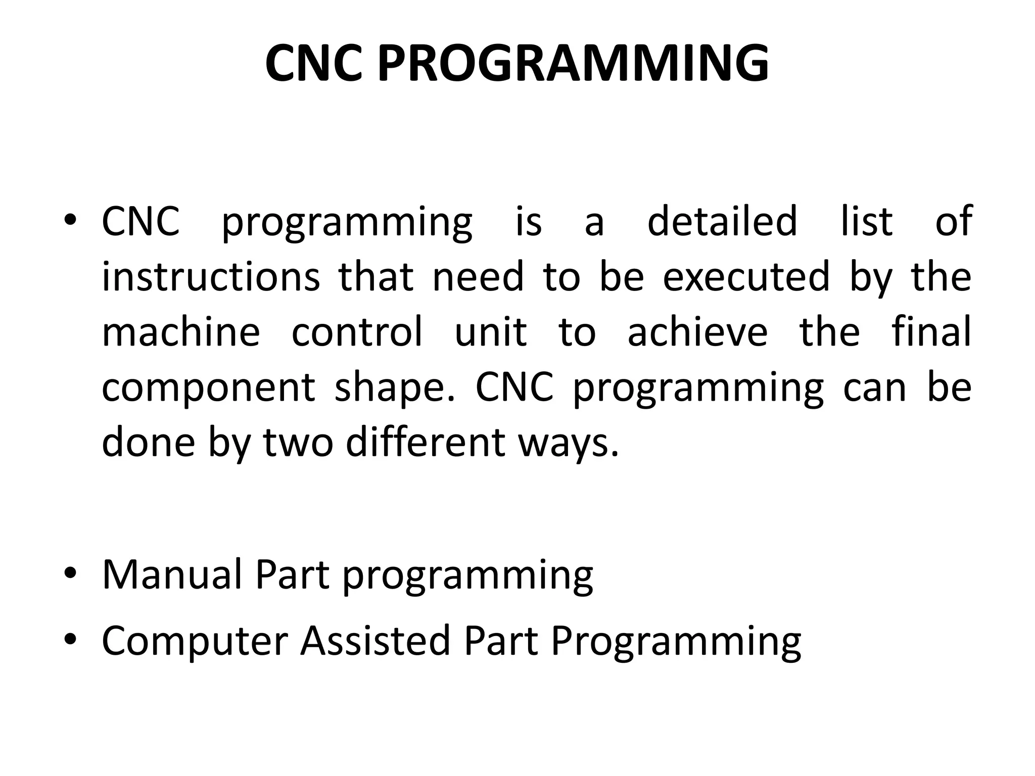
1) CNC programming can be done manually or with computer assistance and involves generating a detailed list of instructions for the machine control unit.
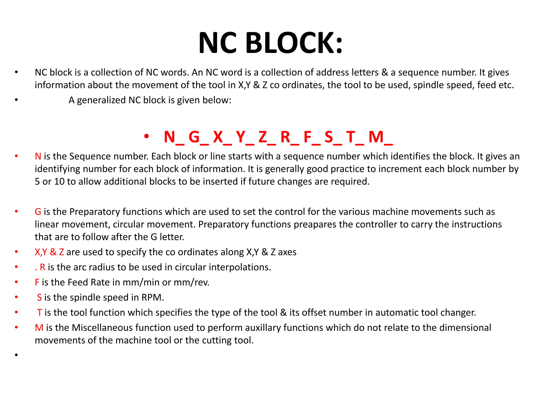
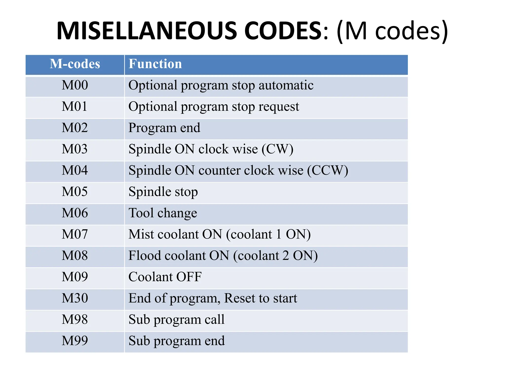
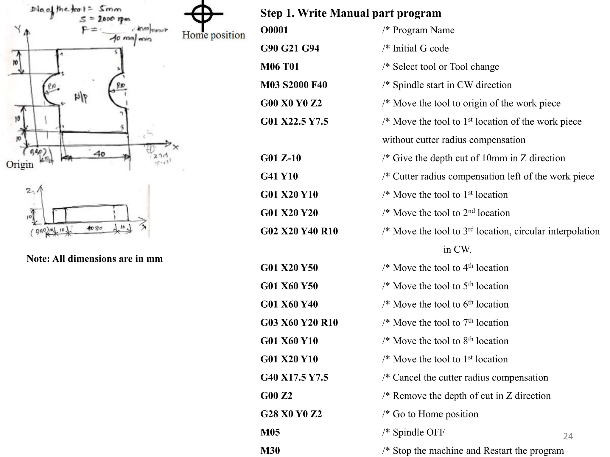
2) An NC block contains NC words which provide information on tool movements, speeds, and functions using address letters like X, Y, Z, R, F, S, T, and M.
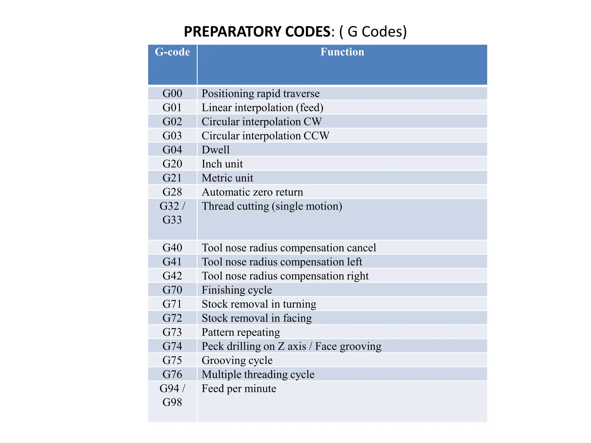
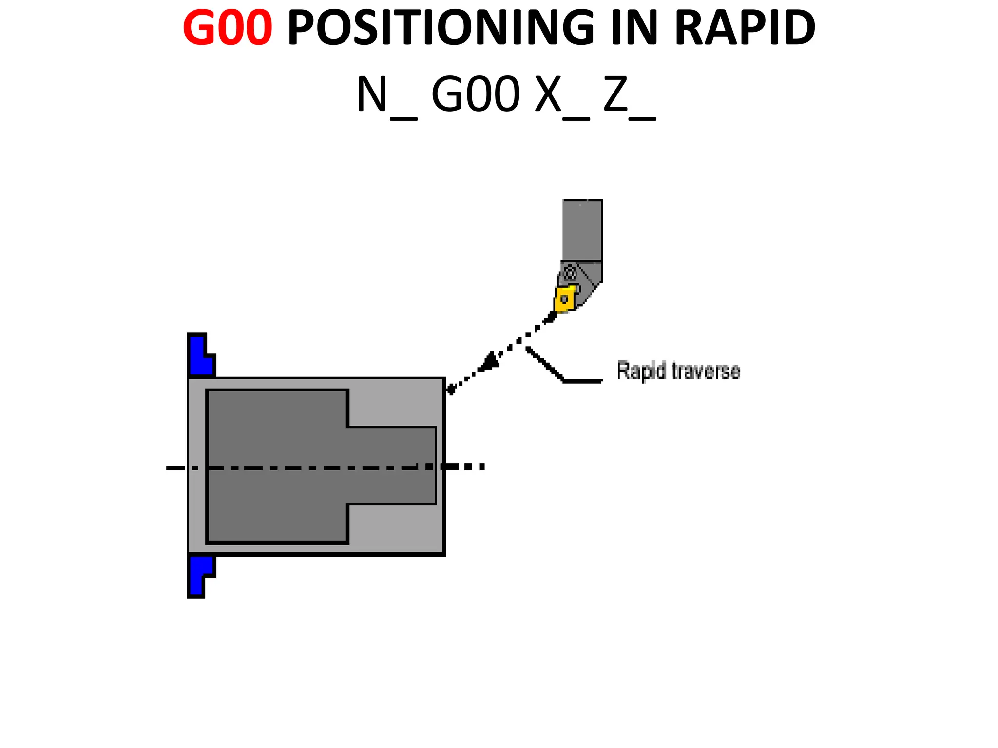
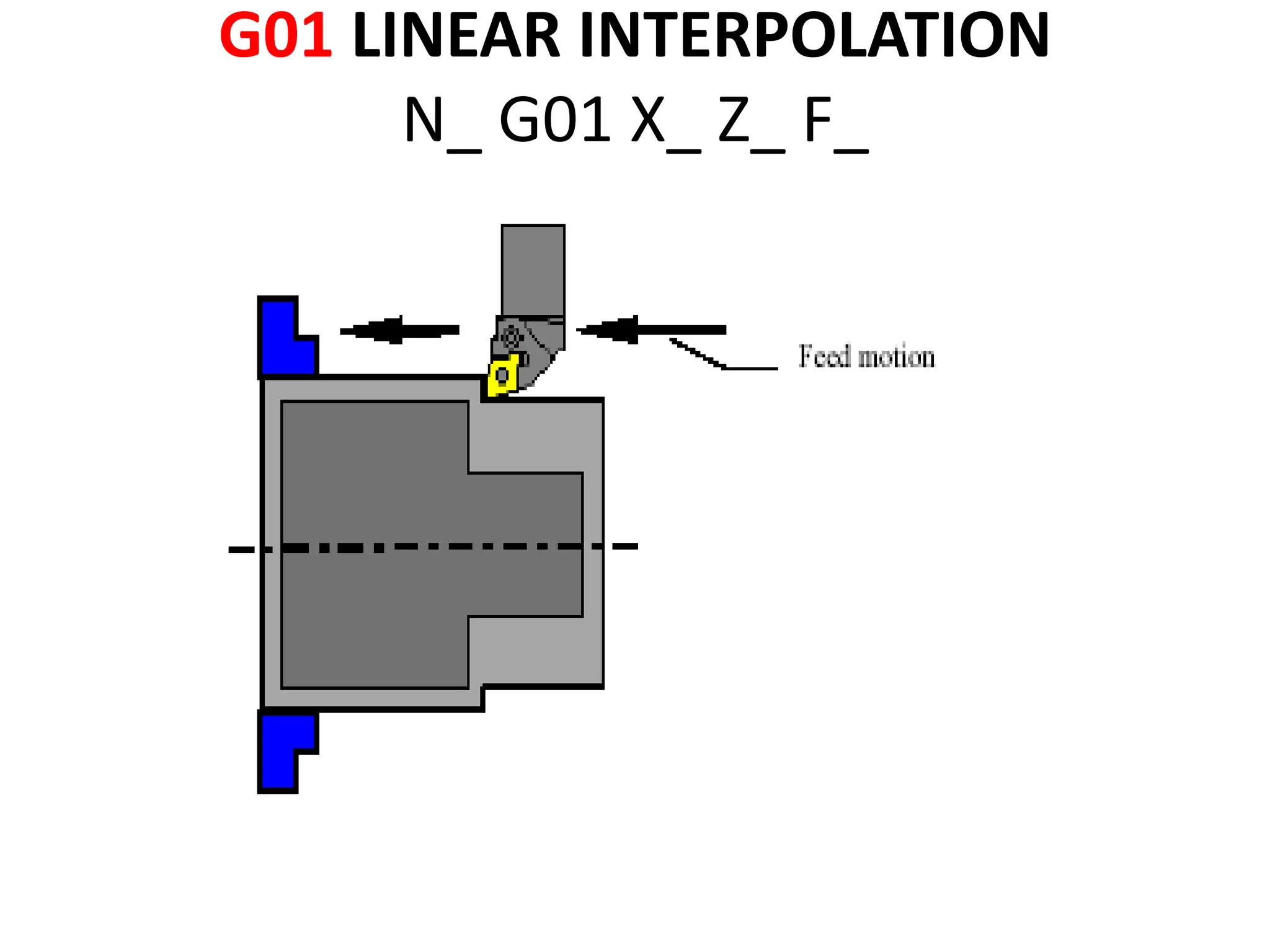
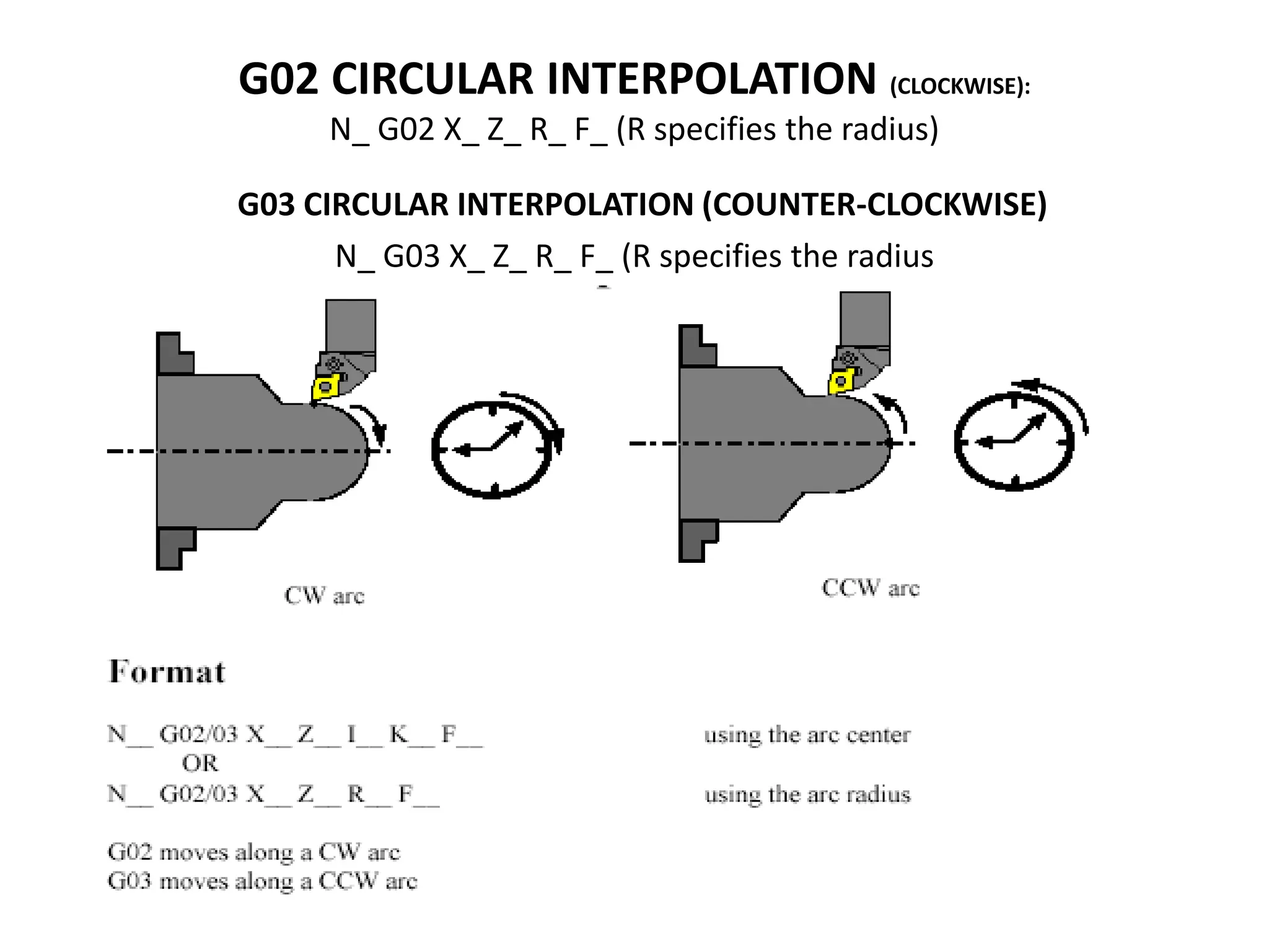
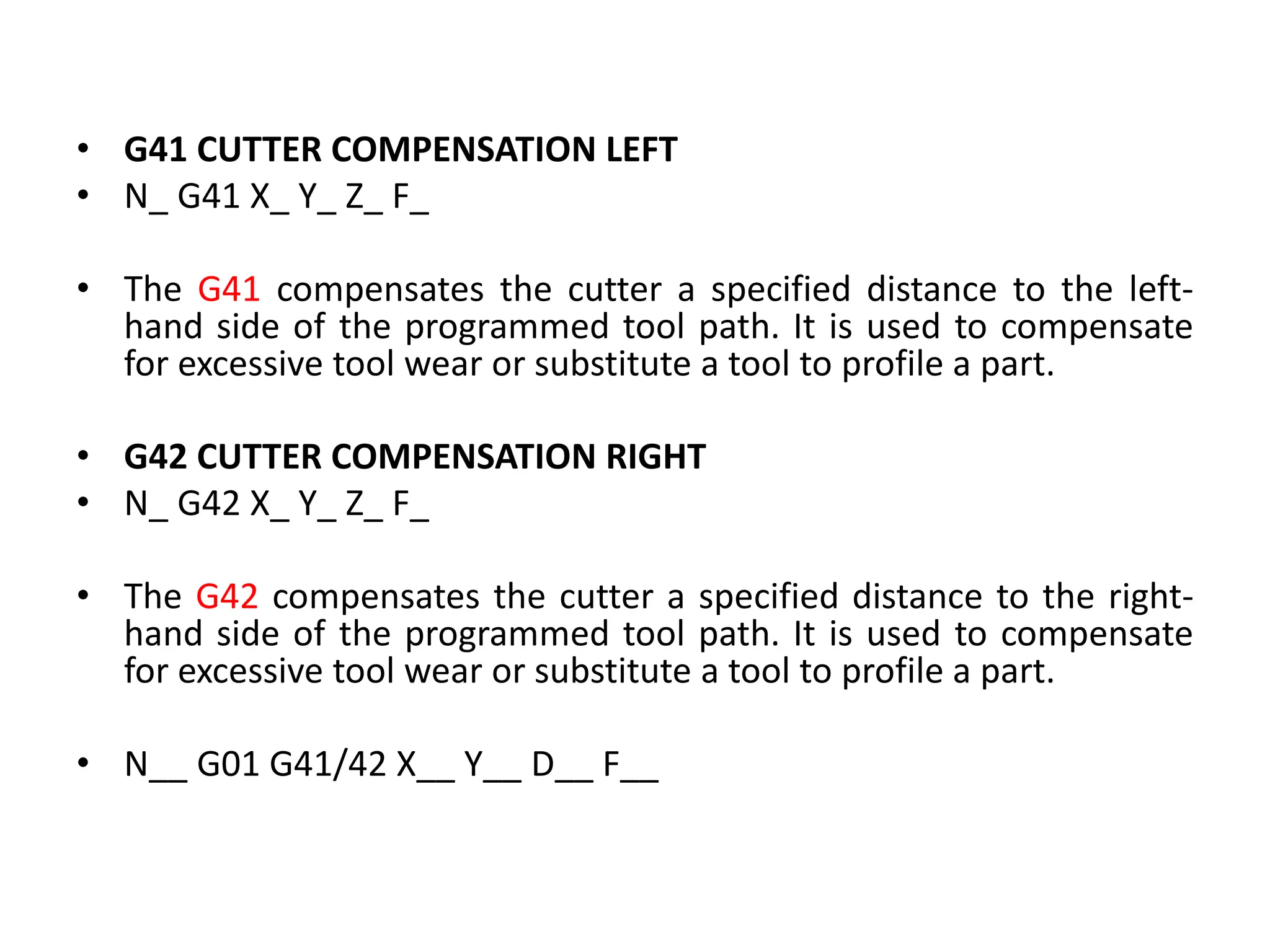
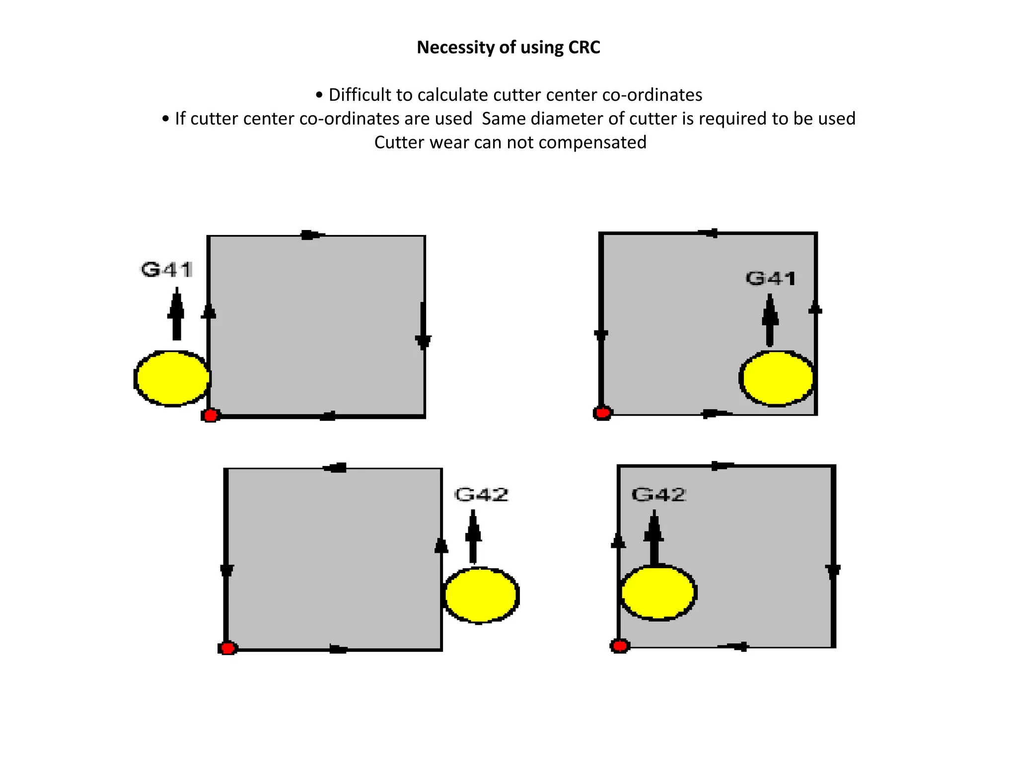
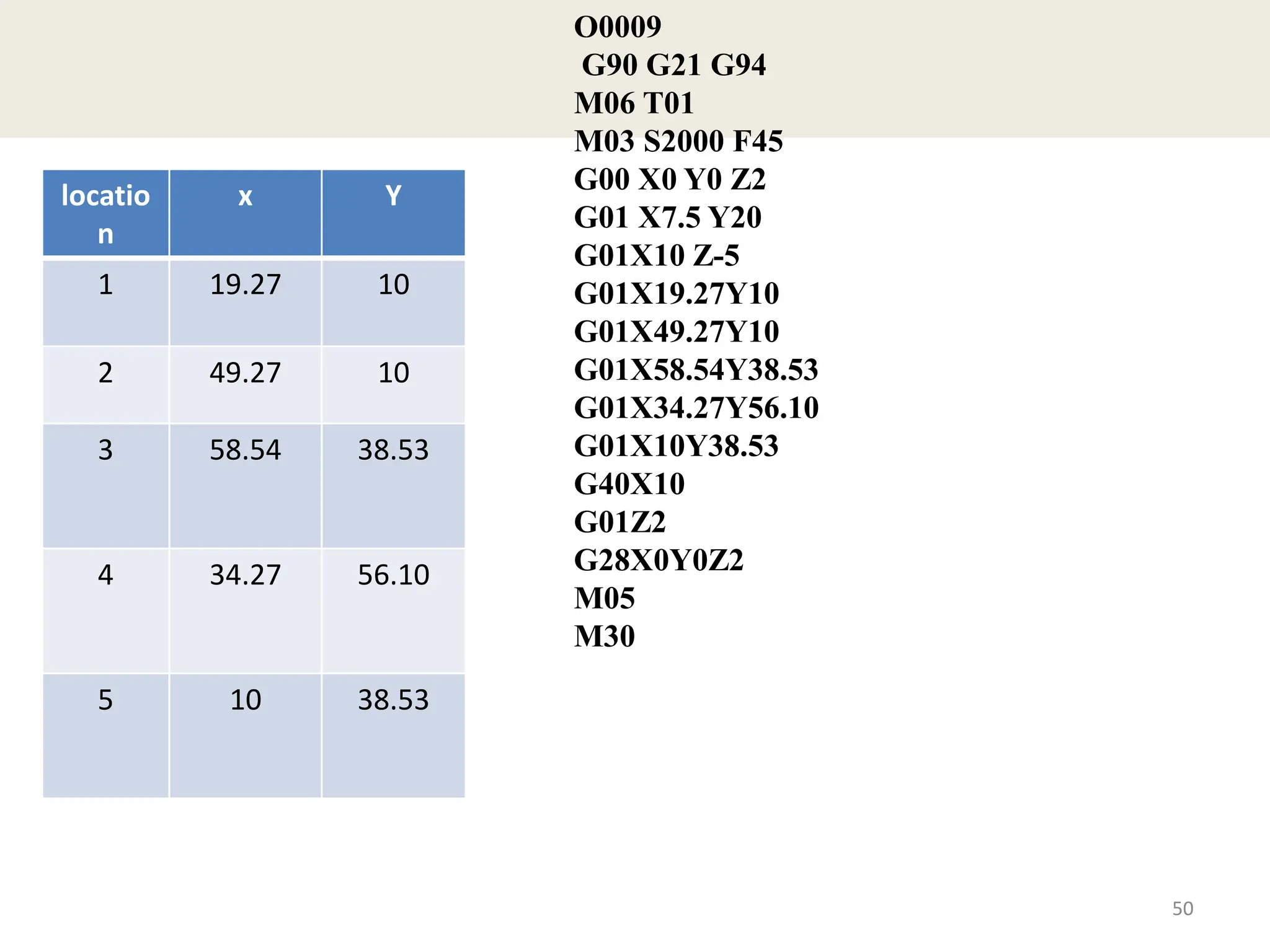
3) Common G-codes include G00 for rapid positioning, G01 for linear interpolation, G02/G03 for clockwise and counter-clockwise circular interpolation, and G40-G42 for tool nose radius compensation.
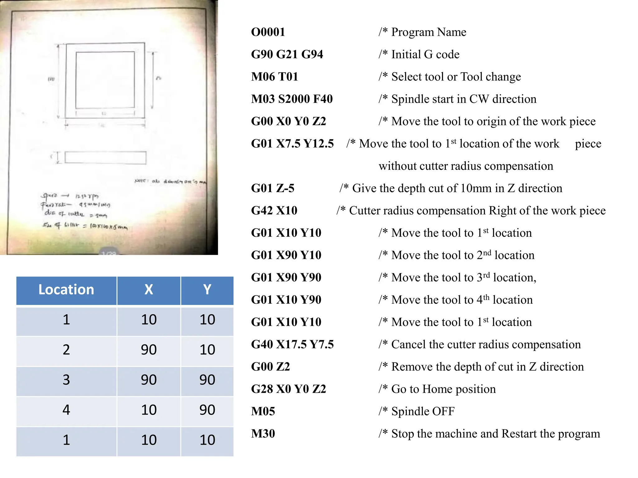
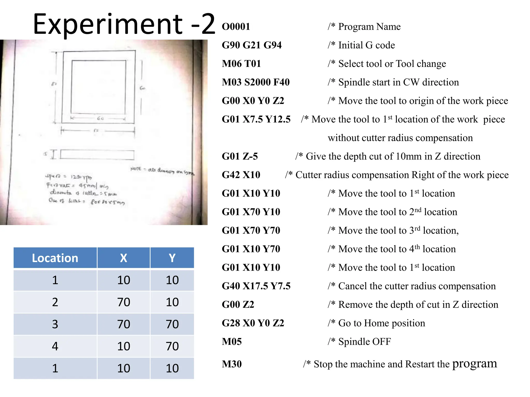
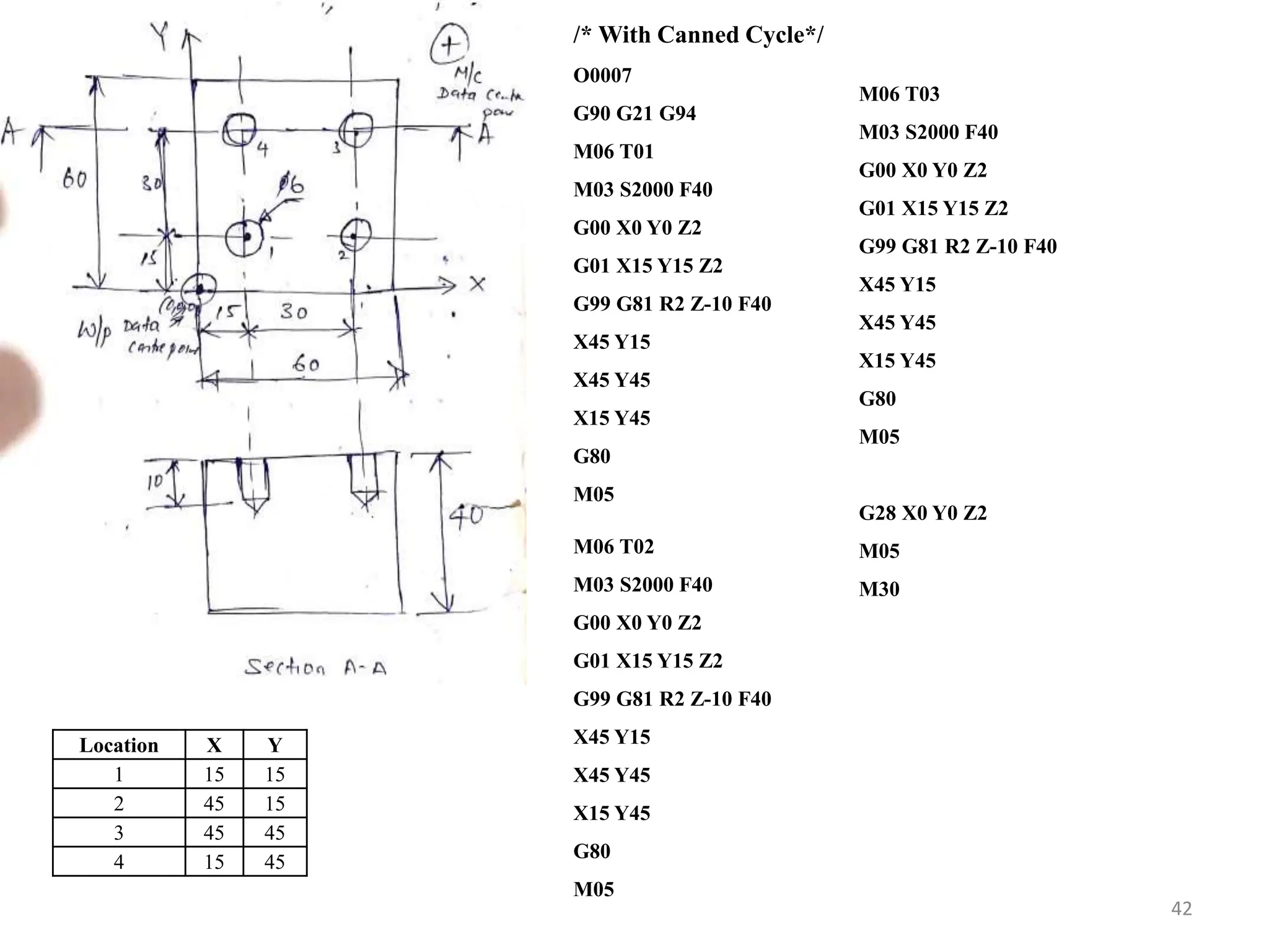
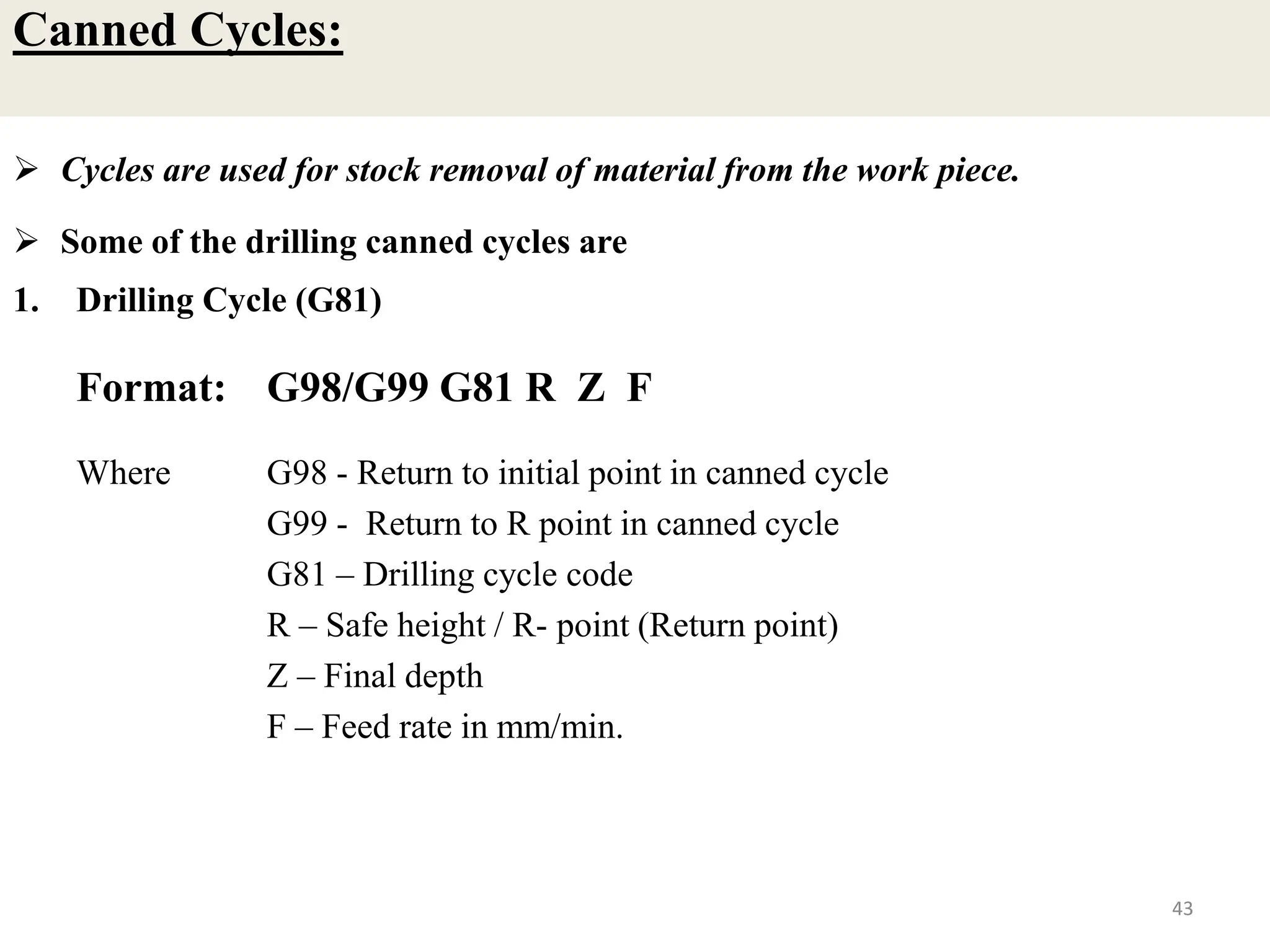
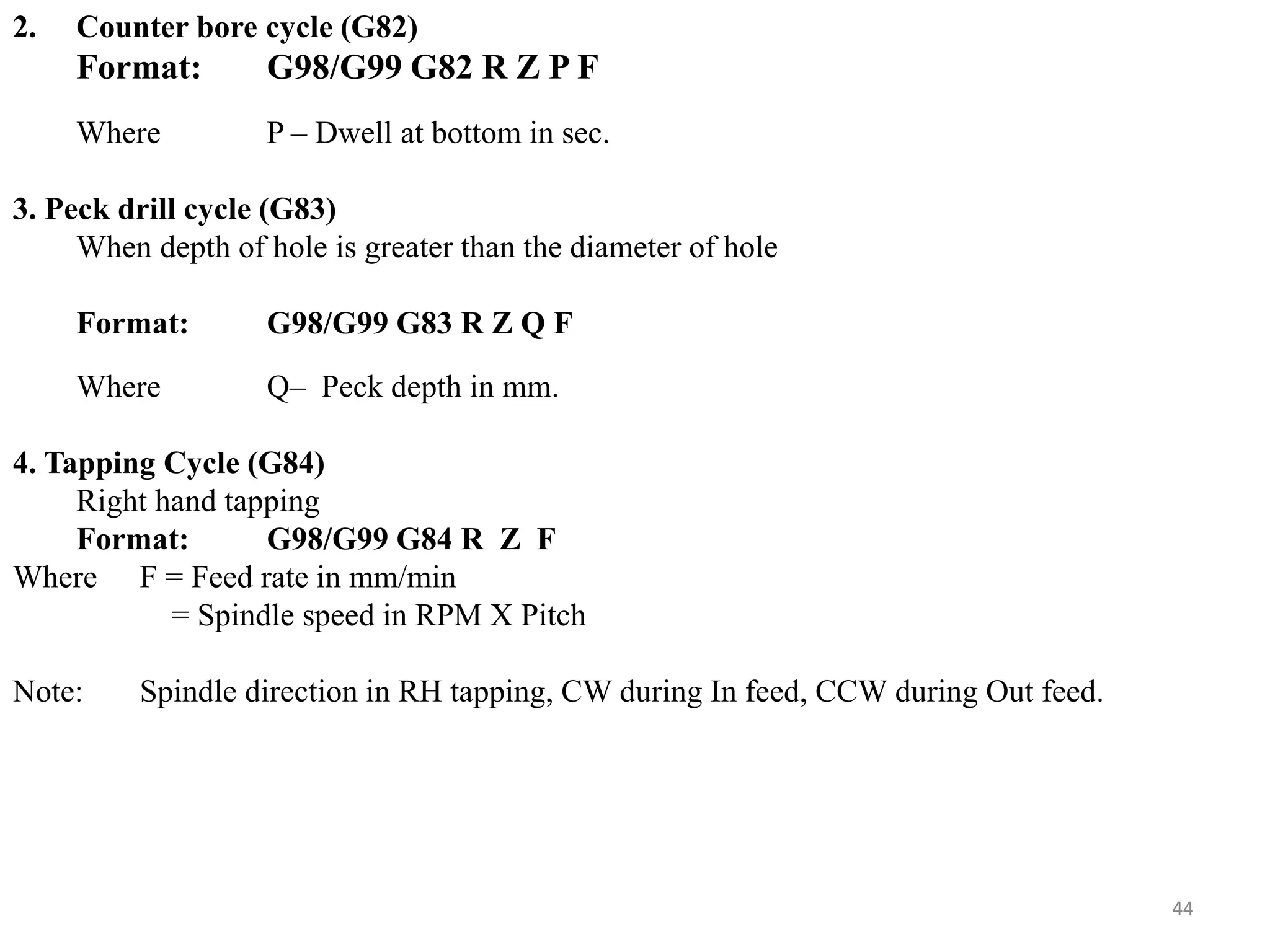
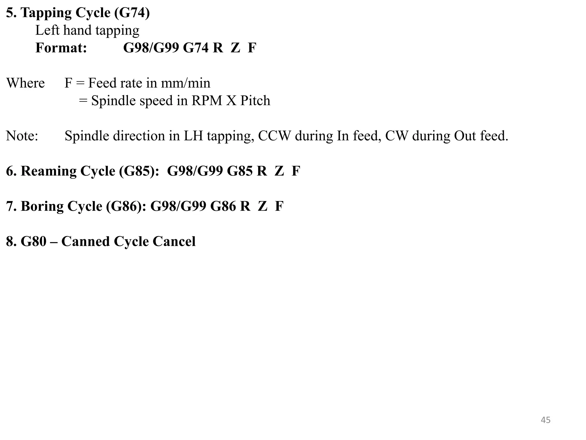
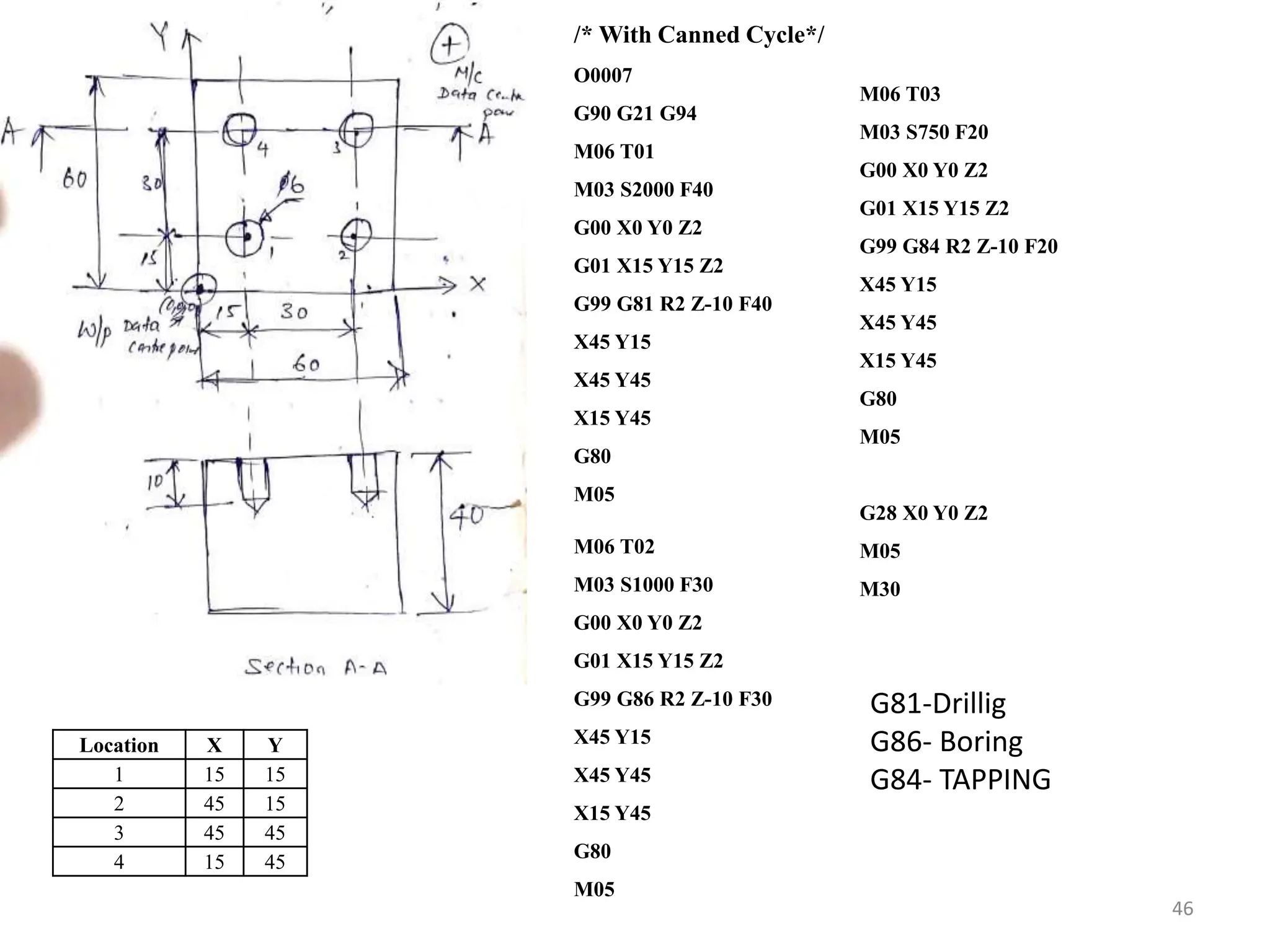
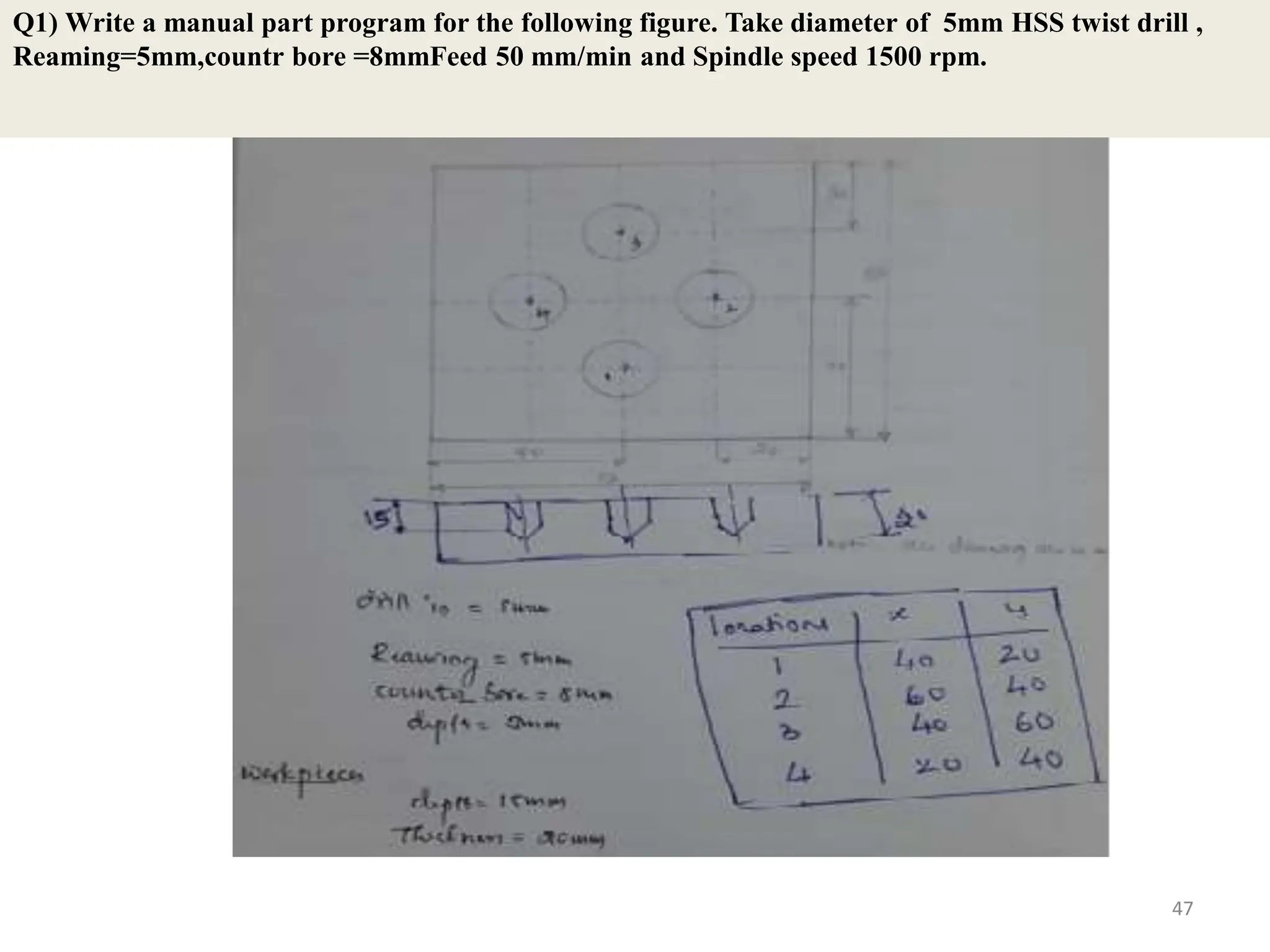
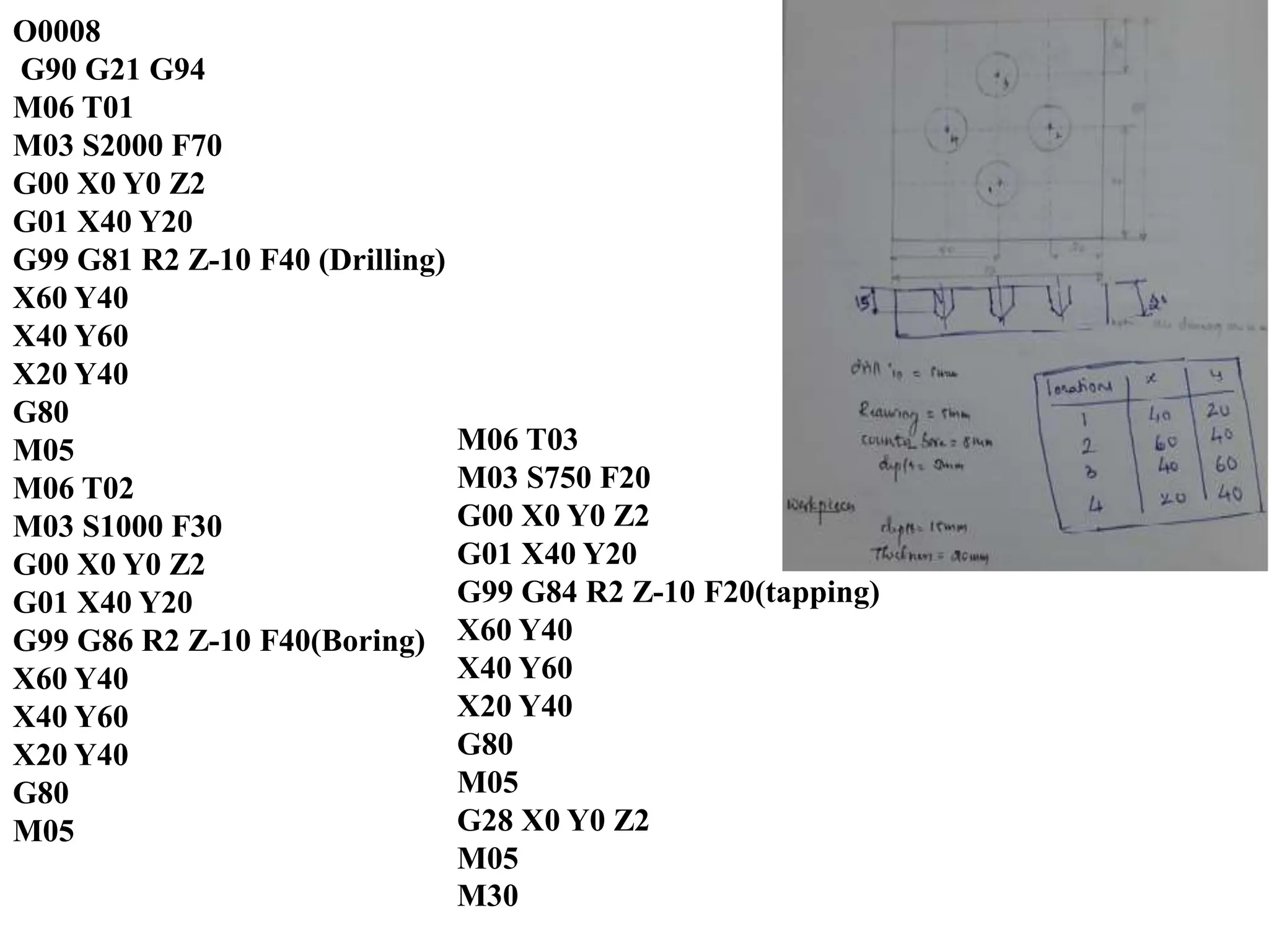
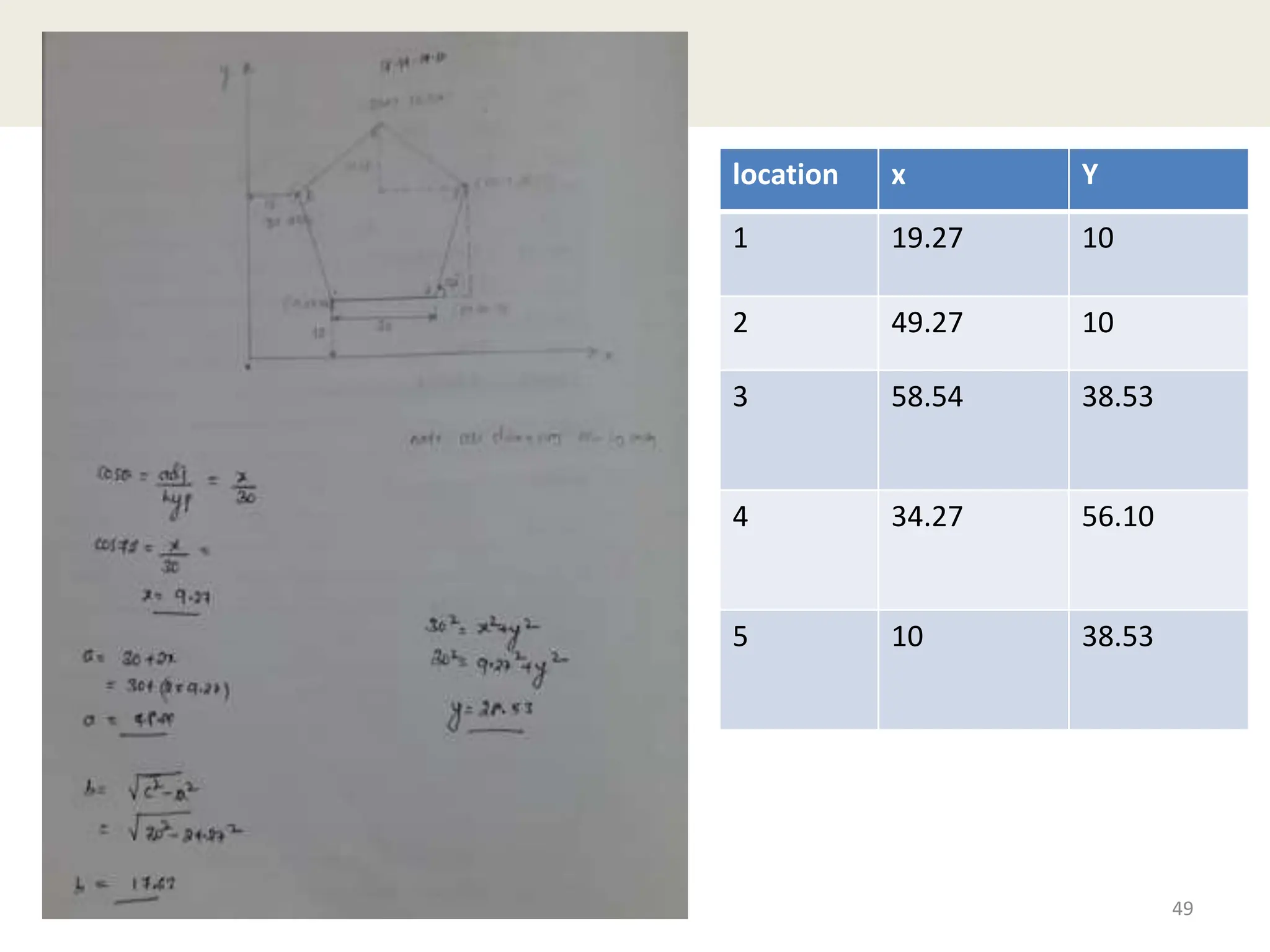
4) The document gives examples of G-code


![[BROCHURE] Italy Tour Project | @SlideON](https://cdn.slidesharecdn.com/ss_thumbnails/brochure8-251215152319-2805af68-thumbnail.jpg?width=640&height=640&fit=bounds)


