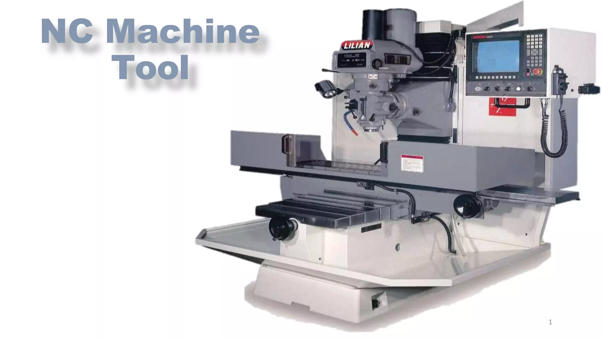
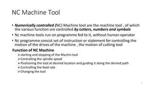
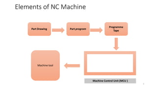
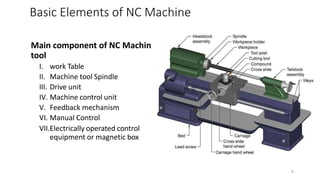
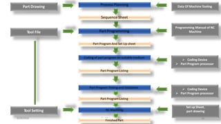
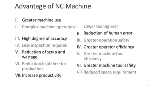
NC Machine
Tool
1
2
• Numerically controlled (NC) Machine tool are the machine tool , of which
the various function are controlled by Letters, numbers and symbols
• Nc machine tools run on programme fed to it, without human operator
• Nc programme consist set of instruction or statement for controlling the
motion of the drives of the machine , the motion of cutting tool
Function of NC Machine
starting and stopping of the Machin tool
Controlling the spindle speed
Positioning the tool at desired location and guiding it along the desired path
Controlling the feed rate
Changing the tool
NC Machine Tool
Elements of NC Machine
Part Drawing
Machine tool
Programme
Tape
Part program
Machine Control Unit (MCU )
3
4
(1)Part Drawing and Part Programming
• Part programme is set of step by step instruction to the machine tool for
caring out the operation.
• Part program is written by using part Drawing and cutting process parameter
• The set of instruction includes
Instruction position of machine tool spindle with respect to the work table
Instruction for cutting operation
Instruction for selection of spindle speed, cutting tool etc.
Method of Part Programing
I. Manual Part programming
II. Computer aided Part programming
Basic Elements of NC Machine
(2) Programme Tape
• Part programme is entered on the programme tape
• The tape is a long wound roll of the one inch with.
• The programme is entered on the tape in the form of punched
holes ,holes punched with the help of punching machine.
• Now a day punchline tape is replaced with magnetic cassetes ,
floppy disc , pen drive , hard drive
Basic Elements of NC Machine
5
6
(3)Machine control unit (MCU)
• MCU is heart of NC/CNC machine which consist of some electronics
hard wear that read the NC programme , interpret it and conversely
translates it for mechanical action of machine tool
• A typical MCU consist following units
 Input or tape reader
 memory
 processor
 output channels
 control panel
 feedback channels
• MCU performs Following functions
• read coded instruction
• Decode coded instruction
• implement interpolation (linier ,circular, and Helical )v to generate axis
motion commands
• feed axis motion command to amplified circuits for driving the axis
mechanism
• Received the signals of position and speed for each drive axis
• implement auxiliary control function such as coolant or spindle on/off , and
tool change .
Basic Elements of NC Machine
7
(4) Machine Tool
• The Machine tool is operated by MCU
• following function may automated by Machine tool
starting and stopping of the machine tool spindle
controlling the spindle speed
Positioning of tool tip at desires locations and guiding it along the desired path by
automatic control of the slide motion
Controlling the feed rate
Changing the tool
Basic Elements of NC Machine
Main component of NC Machin
tool
I. work Table
II. Machine tool Spindle
III. Drive unit
IV. Machine control unit
V. Feedback mechanism
VI. Manual Control
VII.Electrically operated control
equipment or magnetic box
8
Basic Elements of NC Machine
9
Conventional machining NC machining
Accuracy and repeatability are operator
dependent
Accuracy and repeatability are independent of
opertor
Manual operation Automated operation
Operation is controlled by operator Operation is controlled by MCU
Difficult to make complicated profiles Very complicated profiles can be generated easily
Very difficult setting is needed to achieve high
accuracy
High accuracy can be easily achieved by simple
setting
Difficult to control more than one axis at a time Many working axes can be controlled easily at
time
Axis movement is either by feed box/rack and
pinion arrangement
Servomotors are used to drive each axis
Only step by step speeds by manual shifiting is
possible
Constant surface speed to complete a machining
process
Position accuracy is poor and depend on the skill
of operator
Very high positioning accuracy
Poor repeatability and depend on the skill of
operator
Very high repatability for components
Productivity can not be estimated as cycle.depends
mood and attitude of the operator on each day
Productivity can be estimated as cycle time is
definite
Production line can not be automated Production line can be automated
Nc Machine
Open loop type
According to
control loop
feedback system
Close loop type
According to
type of tool
motion
Finite
positioning
control
Point to point
Straight cut
Continuous
path control
Two axis
contouring
Two and half
axes contouring
Three axes
contouring
Multi-axis
Contouring
According to
Program method
Absolute
programming
Incremental
programming
According to type
of controller
Nc based
controlling
system
Cnc based
controlling
system
10
(a) Open loop type Nc Machine
This type pf control have only motion control without feed back
mechanism
The open loop system do not have feedback mechanism
Ex: drilling Machine
1.According to control loop feedback system
11
Loop Systems for Controlling Tool
Movement
Schematic illustration of the components of an open-loop
12
(B) Close loop type Nc Machine
This type pf control have motion control with feed back mechanism
The close loop system have feedback mechanism which can accurately
controlling the drive system.
It drive system by comparing with input information until require position
achieved
Feed back is measured by monitoring device to determine the drive
displacement.
1.According to control loop feedback system
13
Loop Systems for Controlling Tool
Movement
Schematic illustration of the components of a closed-loop control system for a NC machine.
14
(A) Finite Position Control NC machine
1) Point to point NC Machine
• PTP is simplest of all control mode
• In this type movement of cutting tool
moves from one “Predefined position” to
another Predefined Position , while path
along which this tool moves irevenant.
• Specially used in local position base
operation i.e: drilling ,punching or welding
2. According to type of tool motion
A
y
X
o
B
15
(A)Finite Position Control NC
machine
(2)Straight cut NC machine
• It is extension of point to point control mode
with provision of straight line cut or machining
• This straight line cut is obtained by controlling
the movement of tool with controlled feed
rate in one of the axis direction at time
• Ex: face milling ,pocket milling , stepped
turning
2. According to type of tool motion
16
17
(B) Finite Position Control NC machine
2) Continuous path control NC Machine
• Used for continuous simulation and coordinate motion of cutting tool and workpiece
along different AXES
• Such control enable for machining of different contorting profile and curved surface
• Due to simultaneously controlling relative position pass trough the desired countering
path of the final shape of require product
Types of Continuous path control NC Machine
I. Two axes contouring
II. Two and half axes contouring
III. Three axes contouring
IV. Multi – axes countering
2. According to type of tool motion
Two axes contouring
• In this method tool is controlled
simultaneously in only two axes (X and Y )
2. According to type of tool motion
Two and half axes contouring
• In this method the plane of machining is
inclined to the plane of motion of tool (i.e. X –
Y plane)
z
y
Two axis counter
milling
z
18
y
Three Axes Contorting
• In this method tool is controlled simultaneously in only three
axes (X ,Y and Z )
• In this mode different type of interpolation techniques are used
to getting correct tool movement along path
• Application : turning and machining center , flame cutting
,welding , spark- erosion , sawing machine ,
2. According to type of tool motion
Multi - axes contouring
• In this method the tool orientation can be changed with
the tool motion .
• Ex : A six axes machine tool is capable of moving the tool
simultaneously along each primary axis and also rotate
about each primary axis at same time
y
19
18
Why programming needed ?
• For preparing programme ,it is necessary to specify the path tool
movement .
• Therefore a geometric data of a component is converted in to
machine understandable programme.
• Which gives specific path to tool on workpiece.
• Programing is the bridge between machine and humans.
Types of Programming method
a. Absolute programming NC machine system
b. Incremental Programming NC Machine system
3. According to Programming Method
20
Absolute programming NC machine system
• In absolute Programing system each point is always start from same
specific point.
• In this method first point (ZERO POINT or REFRENCE POINT ) is fixed.
• All Process Start from same reference point
3. According to Programming Method
34
20
10
10
25
40
1
0
Point X Coordinator Y Coordinator
P1 10 10
P2 25 20
P3 40 34
21
Incremental programming NC machine system
• In incremental Programing system each point is specified using the path
differential from the preceding point position.
• In this method first point (ZERO POINT or REFRENCE POINT ) is last point of
previous path.
• Process Start from different reference point
3. According to Programming Method
Point X Coordinator Y Coordinator
P1 10 10
P2 15 10
P3 15 14
10 15
14
10
10
15
22
23
1. Process Planning The
decision are made about selection of manufacturing operation , their Sequence ,machine Requirement and tooling requirements. With
the use of part drawing , data about machine tooling ,etc.
2. Part Programming for
converting the sequence sheet of various machine operation, understandable syntaxes and various control commands for machines so
that machine perform exactly the way program
3. Coding of part program on suitable medium
part program converted into machine readable coding using tape punching machine
4. Part Program Testing And Validation
The accuracy of part programming is tested and modified by using the dry run on NC Machine , and then print is taken of tool path
for validation
5. NC Machining With Tool Pre-setting
once testing and validation of part programme is done operator adjust NC Machine with required tool for final batch production
Steps in NC Manufacturing
6/29/2016 Prof.Chirag Patel 22
Part Drawing
Part Program Listing
Part Programming
Part Program And Set Up sheet
Coding of part program on suitable medium
Process Planning
Sequence Sheet
Part Program Testing and Validation
Part Program Listing
NC Machinig
Finished Part
Data Of Machine Tooling
Tool File
Programming Manual of NC
Machine
 Coding Device
 Part Program processor
 Coding Device
 Part Program processor
Tool Setting
Set up Sheet,
part drawing
24
25
III. High degree of accuracy
IV. Less inspection required
I. Greater machine use
II. Complex machine operation I.
II.
V. Reduction of scrap and
wastage
VI. Reduction lead time for
production
VII.Increase productivity
Lower tooling cost
Reduction of human error
III. Greater operation safety
IV. Greater operator efficiency
V. Greater machine tool
efficiency
VI. Greater machine tool safety
VII.Reduced space requirement
Advantage of NC Machine
26
I. High initial cost
II. High maintenance cost
III. High operation cost
IV. Limited life of punching tapes
V. Limited consuming punching tape preparation
Application
NC lathe and turning
NC Milling .boring , drilling and Machining center
NC welding and Arc cutting machine
NC sawing Machine
NC pipe bending ,grinding ,inspection and Gauging
Limitation of NC Machine

Ncmachine (1)

  • 1.
  • 2.
    2 • Numerically controlled(NC) Machine tool are the machine tool , of which the various function are controlled by Letters, numbers and symbols • Nc machine tools run on programme fed to it, without human operator • Nc programme consist set of instruction or statement for controlling the motion of the drives of the machine , the motion of cutting tool Function of NC Machine starting and stopping of the Machin tool Controlling the spindle speed Positioning the tool at desired location and guiding it along the desired path Controlling the feed rate Changing the tool NC Machine Tool
  • 3.
    Elements of NCMachine Part Drawing Machine tool Programme Tape Part program Machine Control Unit (MCU ) 3
  • 4.
    4 (1)Part Drawing andPart Programming • Part programme is set of step by step instruction to the machine tool for caring out the operation. • Part program is written by using part Drawing and cutting process parameter • The set of instruction includes Instruction position of machine tool spindle with respect to the work table Instruction for cutting operation Instruction for selection of spindle speed, cutting tool etc. Method of Part Programing I. Manual Part programming II. Computer aided Part programming Basic Elements of NC Machine
  • 5.
    (2) Programme Tape •Part programme is entered on the programme tape • The tape is a long wound roll of the one inch with. • The programme is entered on the tape in the form of punched holes ,holes punched with the help of punching machine. • Now a day punchline tape is replaced with magnetic cassetes , floppy disc , pen drive , hard drive Basic Elements of NC Machine 5
  • 6.
    6 (3)Machine control unit(MCU) • MCU is heart of NC/CNC machine which consist of some electronics hard wear that read the NC programme , interpret it and conversely translates it for mechanical action of machine tool • A typical MCU consist following units  Input or tape reader  memory  processor  output channels  control panel  feedback channels • MCU performs Following functions • read coded instruction • Decode coded instruction • implement interpolation (linier ,circular, and Helical )v to generate axis motion commands • feed axis motion command to amplified circuits for driving the axis mechanism • Received the signals of position and speed for each drive axis • implement auxiliary control function such as coolant or spindle on/off , and tool change . Basic Elements of NC Machine
  • 7.
    7 (4) Machine Tool •The Machine tool is operated by MCU • following function may automated by Machine tool starting and stopping of the machine tool spindle controlling the spindle speed Positioning of tool tip at desires locations and guiding it along the desired path by automatic control of the slide motion Controlling the feed rate Changing the tool Basic Elements of NC Machine
  • 8.
    Main component ofNC Machin tool I. work Table II. Machine tool Spindle III. Drive unit IV. Machine control unit V. Feedback mechanism VI. Manual Control VII.Electrically operated control equipment or magnetic box 8 Basic Elements of NC Machine
  • 9.
    9 Conventional machining NCmachining Accuracy and repeatability are operator dependent Accuracy and repeatability are independent of opertor Manual operation Automated operation Operation is controlled by operator Operation is controlled by MCU Difficult to make complicated profiles Very complicated profiles can be generated easily Very difficult setting is needed to achieve high accuracy High accuracy can be easily achieved by simple setting Difficult to control more than one axis at a time Many working axes can be controlled easily at time Axis movement is either by feed box/rack and pinion arrangement Servomotors are used to drive each axis Only step by step speeds by manual shifiting is possible Constant surface speed to complete a machining process Position accuracy is poor and depend on the skill of operator Very high positioning accuracy Poor repeatability and depend on the skill of operator Very high repatability for components Productivity can not be estimated as cycle.depends mood and attitude of the operator on each day Productivity can be estimated as cycle time is definite Production line can not be automated Production line can be automated
  • 10.
    Nc Machine Open looptype According to control loop feedback system Close loop type According to type of tool motion Finite positioning control Point to point Straight cut Continuous path control Two axis contouring Two and half axes contouring Three axes contouring Multi-axis Contouring According to Program method Absolute programming Incremental programming According to type of controller Nc based controlling system Cnc based controlling system 10
  • 11.
    (a) Open looptype Nc Machine This type pf control have only motion control without feed back mechanism The open loop system do not have feedback mechanism Ex: drilling Machine 1.According to control loop feedback system 11
  • 12.
    Loop Systems forControlling Tool Movement Schematic illustration of the components of an open-loop 12
  • 13.
    (B) Close looptype Nc Machine This type pf control have motion control with feed back mechanism The close loop system have feedback mechanism which can accurately controlling the drive system. It drive system by comparing with input information until require position achieved Feed back is measured by monitoring device to determine the drive displacement. 1.According to control loop feedback system 13
  • 14.
    Loop Systems forControlling Tool Movement Schematic illustration of the components of a closed-loop control system for a NC machine. 14
  • 15.
    (A) Finite PositionControl NC machine 1) Point to point NC Machine • PTP is simplest of all control mode • In this type movement of cutting tool moves from one “Predefined position” to another Predefined Position , while path along which this tool moves irevenant. • Specially used in local position base operation i.e: drilling ,punching or welding 2. According to type of tool motion A y X o B 15
  • 16.
    (A)Finite Position ControlNC machine (2)Straight cut NC machine • It is extension of point to point control mode with provision of straight line cut or machining • This straight line cut is obtained by controlling the movement of tool with controlled feed rate in one of the axis direction at time • Ex: face milling ,pocket milling , stepped turning 2. According to type of tool motion 16
  • 17.
    17 (B) Finite PositionControl NC machine 2) Continuous path control NC Machine • Used for continuous simulation and coordinate motion of cutting tool and workpiece along different AXES • Such control enable for machining of different contorting profile and curved surface • Due to simultaneously controlling relative position pass trough the desired countering path of the final shape of require product Types of Continuous path control NC Machine I. Two axes contouring II. Two and half axes contouring III. Three axes contouring IV. Multi – axes countering 2. According to type of tool motion
  • 18.
    Two axes contouring •In this method tool is controlled simultaneously in only two axes (X and Y ) 2. According to type of tool motion Two and half axes contouring • In this method the plane of machining is inclined to the plane of motion of tool (i.e. X – Y plane) z y Two axis counter milling z 18 y
  • 19.
    Three Axes Contorting •In this method tool is controlled simultaneously in only three axes (X ,Y and Z ) • In this mode different type of interpolation techniques are used to getting correct tool movement along path • Application : turning and machining center , flame cutting ,welding , spark- erosion , sawing machine , 2. According to type of tool motion Multi - axes contouring • In this method the tool orientation can be changed with the tool motion . • Ex : A six axes machine tool is capable of moving the tool simultaneously along each primary axis and also rotate about each primary axis at same time y 19
  • 20.
    18 Why programming needed? • For preparing programme ,it is necessary to specify the path tool movement . • Therefore a geometric data of a component is converted in to machine understandable programme. • Which gives specific path to tool on workpiece. • Programing is the bridge between machine and humans. Types of Programming method a. Absolute programming NC machine system b. Incremental Programming NC Machine system 3. According to Programming Method 20
  • 21.
    Absolute programming NCmachine system • In absolute Programing system each point is always start from same specific point. • In this method first point (ZERO POINT or REFRENCE POINT ) is fixed. • All Process Start from same reference point 3. According to Programming Method 34 20 10 10 25 40 1 0 Point X Coordinator Y Coordinator P1 10 10 P2 25 20 P3 40 34 21
  • 22.
    Incremental programming NCmachine system • In incremental Programing system each point is specified using the path differential from the preceding point position. • In this method first point (ZERO POINT or REFRENCE POINT ) is last point of previous path. • Process Start from different reference point 3. According to Programming Method Point X Coordinator Y Coordinator P1 10 10 P2 15 10 P3 15 14 10 15 14 10 10 15 22
  • 23.
    23 1. Process PlanningThe decision are made about selection of manufacturing operation , their Sequence ,machine Requirement and tooling requirements. With the use of part drawing , data about machine tooling ,etc. 2. Part Programming for converting the sequence sheet of various machine operation, understandable syntaxes and various control commands for machines so that machine perform exactly the way program 3. Coding of part program on suitable medium part program converted into machine readable coding using tape punching machine 4. Part Program Testing And Validation The accuracy of part programming is tested and modified by using the dry run on NC Machine , and then print is taken of tool path for validation 5. NC Machining With Tool Pre-setting once testing and validation of part programme is done operator adjust NC Machine with required tool for final batch production Steps in NC Manufacturing
  • 24.
    6/29/2016 Prof.Chirag Patel22 Part Drawing Part Program Listing Part Programming Part Program And Set Up sheet Coding of part program on suitable medium Process Planning Sequence Sheet Part Program Testing and Validation Part Program Listing NC Machinig Finished Part Data Of Machine Tooling Tool File Programming Manual of NC Machine  Coding Device  Part Program processor  Coding Device  Part Program processor Tool Setting Set up Sheet, part drawing 24
  • 25.
    25 III. High degreeof accuracy IV. Less inspection required I. Greater machine use II. Complex machine operation I. II. V. Reduction of scrap and wastage VI. Reduction lead time for production VII.Increase productivity Lower tooling cost Reduction of human error III. Greater operation safety IV. Greater operator efficiency V. Greater machine tool efficiency VI. Greater machine tool safety VII.Reduced space requirement Advantage of NC Machine
  • 26.
    26 I. High initialcost II. High maintenance cost III. High operation cost IV. Limited life of punching tapes V. Limited consuming punching tape preparation Application NC lathe and turning NC Milling .boring , drilling and Machining center NC welding and Arc cutting machine NC sawing Machine NC pipe bending ,grinding ,inspection and Gauging Limitation of NC Machine