Downloaded 276 times


![M CODES - MØØ* - Program Stop.
MØØ
When the machine controller reads the code MØØ
within a block, it halts the program. The [CYCLE
START] key must be pressed to allow the program to
continue.
(PROGRAM STOP).
M CODES - MØ1* - Optional Stop.
MØ1
The MØ1 code performs the same function as the MØØ
code, except the machine controller only recognises
the signal to halt the program if the optional [STOP]
input key is activated.
(OPTIONAL STOP).
M CODES - MØ2* - Program Reset.
MØ2
This code indicates the end of a program and
performs a general reset function on the machine
controller, ie, the CNC reverts to its initial state. The
code also acts as an MØ5.
(PROGRAM RESET).
86 - M CODES - MISCELLANEOUS FUNCTIONS](https://image.slidesharecdn.com/gandmprogrammingformillsmanual-121009135733-phpapp02/85/G-and-m_programming_for_mills_manual-86-320.jpg)


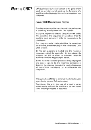
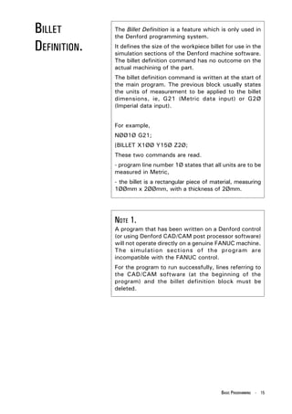
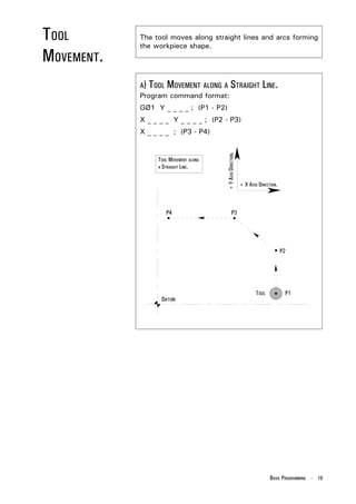
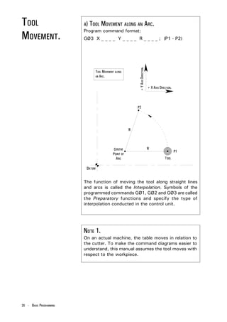
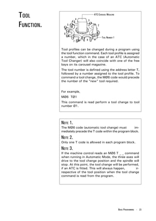
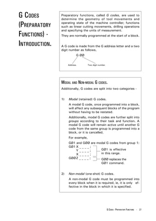
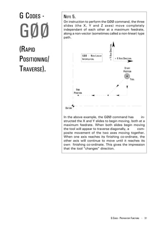
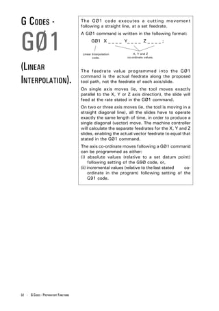
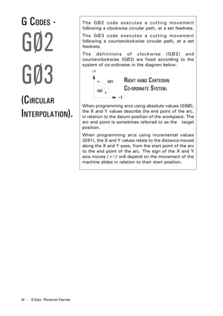
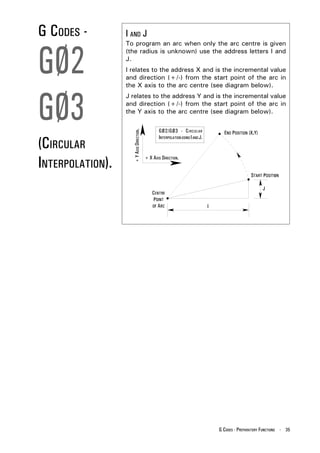
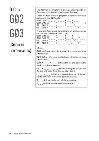
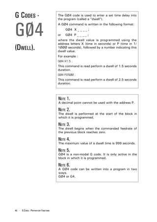
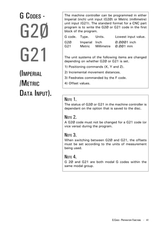
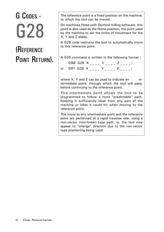
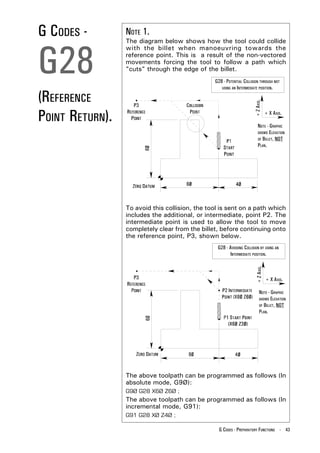
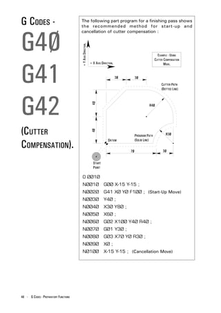
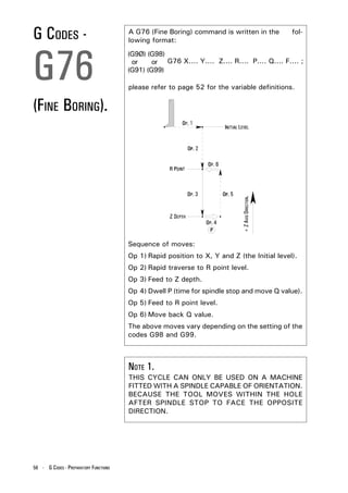
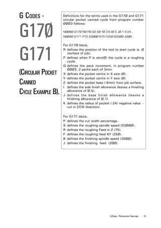
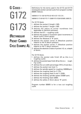
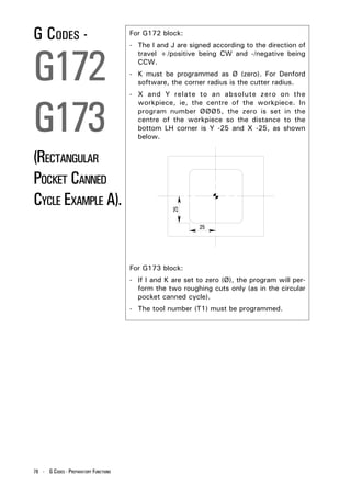
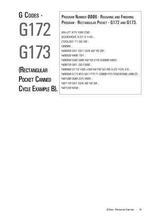
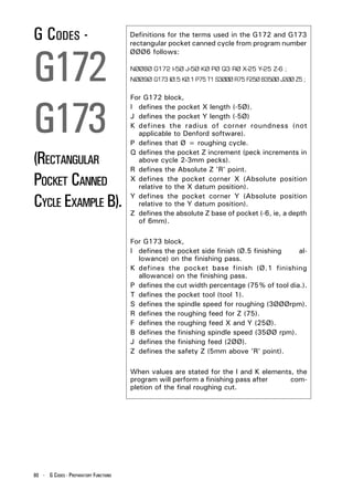
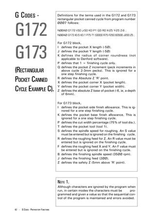
The document discusses the structure and composition of part programs used in computer numerical control (CNC) machining. A part program consists of blocks of coded instructions called G and M codes that describe the machining operations and functions. The main program acts as the controlling program and can call smaller subprograms to perform repeat tasks. Proper organization and ordering of addresses like N, G, X, Y, and Z within each block is important for the CNC machine to interpret the program correctly.