The document provides information on subtractive manufacturing and numerical control processes. It discusses:
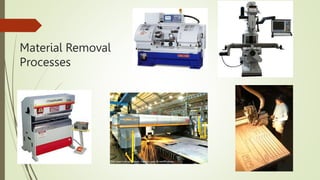
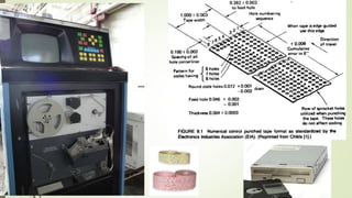
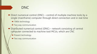
1. Material removal processes and numerical control technology including NC, CNC, and DNC systems.
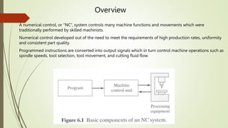
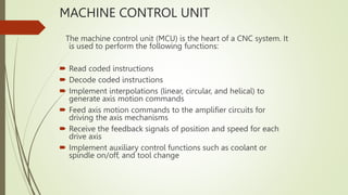
2. The main components of a CNC system including the program input device, machine control unit, and their functions.
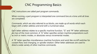
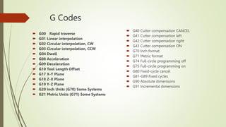
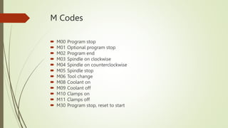
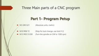
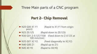
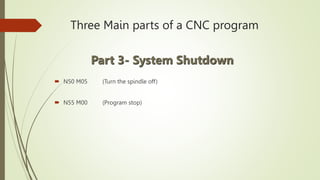
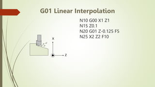
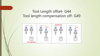
3. CNC programming including different formats, codes like G and M codes, and the basic structure of a CNC program with setup, machining, and shutdown sections.
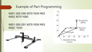
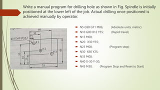
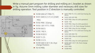
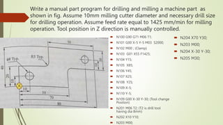
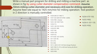
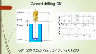
4. Examples of CNC part programs for drilling, milling, and other subtractive operations are provided to illustrate programming concepts.