


![M Codes
M00 (Program Stop):
When the machine controller reads the code M00 within a block, it halts the program
The [CYCLE START] key must be pressed to allow the program to continue
M01 (Optional Stop):
The M01 code performs the same function as the M00 code (program stop), except
the machine controller only recognizes the signal to halt the program if the optional
[STOP] input key is activated
M03 (Spindle Rotation in Clock Wise ):
Clockwise rotation of the spindle
The spindle Rotation command is input stating the program
M04 (Spindle rotation in counter clock wise ):
Counter clockwise rotation of the spindle
The spindle Rotation command is input stating the program
71Prepared by V.S.Bhati & Akash Shukla](https://image.slidesharecdn.com/cnclatheopetatingprogramming-190606084447/85/CNC-Lathe-Operating-Programming-71-320.jpg)


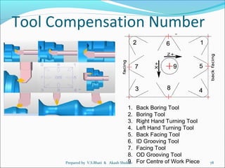


The document provides information about operating and programming CNC lathes. It discusses key parts of CNC lathes like the headstock, tailstock, and turret. It also covers topics like workpiece and tool zero positions, axis nomenclature, common CNC lathe tools, basic operations like turning and threading, and measuring instruments. The document is intended as a guide for CNC lathe operation and programming.