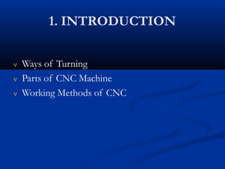
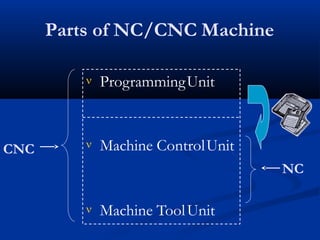
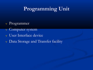
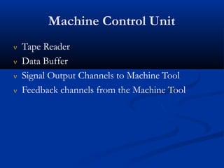
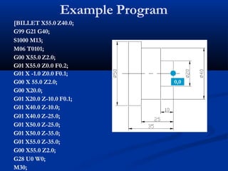
CNC TURNING
Submitted by
Ali Raza
Submitted to
Ali Shan
 INTRODUCTION
 FUNDAMENTAL PRINCIPLES
 INSTRUCTION
1. INTRODUCTION
 Ways of Turning
 Parts of CNC Machine
 Working Methods of CNC
Ways of Turning
 Conventional or Traditional
 Numerical Control (NC)
 Computer Numerical Control (CNC)
Difficulties with Conventional System
 Complex shapes are difficult to machine
 Depends on the human skill
 Frequent & repeated measurements are required
 Difficult to achieve consistency in product quality
 High Changeover Time
 Less productive hours
 More scrap is generated
Parts of NC/CNC Machine
 ProgrammingUnit
 Machine ControlUnit
NC
 Machine ToolUnit
CNC
Programming Unit
 Programmer
 Computer system
 User Interface device
 Data Storage and Transfer facility
Machine Control Unit
 Tape Reader
 Data Buffer
 Signal Output Channels to Machine Tool
 Feedback channels from the Machine Tool
Machine Tool
 Structure
 Extra Rigid
 Easy chip disposal System, eg: Use of Slant Bed
 Thermal Resistant
 Drives
 AC Induction motors
 DC motors
Example Program
[BILLET X55.0 Z40.0;
G99 G21 G40;
S1000 M13;
M06 T0101;
G00 X55.0 Z2.0;
G01 X55.0 Z0.0 F0.2;
G01 X -1.0 Z0.0 F0.1;
G00 X 55.0 Z2.0;
G00 X20.0;
G01 X20.0 Z-10.0 F0.1;
G01 X40.0 Z-10.0;
G01 X40.0 Z-25.0;
G01 X50.0 Z-25.0;
G01 X50.0 Z-35.0;
G01 X55.0 Z-35.0;
G00 X55.0 Z2.0;
G28 U0 W0;
M30;
0,0
Circular Path Function
 G02
 G03
Circular Movement Clockwise (CW)
Circular Movement Counter Clock
Wise (CCW)
Writing Format
G02 X 25.0 Z-10.0 R5.0 F0.1; G03 X 25.0 Z-10.0 R5.0 F0.1;
Types of Instructions
1. Movement Instruction
• G00, G01, G02, G03
2. Machine Instruction
• M00, M02, M03, M04, M05, M06, M08, M09, M30
3. Tool Instruction
• T0101
4. Technological Instruction
•
•
•
Cutting Speed
Spindle Speed
Feed
5. DimensionalInstruction
•
•
Metric
Inch
M-Codes






M00: Program Stop, starts again when cycle start is pressed
M01: Optional Stop
M02: Program Reset
M30: Program Reset & Rewind
M03: Spindle Start in Clockwise Direction
M04: Spindle Start in Anti Clockwise Direction
M05: Spindle Stop
M06: Command Tool Change
M07/M08: Coolant ON
M09: Coolant OFF
M10: Chuck Open
M11: Chuck Close
M13: Spindle ON (CW) & Coolant on
M14: Spindle ON (CCW) & Coolant on
M25: Tailstock Quill Extend
M26: Tailstock Quill Retract
M98: Subprogram Call











 M99: Return to Main Program
Modal & Non Modal G-Codes
 The G-Codes whose effect continue in the
program once specified until it is cancelled or
overridden by another code are known as
“MODAL”. Eg: G00, G01, G02, G03 etc.
 The G-Codes whose effect only in the block where
it is defined are known as Non-Modal Codes. Eg:
G04
https://hanzmanufact
uring.com/
https://www.mnbprecision.com/w
hat-is-cnc-turning/
Thank You

Cnc turning

  • 1.
    CNC TURNING Submitted by AliRaza Submitted to Ali Shan
  • 2.
     INTRODUCTION  FUNDAMENTALPRINCIPLES  INSTRUCTION
  • 3.
    1. INTRODUCTION  Waysof Turning  Parts of CNC Machine  Working Methods of CNC
  • 4.
    Ways of Turning Conventional or Traditional  Numerical Control (NC)  Computer Numerical Control (CNC)
  • 5.
    Difficulties with ConventionalSystem  Complex shapes are difficult to machine  Depends on the human skill  Frequent & repeated measurements are required  Difficult to achieve consistency in product quality  High Changeover Time  Less productive hours  More scrap is generated
  • 6.
    Parts of NC/CNCMachine  ProgrammingUnit  Machine ControlUnit NC  Machine ToolUnit CNC
  • 7.
    Programming Unit  Programmer Computer system  User Interface device  Data Storage and Transfer facility
  • 8.
    Machine Control Unit Tape Reader  Data Buffer  Signal Output Channels to Machine Tool  Feedback channels from the Machine Tool
  • 9.
    Machine Tool  Structure Extra Rigid  Easy chip disposal System, eg: Use of Slant Bed  Thermal Resistant  Drives  AC Induction motors  DC motors
  • 10.
    Example Program [BILLET X55.0Z40.0; G99 G21 G40; S1000 M13; M06 T0101; G00 X55.0 Z2.0; G01 X55.0 Z0.0 F0.2; G01 X -1.0 Z0.0 F0.1; G00 X 55.0 Z2.0; G00 X20.0; G01 X20.0 Z-10.0 F0.1; G01 X40.0 Z-10.0; G01 X40.0 Z-25.0; G01 X50.0 Z-25.0; G01 X50.0 Z-35.0; G01 X55.0 Z-35.0; G00 X55.0 Z2.0; G28 U0 W0; M30; 0,0
  • 11.
    Circular Path Function G02  G03 Circular Movement Clockwise (CW) Circular Movement Counter Clock Wise (CCW) Writing Format G02 X 25.0 Z-10.0 R5.0 F0.1; G03 X 25.0 Z-10.0 R5.0 F0.1;
  • 12.
    Types of Instructions 1.Movement Instruction • G00, G01, G02, G03 2. Machine Instruction • M00, M02, M03, M04, M05, M06, M08, M09, M30 3. Tool Instruction • T0101 4. Technological Instruction • • • Cutting Speed Spindle Speed Feed 5. DimensionalInstruction • • Metric Inch
  • 13.
    M-Codes       M00: Program Stop,starts again when cycle start is pressed M01: Optional Stop M02: Program Reset M30: Program Reset & Rewind M03: Spindle Start in Clockwise Direction M04: Spindle Start in Anti Clockwise Direction M05: Spindle Stop M06: Command Tool Change M07/M08: Coolant ON M09: Coolant OFF M10: Chuck Open M11: Chuck Close M13: Spindle ON (CW) & Coolant on M14: Spindle ON (CCW) & Coolant on M25: Tailstock Quill Extend M26: Tailstock Quill Retract M98: Subprogram Call             M99: Return to Main Program
  • 14.
    Modal & NonModal G-Codes  The G-Codes whose effect continue in the program once specified until it is cancelled or overridden by another code are known as “MODAL”. Eg: G00, G01, G02, G03 etc.  The G-Codes whose effect only in the block where it is defined are known as Non-Modal Codes. Eg: G04
  • 15.
  • 16.