The document provides information about CNC part programming including:
1. It describes common NC words like G-codes, N-codes, and M-codes and their functions in controlling machine tool movement and auxiliary functions.
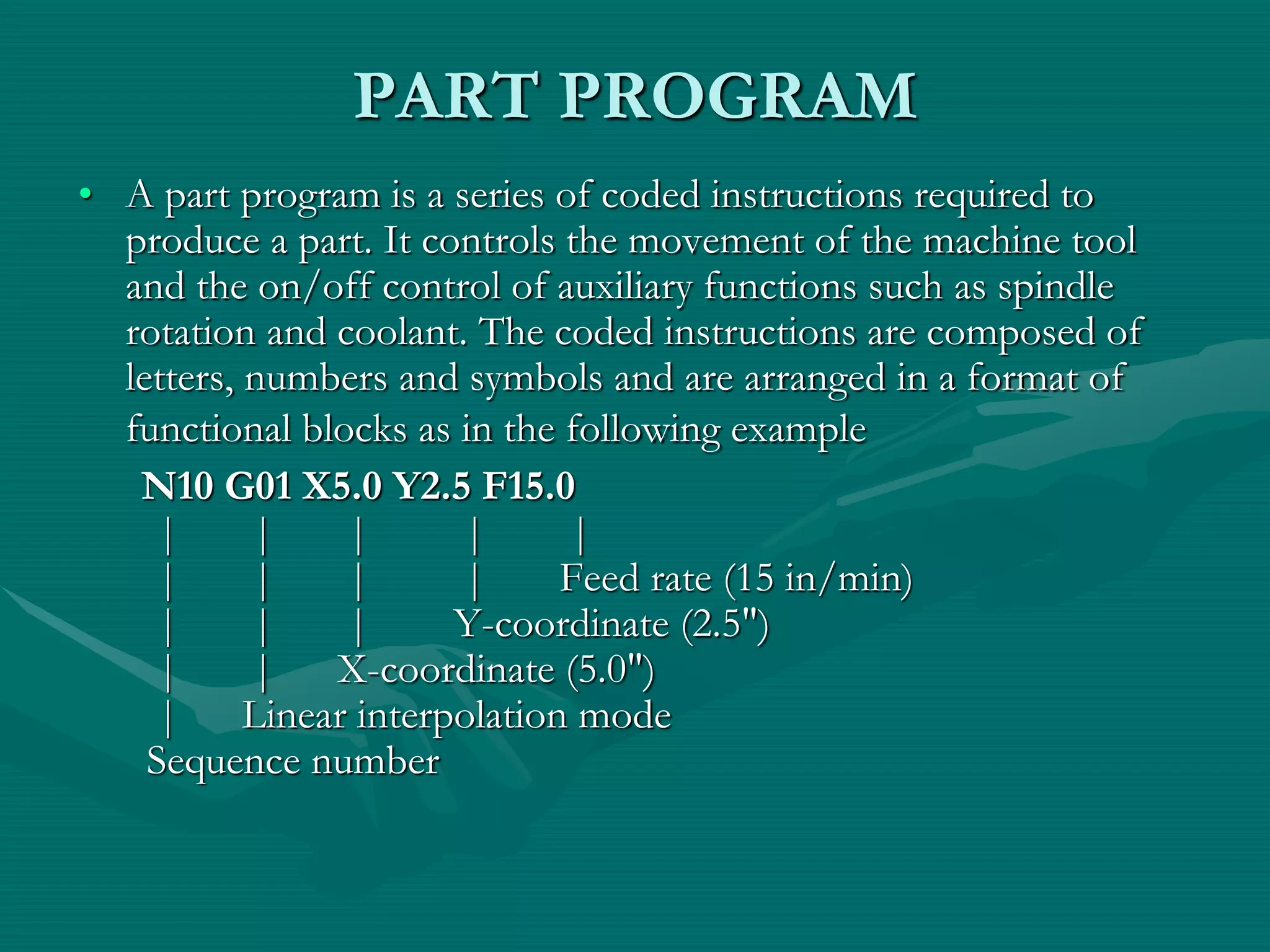
2. It explains the typical structure of a part program including block format, word address coding, and use of codes to specify coordinates, feed rates, spindle speeds, tools, and other information.
3. It provides examples of how codes are used in sample part programs to specify linear and circular interpolation moves, drilling cycles, and other machining operations.
Introduction to CNC machine and Hardware. aman1312
Complete detailing of cnc machine and its operations with its required hardware necessary for increasing its Automation and increasing its manufacturing capability. Also increase in complex shape manufacturing.
Introduction to CNC machine and Hardware. aman1312
Complete detailing of cnc machine and its operations with its required hardware necessary for increasing its Automation and increasing its manufacturing capability. Also increase in complex shape manufacturing.
This describes the mechanism of Computer Numerical Control along with its types, control system, motion system, Programming of CNC, G codes, Part programming, adaptive control machining etc.
Contents:
1. History
2. Introduction to CNC Milling
3. Elements of CNC Machine
4. How CNC Works
5. CNC Programming
6. Advantages and Disadvantages of CNC
7. Applications of CNC
This presentation is prepared as per syllabus of "COMMUNICATION ANALYSIS AND SKILL DEVELOPMENT PROGRAM (CASP)" prescribed by BOARD OF TECHNICAL EDUCATION, KARNATAKA for 5th sem diploma all branches.
This pptx is prepared by lots of information in websites,Textbooks(Author B
A Srinivas and M R Manjunath),And guidance of our lecturers Srinath V- B.E,FIE & M D Dayanand- B.E . SET Polytechnic, Melukote
difference of NC and CNC ,Part programming,Methods of manual part programming,Basic CNC input data,Preparatory Functions ,Miscellaneous Functions,Interpolation:Canned cycles:part programming on component,Tool length compensation,Cutter Radius,Task compensation:Types of media of NC
cnc, mesin cnc, fanuc, haas, makino, yaskawa, doosan, mesin bubut, mesin milling, mesin tapping, wirecut, mesin press, mesin pabrik, mesin otomotif, sparepart mesin cnc
Forklift Classes Overview by Intella PartsIntella Parts
Discover the different forklift classes and their specific applications. Learn how to choose the right forklift for your needs to ensure safety, efficiency, and compliance in your operations.
For more technical information, visit our website https://intellaparts.com
Cosmetic shop management system project report.pdfKamal Acharya
Buying new cosmetic products is difficult. It can even be scary for those who have sensitive skin and are prone to skin trouble. The information needed to alleviate this problem is on the back of each product, but it's thought to interpret those ingredient lists unless you have a background in chemistry.
Instead of buying and hoping for the best, we can use data science to help us predict which products may be good fits for us. It includes various function programs to do the above mentioned tasks.
Data file handling has been effectively used in the program.
The automated cosmetic shop management system should deal with the automation of general workflow and administration process of the shop. The main processes of the system focus on customer's request where the system is able to search the most appropriate products and deliver it to the customers. It should help the employees to quickly identify the list of cosmetic product that have reached the minimum quantity and also keep a track of expired date for each cosmetic product. It should help the employees to find the rack number in which the product is placed.It is also Faster and more efficient way.
Saudi Arabia stands as a titan in the global energy landscape, renowned for its abundant oil and gas resources. It's the largest exporter of petroleum and holds some of the world's most significant reserves. Let's delve into the top 10 oil and gas projects shaping Saudi Arabia's energy future in 2024.
COLLEGE BUS MANAGEMENT SYSTEM PROJECT REPORT.pdfKamal Acharya
The College Bus Management system is completely developed by Visual Basic .NET Version. The application is connect with most secured database language MS SQL Server. The application is develop by using best combination of front-end and back-end languages. The application is totally design like flat user interface. This flat user interface is more attractive user interface in 2017. The application is gives more important to the system functionality. The application is to manage the student’s details, driver’s details, bus details, bus route details, bus fees details and more. The application has only one unit for admin. The admin can manage the entire application. The admin can login into the application by using username and password of the admin. The application is develop for big and small colleges. It is more user friendly for non-computer person. Even they can easily learn how to manage the application within hours. The application is more secure by the admin. The system will give an effective output for the VB.Net and SQL Server given as input to the system. The compiled java program given as input to the system, after scanning the program will generate different reports. The application generates the report for users. The admin can view and download the report of the data. The application deliver the excel format reports. Because, excel formatted reports is very easy to understand the income and expense of the college bus. This application is mainly develop for windows operating system users. In 2017, 73% of people enterprises are using windows operating system. So the application will easily install for all the windows operating system users. The application-developed size is very low. The application consumes very low space in disk. Therefore, the user can allocate very minimum local disk space for this application.
Courier management system project report.pdfKamal Acharya
It is now-a-days very important for the people to send or receive articles like imported furniture, electronic items, gifts, business goods and the like. People depend vastly on different transport systems which mostly use the manual way of receiving and delivering the articles. There is no way to track the articles till they are received and there is no way to let the customer know what happened in transit, once he booked some articles. In such a situation, we need a system which completely computerizes the cargo activities including time to time tracking of the articles sent. This need is fulfilled by Courier Management System software which is online software for the cargo management people that enables them to receive the goods from a source and send them to a required destination and track their status from time to time.
Hybrid optimization of pumped hydro system and solar- Engr. Abdul-Azeez.pdffxintegritypublishin
Advancements in technology unveil a myriad of electrical and electronic breakthroughs geared towards efficiently harnessing limited resources to meet human energy demands. The optimization of hybrid solar PV panels and pumped hydro energy supply systems plays a pivotal role in utilizing natural resources effectively. This initiative not only benefits humanity but also fosters environmental sustainability. The study investigated the design optimization of these hybrid systems, focusing on understanding solar radiation patterns, identifying geographical influences on solar radiation, formulating a mathematical model for system optimization, and determining the optimal configuration of PV panels and pumped hydro storage. Through a comparative analysis approach and eight weeks of data collection, the study addressed key research questions related to solar radiation patterns and optimal system design. The findings highlighted regions with heightened solar radiation levels, showcasing substantial potential for power generation and emphasizing the system's efficiency. Optimizing system design significantly boosted power generation, promoted renewable energy utilization, and enhanced energy storage capacity. The study underscored the benefits of optimizing hybrid solar PV panels and pumped hydro energy supply systems for sustainable energy usage. Optimizing the design of solar PV panels and pumped hydro energy supply systems as examined across diverse climatic conditions in a developing country, not only enhances power generation but also improves the integration of renewable energy sources and boosts energy storage capacities, particularly beneficial for less economically prosperous regions. Additionally, the study provides valuable insights for advancing energy research in economically viable areas. Recommendations included conducting site-specific assessments, utilizing advanced modeling tools, implementing regular maintenance protocols, and enhancing communication among system components.
Democratizing Fuzzing at Scale by Abhishek Aryaabh.arya
Presented at NUS: Fuzzing and Software Security Summer School 2024
This keynote talks about the democratization of fuzzing at scale, highlighting the collaboration between open source communities, academia, and industry to advance the field of fuzzing. It delves into the history of fuzzing, the development of scalable fuzzing platforms, and the empowerment of community-driven research. The talk will further discuss recent advancements leveraging AI/ML and offer insights into the future evolution of the fuzzing landscape.
Quality defects in TMT Bars, Possible causes and Potential Solutions.PrashantGoswami42
Maintaining high-quality standards in the production of TMT bars is crucial for ensuring structural integrity in construction. Addressing common defects through careful monitoring, standardized processes, and advanced technology can significantly improve the quality of TMT bars. Continuous training and adherence to quality control measures will also play a pivotal role in minimizing these defects.
Overview of the fundamental roles in Hydropower generation and the components involved in wider Electrical Engineering.
This paper presents the design and construction of hydroelectric dams from the hydrologist’s survey of the valley before construction, all aspects and involved disciplines, fluid dynamics, structural engineering, generation and mains frequency regulation to the very transmission of power through the network in the United Kingdom.
Author: Robbie Edward Sayers
Collaborators and co editors: Charlie Sims and Connor Healey.
(C) 2024 Robbie E. Sayers
1. TSSM’S
BHIVARABAI SAWANT COLLEGE OF ENGINEERING AND
RESEARCH , POLYTECHNIC, NARHE,PUNE-41
Department Of Mechanical Engineering
Course : Advancedmanufacturingprocess(22563)
Unit 5 : CNC Part Programming
( 16 Marks)
C563.5 : Maintain the functioning of automated equipment..
2. Positions on CNC Machine
Machine Zero (Home Position)
It is also called as home position or machine reference point or grid zero or machine design
Machine zero represents the position of the cutting tool when the tool is at home position
This position is always fixed for a particular machine and is known to the controller. It has not to
be mentioned anywhere in the program as it is already informed to the controller by the
manufacturer
It is the origin of a machine coordinate system.
The position on the machine which is specified by the manufacturer and with respect to which all
other point are defined is called as machine zero
3. • Work piece zero
• It is the position of the cutting tool on the work piece.
• In milling case- it is the south west position
• In Turning case- It is the front face
• This position is specified by the part programmer and may vary for different program
• The entire program is written with respect to the work piece zero position
• The distance between machine zero and work zero is termed as X- offset, Y- offset, Z- offset in
X, Y or Z direction.
4. NC Words
G- Words
N- Words
The different NC words are explained below:
Sequence Number (N- Words)
Preparatory Function (G- Words)
Miscellaneous Function (M- Words)
Co-ordinates (X, Y and Z words)
Feed Function (F- Word)
Spindle Speed Function (S- Word)
Tool Selection Function (T- Word)
8. PART PROGRAM
• A part program is a series of coded instructions required to
produce a part. It controls the movement of the machine tool
and the on/off control of auxiliary functions such as spindle
rotation and coolant. The coded instructions are composed of
letters, numbers and symbols and are arranged in a format of
functional blocks as in the following example
N10 G01 X5.0 Y2.5 F15.0
| | | | |
| | | | Feed rate (15 in/min)
| | | Y-coordinate (2.5")
| | X-coordinate (5.0")
| Linear interpolation mode
Sequence number
10. Steps to write a part program
•Study the given component carefully
•Decide the path to be followed by the cutter.
•Write the co-ordinates of all the points in a separate table
•Then start writing the initial blocks of program.
•The first few blocks are generally same for most of the
programs.
•In the upcoming blocks the tool is moved from the first position
till the last position.
•After the last tool position is machined bring the tool above the
work piece surface.
•Finally the ending blocks are common for all the programs
23. PROGRAM INPUT DEVICE
• The program input device is the mechanism for
part programs to be entered into the CNC
control. The most commonly used program
input devices are keyboards, punched tape
reader, diskette drivers, throgh RS 232 serial
ports and networks.
24. MACHINE CONTROL UNIT
The machine control unit (MCU) is the heart of a CNC system. It
is used to perform the following functions:
• Read coded instructions
• Decode coded instructions
• Implement interpolations (linear, circular, and helical) to generate
axis motion commands
• Feed axis motion commands to the amplifier circuits for driving
the axis mechanisms
• Receive the feedback signals of position and speed for each drive
axis
• Implement auxiliary control functions such as coolant or spindle
on/off, and tool change
25.
26. CNC PROGRAMMING
• Offline programming linked to CAD
programs.
• Conversational programming by the operator.
• MDI ~ Manual Data Input.
• Manual Control using jog buttons or
`electronic handwheel'.
• Word-Address Coding using standard G-codes
and M-codes.
27. The position of the tool is described
by using a Cartesian coordinate
system. If (0,0,0) position can be
described by the operator, then it is
called floating zero.
28. In defining the motion of the tool
from one point to another,
either absolute positioning mode or
incremental positioning mode
can be used.
29. 1. Absolute positioning. In this mode, the
desired target position of the tool for a
particular move is given relative to the origin
point of the program.
2. Incremental positioning. In this mode, the
next target position for the tool is given
relative to the current tool position.
30. Structure of an NC Part Program:
Commands are input into the controller in
units called blocks or statements.
Block Format:
1. Fixed sequential format
2. Tab sequential format
3. Word address format
31. EXAMPLE:
Assume that a drilling operation is to be
programmed as:
1. The tool is positioned at (25.4,12.5,0) by a
rapid movement.
2. The tool is then advanced -10 mm in the z
direction at a feed rate of 500 mm/min., with the
flood coolant on.
3.The is then retracted back 10 mm at the rapid
feed rate, and the coolant is turned off.
33. Modal commands: Commands issued in the
NC program that will stay in effect until it is
changed by some other command, like, feed
rate selection, coolant selection, etc.
Nonmodal commands: Commands that are
effective only when issued and whose effects
are lost for subsequent commands, like, a
dwell command which instructs the tool to
remain in a given configuration for a given
amount of time.
34. INFORMATION NEEDED by a
CNC
1. Preparatory Information: units, incremental or absolute
positioning
2. Coordinates: X,Y,Z, RX,RY,RZ
3. Machining Parameters: Feed rate and spindle speed
4. Coolant Control: On/Off, Flood, Mist
5. Tool Control: Tool and tool parameters
6. Cycle Functions: Type of action required
7. Miscellaneous Control: Spindle on/off, direction of rotation,
stops for part movement
This information is conveyed to the machine through a set
of instructions arranged in a desired sequence – Program.
35. BLOCK FORMAT
Sample Block
N135 G01 X1.0 Y1.0 Z0.125 F5
• Restrictions on CNC blocks
• Each may contain only one tool move
• Each may contain any number of non-tool move G-codes
• Each may contain only one feedrate
• Each may contain only one specified tool or spindle speed
• The block numbers should be sequential
• Both the program start flag and the program number must be
independent of all other commands (on separate lines)
• The data within a block should follow the sequence shown in the
above sample block
36. WORD-ADDRESS CODING
• N5 G90 G20
• N10 M06 T3
• N15 M03 S1250
• N20 G00 X1 Y1
• N25 Z0.1
• N30 G01 Z-0.125 F5
• N35 X3 Y2 F10
• N40 G00 Z1
• N45 X0 Y0
• N50 M05
• N55 M30
Example CNC Program
Each instruction to the machine
consists of a letter followed by a
number.
Each letter is associated with a
specific type of action or piece of
information needed by the machine.
Letters used in Codes
N,G,X,Y,Z,A,B,C,I,J,K,F,S,T,R,M
37. G Codes
• G00 Rapid traverse
• G01 Linear interpolation
• G02 Circular interpolation,
CW
• G03 Circular interpolation,
CCW
• G04 Dwell
• G08 Acceleration
• G09 Deceleration
• G17 X-Y Plane
• G18 Z-X Plane
• G19 Y-Z Plane
• G20 Inch Units (G70)
• G21 Metric Units (G71)
• G40 Cutter compensation –
cancel
• G41 Cutter compensation –
left
• G42 Cutter compensation-
right
• G70 Inch format
• G71 Metric format
• G74 Full-circle programming
off
• G75 Full-circle programming
on
• G80 Fixed-cycle cancel
• G81-G89 Fixed cycles
• G90 Absolute dimensions
• G91 Incremental dimensions
38. M Codes
• M00 Program stop
• M01 Optional program stop
• M02 Program end
• M03 Spindle on clockwise
• M04 Spindle on counterclockwise
• M05 Spindle stop
• M06 Tool change
• M08 Coolant on
• M09 Coolant off
• M10 Clamps on
• M11 Clamps off
• M30 Program stop, reset to start
39. N Codes
• Gives an identifying number for each block of
information.
• It is generally good practice to increment each
block number by 5 or 10 to allow additional
blocks to be inserted if future changes are
required.
40. X,Y, and Z Codes
• X, Y, and Z codes are used to specify the
coordinate axis.
• Number following the code defines the
coordinate at the end of the move relative to an
incremental or absolute reference point.
41. I,J, and K Codes
• I, J, and K codes are used to specify the
coordinate axis when defining the center of a
circle.
• Number following the code defines the
respective coordinate for the center of the circle.
42. F,S, and T Codes
• F-code: used to specify the feed rate
• S-code: used to specify the spindle speed
• T-code: used to specify the tool identification
number associated with the tool to be used in
subsequent operations.
43. Application of Some Codes
G01 Linear Interpolation
Format: N_ G01 X_ Y_ Z_ F_
• Linear Interpolation results in a straight line feed
move.
• Unless tool compensation is used, the
coordinates are associated with the centerline of
the tool.
44. Application of Some Codes
G01 Linear Interpolation
• . As an example, for the motion that occurs in
x-y plane with the same maximum speed for the
x- and y-axis, initial motion is at an angle of 45o
to the axes until motion in one of
• the axes is completed and then the balance of
the motion occurs in the other axis. This is
called point-to-point motion.
45. Application of Some Codes
G01 Linear Interpolation
5
1 0
1 5
2 0
2 5
5 1 0 1 5 2 0 2 5 3 0
A
B C
P o s i t i o n i n g m o t i o n f r o m A t o C
N 1 0 G 0 0 X 3 0 0 0 0 Y 2 0 0 0 0 F 0
46. N10 G00 X1 Z1
N15 Z0.1
N20 G01 Z-0.125 F5
N25 X2 Z2 F10
G01 Linear Interpolation
X
Z
47. G02 Circular Interpolation
• G02 is also a preparatory function to specify
that the tool should be moved to a specified
location along a circular path in a clockwise
direction. In order to specify the path to the
MCU, the end point of the arc and the location
of the center of the arc should be specified.
Within the block in which the G02 code is
programmed, the center of the arc is given by
specifying its location relative to the start of the
arc.
48. G02 Circular Interpolation (CW)
• The G02 command requires
an endpoint and a radius in
order to cut the arc.
• I,J, and K are relative to the
start point.
N_ G02 X2 Y1 I0 J-1 F10
or
N_ G02 X2 Y1 R1
49. G02 Circular Interpolation (CW)
5
1 0
1 5
2 0
2 5
5 1 0 1 5 2 0 2 5 3 0
C
C
C i r c u l a r i n t e r p o l a t i o n f r o m A t o B
a b o u t a c i r c l e c e n t e r e d a t C
N 1 0 G 0 2 X 2 0 0 0 0 Y 1 0 0 0 0
I 5 0 0 0 J 1 5 0 0 0 F 2 5 0 0
A
B
I = 5
J = 1 5
50. The sequence of some machining operations is may be
the same for any part and for any machine. For example,
drilling a hole involves the following steps:
Position the tool above the point where the hole will be
drilled
Set the correct spindle speed
Feed the tool into the workpiece at a controlled feed rate
to a predetermined depth
Retract the tool at a rapid rate to just above the point
where the hole started
Canned Cycles
51. Some Commonly Used Canned Cycle
Code Function Down feed At bottom Retracti
on
G81 Drilling Continuous
feed
No action Rapid
G82 Spot face,
counterbore
Continuous
feed
Dwell Rapid
G83 Deep hole drilling Peck No action Rapid
G84 Tapping Continuous
feed
Reverse
spindle
Feed
rate
G85 Through boring(in
& out)
Continuous
feed
No action Feed
rate
G86 Through boring(in
only)
Continuous
feed
Stop
spindle
Rapid
53. Three Main parts of a CNC program
• N5 G90 G21 (Absolute units, metric)
• N10 M06 T2 (Stop for tool change, use
tool # 2)
• N15 M03 S1200 (Turn the spindle on CW
to 1200 rpm)
Part 1- Program Petup
54. Three Main parts of a CNC program
• N20 G00 X1 Y1 (Rapid to X1,Y1 from origin
point)
• N25 Z0.125 (Rapid down to Z0.125)
• N30 G01 Z-0.125 F100 (Feed down to Z-0.125 at
100 mm/min)
• N35 G01 X2 Y2 (Feed diagonally to X2,Y2)
• N40 G00 Z1 (Rapid up to Z1)
• N45 X0 Y0 (Rapid to X0,Y0)
Part 2- Chip Removal
55. Three Main parts of a CNC program
• N50 M05 (Turn the spindle off)
• N55 M00 (Program stop)
Part 3- System Shutdown
57. G-CODE PROGRAM
• First pass : conventional mill to a
depth of 0.125 around edge profile.
Tool 1 is a ½ inch dia. end mill.
%
:1002
N5 G90 G20
N10 M06 T1
N15 M03 S1200
N20 G00 X0.125 Y0.125
N30 Z0.125
N35 G01 Z-0.125 F5
N40 X3.875
N45 Y4.125
N50 X0.125
N55 Y0.125
58. • Second pass:
conventional mill to a
depth of 0.25 around
edge profile.
N35 Z-0.250
N40 X3.875
N45 Y4.125
N50 X0.125
N55 Y0.125
N60 Z0.125
59. • Third pass: conventional
mill to a depth of 0.125
around pocket profile.
N65 G00 X1.25 Y1.0
N70 G01 Z-0.125 F5
N75 X1.75
N80 Y2.5
N85 X1.25
N90 Y1.0
N95 Z0.125
60. • Fourth pass: climb mill
to a depth of 0.125
across remaining
material.
N100 Y2.125
N105 X2.625
N110 Z0.125
N115 G00 X-5 Y-5 Z5
N120 M05
N125 M30
61. Advanced features:
• Execution of the part of the program in a rotated
or mirrored position.
• Ability to scale the program and produce larger or
smaller programs.
• Three dimensional circular interpolation which
produces a helical shape.
• Parabolic and cubic interpolation.
62. • NC program preparation may be tedious and difficult
if the part to be machined has a complex geometry.
The main difficulty is to find out the cutter locations
during the machining. Computers may be used to
assist the programmers in preparing the NC codes.
Computer Aided Part Programming:
63. Advantages of applying computer-aided part
programming include the following:
• 1. It reduces the manual calculations involves in
determining the geometric characteristics of the part.
• It provides the cutter path simulation.
• It provides tool collision checking.
• It shortens the program preparation time.
• It makes the program preparation easier.
64. • The Aerospace Industries Association sponsored the
work that led to the first part programming language,
developed in MIT in 1955.
• This was called: Automatically Programmed Tools (APT).
• APT is an English like simple programming language
which basically produce the Cutter Location (CL) data.
• Using the cutter location data, the program can
generate the actual NC codes by using a
postprocessor .
65. • The output of any CAD package include the
geometric data of the part to be machined. Therefore,
many CAD/CAM package can produce cutter
location (CL) data to be used for NC code generation.
• There is still to be a process planning module for a
workable NC code generation.
• Some of the CAD/CAM packages that have the NC
code generation capabilities are Computervision,
CATIA, CADAM, ProEngineer, MechanicalDesktop
(Auto Desk).
CAD/CAM Based Part Programming:
66. CNC Prg. Basics 66
CNC Programming Basics
Program structure
Every program consists of:
1. Program Start
The program start is the program number. The program number begins
with character/letter O.
2. Program Contents
NC blocks
3. Program End
M30 for a main program
M17 for a sub-program
67. CNC Prg. Basics 67
CNC Program Numbers
Program Numbers
O6999
.
.
.
O0256
O0255
.
.
.
O0000
68. CNC Prg. Basics 68
CNC Program Blocks (1)
• N is the address
• Block numbers from N0000 to
• N9999
• A block consists of number and words
• Words are contents of a block
• Block numbers are selected in the jumps of
ten for the purpose of insertion
69. CNC Prg. Basics 69
CNC Program Blocks (2)
• A block consists of one or more blocks
• A Word consists of a character (address)
and a number.
• Every address has a certain meaning, on
which the corresponding number depends
70. CNC Prg. Basics 70
CNC Prg. Syntax Regulations
• The maximum block length must not exceeded four lines. If max. length exceeded
alarm 650 occurs.
• Every block starts with a block number.
• After the block numbers follows the G command.
• Words consists of coordinates X(U), Z(W).
• For G02, G03 program interpolation parameter I and K are placed after X(U),
Z(W).
• The F word (feed, thread pitch).
• The S word (cutting speed).
• The T word (tool address).
• The M word (additional functions).
74. CNC Prg. Basics 74
Self-holding Functions (1)
• The majority of G and M commands and other words are self-holding,
remain active until overwritten or deactivated/deselected.
• Aimed to simplify and to reduce programming tasks.
Example: G41 can be deactivated by issuing G40 command.
75. CNC Prg. Basics 75
Self-holding Functions (2)
Take-over of G00 commands in block N0110
In block N0120 G00 is deactivated by G01. G01 is active.
N0100 G00 X50. Z+10.
N0110 X36. Z+2.
N0120 G01 X40. Z-10. F…
N0050 M03
N0060 …
…
N0120 M04
Example 1:
Example 2:
M03 activated at N0050 and effective
from N0050 through N120. M03
deactivated at N0120 by M04 command
76. CNC Prg. Basics 76
Reference Points
M = Machine zero point.
(unchangeable ref. Point determined
by machine manufacturer)
N = Tool mounting reference point
W = Work piece zero point. (can be
freely determined by the programmer
and can be moved within program
79. CNC Prg. Basics 79
G & M Commands
G00: Rapid traverse
G01: Linear interpolation
G02: Circular interpolation clockwise
G03: Circular interpolation counter clockwise
G70: Measuring in Inch (USA)
G71: Measuring in mm (Other countries)
M03: Spindle ON clockwise
M04: Spindle ON counter clockwise
M20: Tailstock back
M21: Tailstock forward
80. CNC Prg. Basics 80
G00, Rapid Traverse
Absolute dimensions of the target point
coordinates:
N030 G90
N040 G00 X48 Z-26
An absolute X coordinate related to
the diameter.
Incremental dimensions of the target point
coordinates:
N030 G91
N040 G00 X-10,5 Z-31
Tool position X69 Z5
82. CNC Prg. Basics 82
G90 & G91 Commands
G90
G01 X+140 Z-90
Target point abs.
G91
G01 X+40 Z-60
Target point incr.
PO: Start Point
P1: Target Point
For more detail contact us