Downloaded 64 times


![CNC-Operation (Survey)
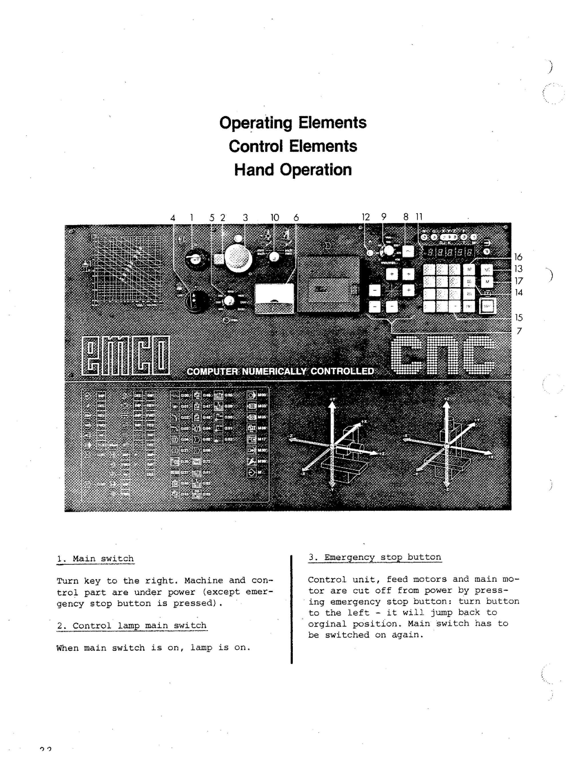
5. Switch for main spindle
11. Keys for program input, correction,
storing of program on tape, V24
operation etc. (see detailed explanations)
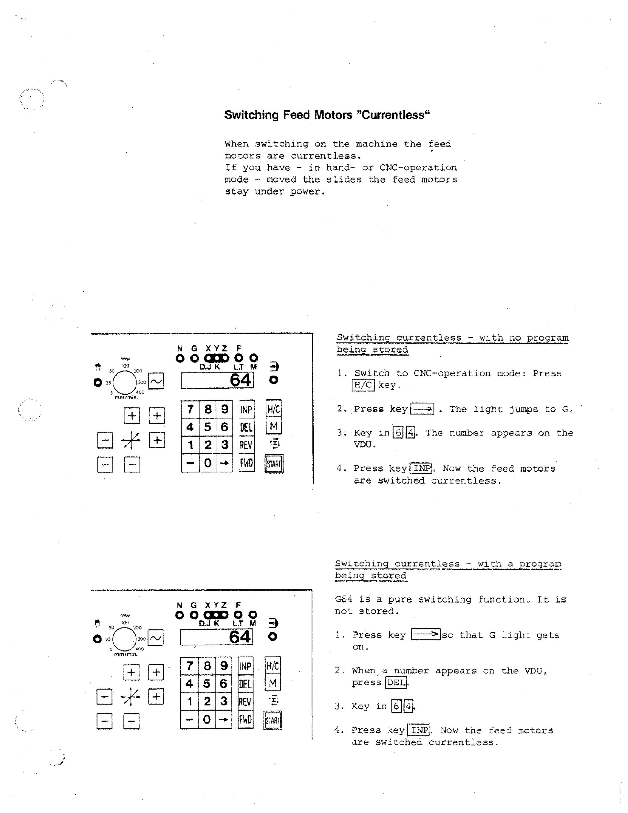
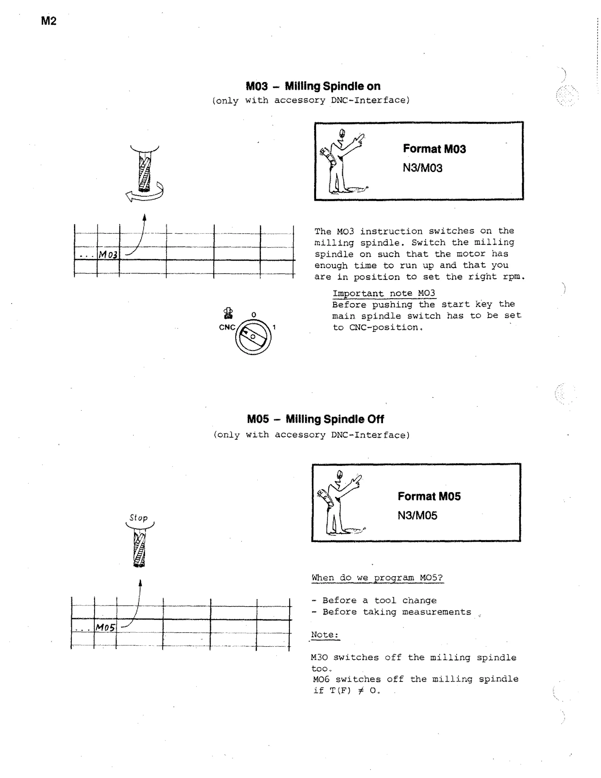
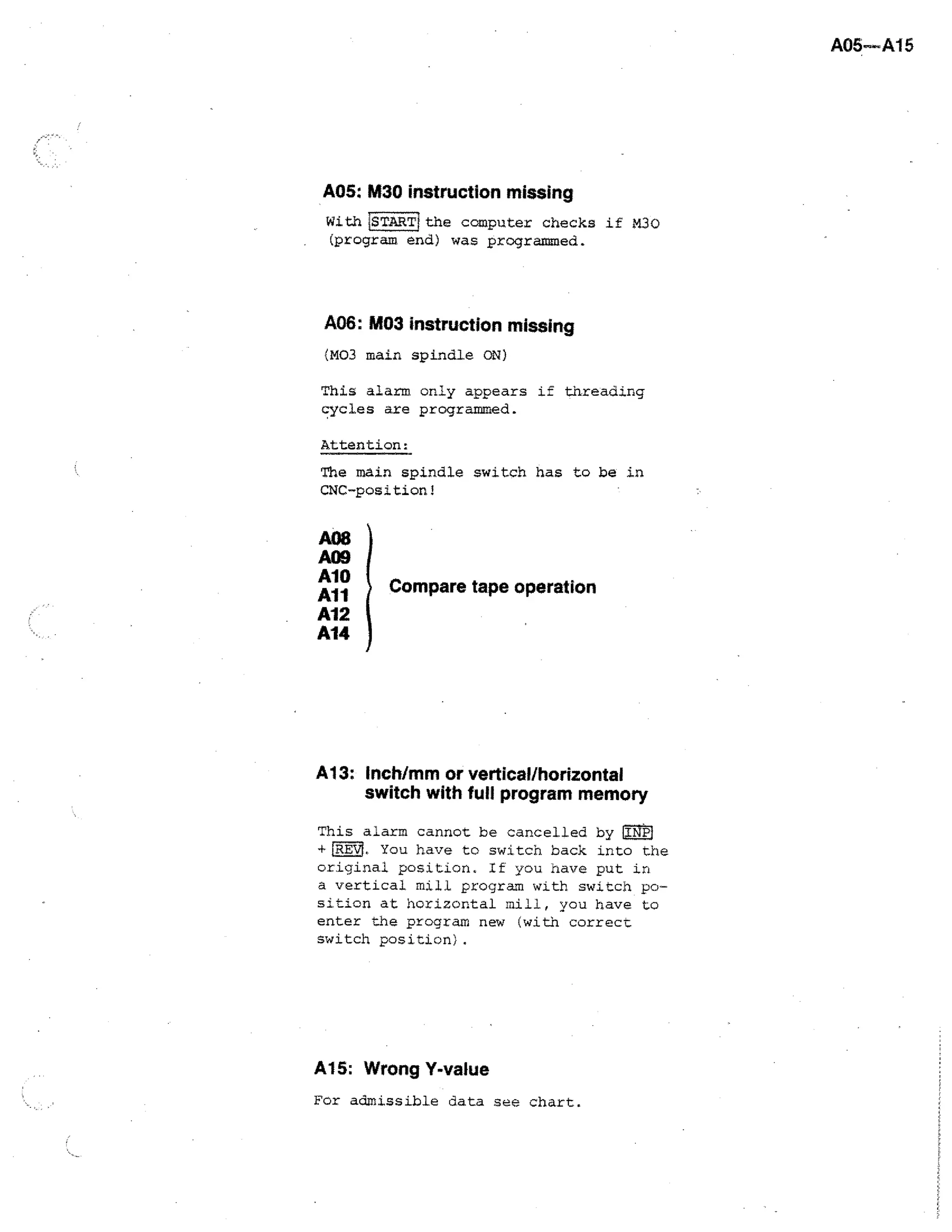
Position 1 (main spindle ON, without M03)
Position CNC: main spindle is
switched on by programming M03 and
switched off by M05, M06 (with F*0)
and M30.
6. Ammeter
7. Magnetic tape
switch key
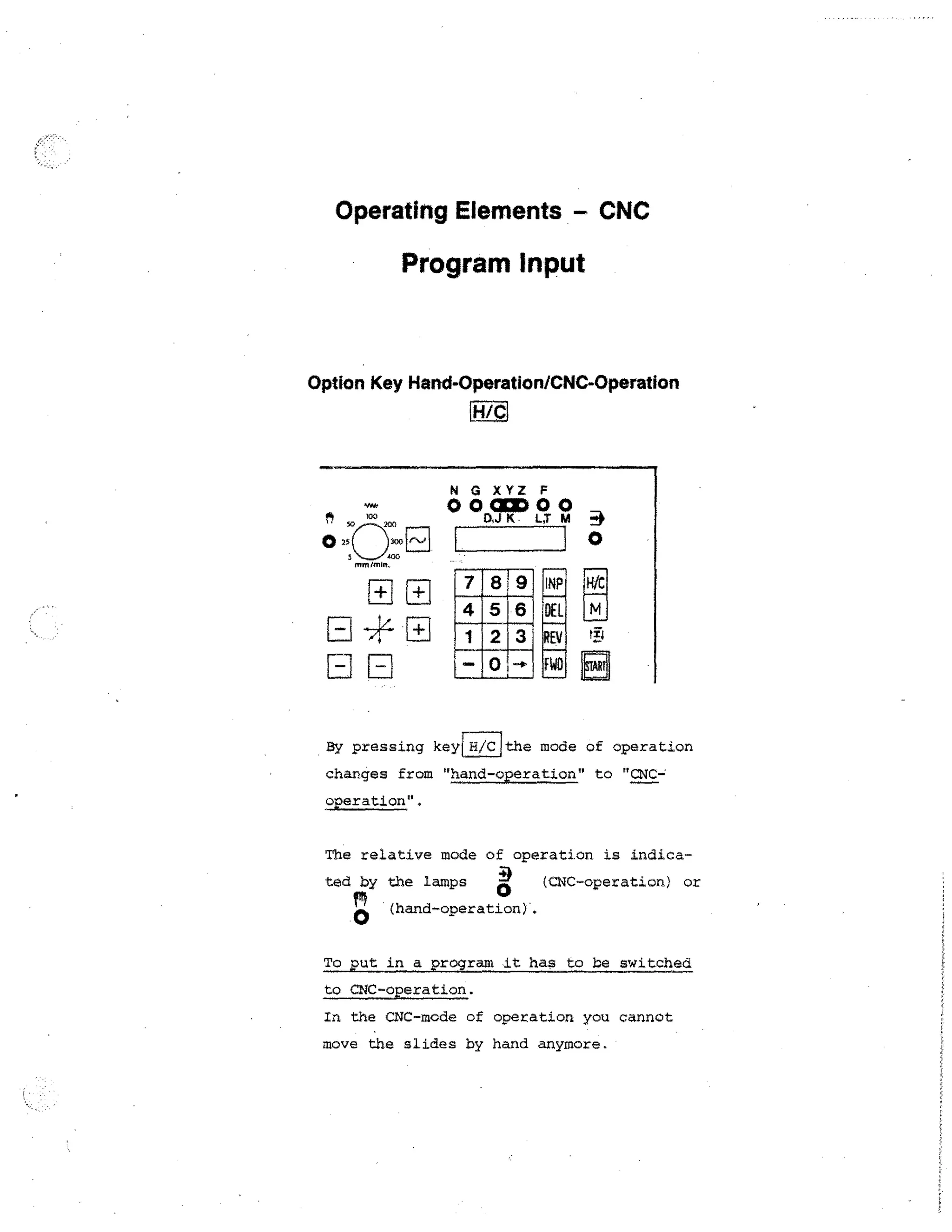
Manual/CNC operation
9. Control lamp CNC operation
10.1-HAW-IT-key
The program is being worked off
11.1. Number keys 0 -1791
I1.2..7 The minus sign key
-7
To enter minus values the minus
sign E] has to be pressed after
input of numbers.
11.3. INP1 key (INPUT = storing)
Storing key
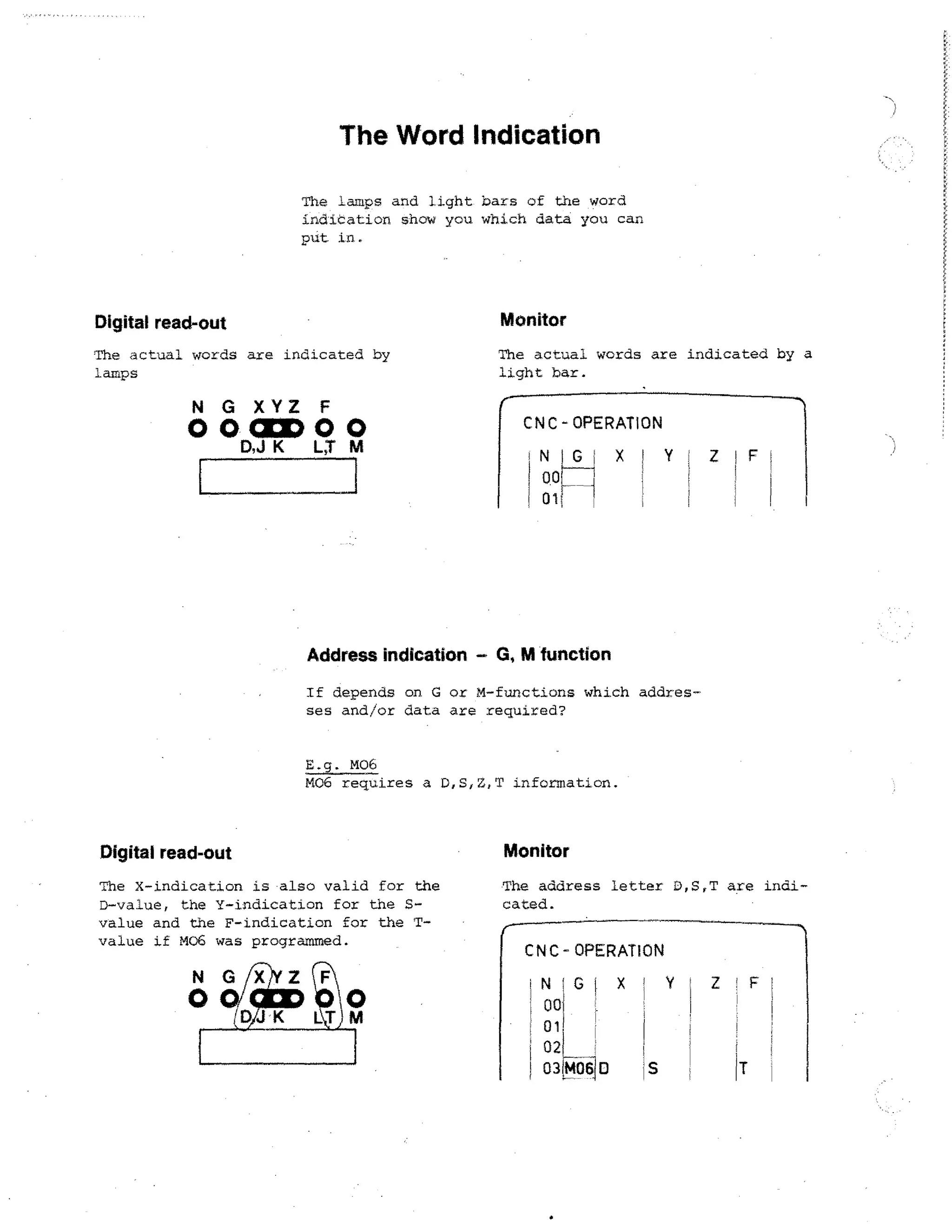
12. VDU (display)7
Indicates values for address letters
and modes of operation
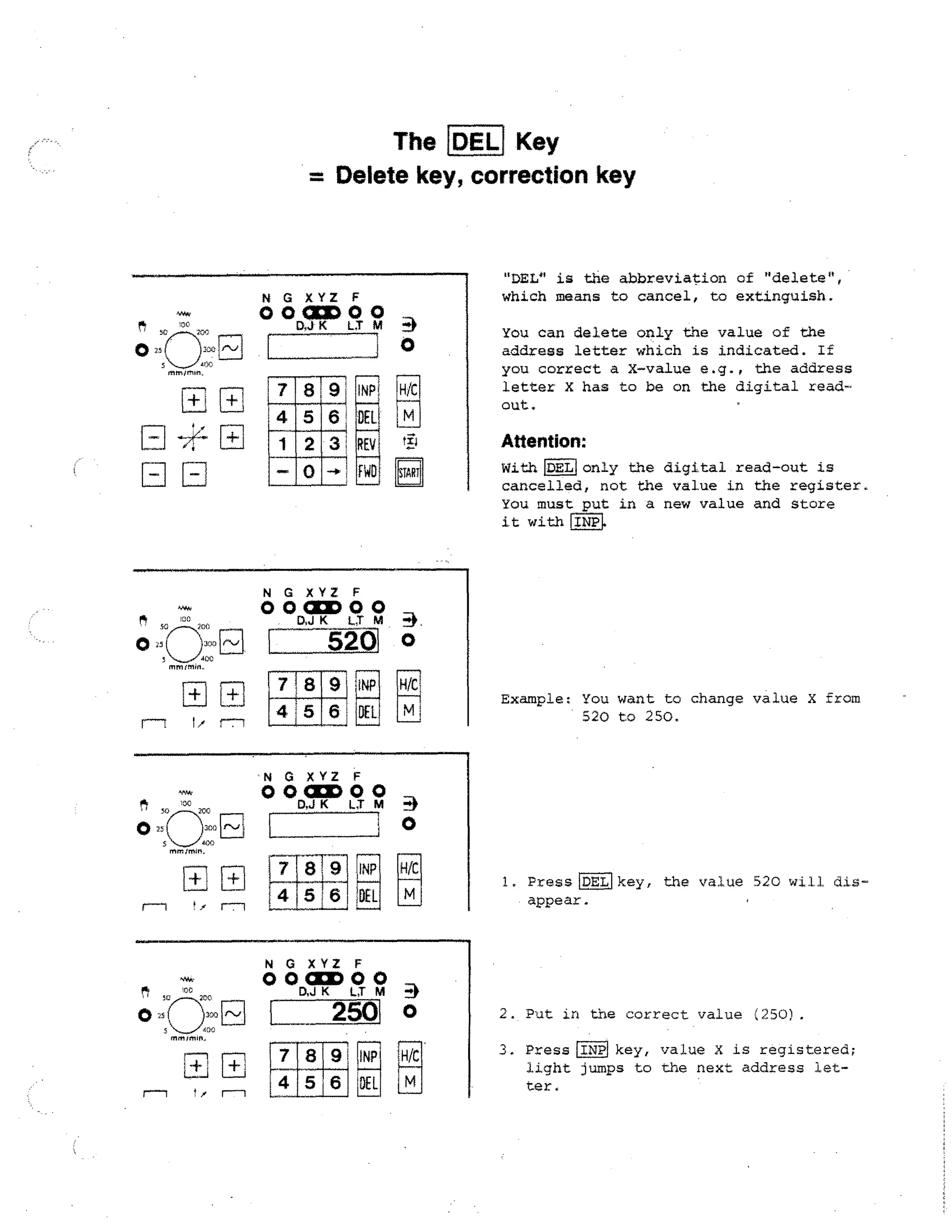
11.4.1DEL1 key (DELETE = erase)
Erasing key
13. Control lamp address letters
11.5.1FWD1 key (FORWARD)
Program jumps forward block by
block
14. Control of milling spindle speed
11 .6 .
key (REVERSE)
Program jumps backwards block by
block
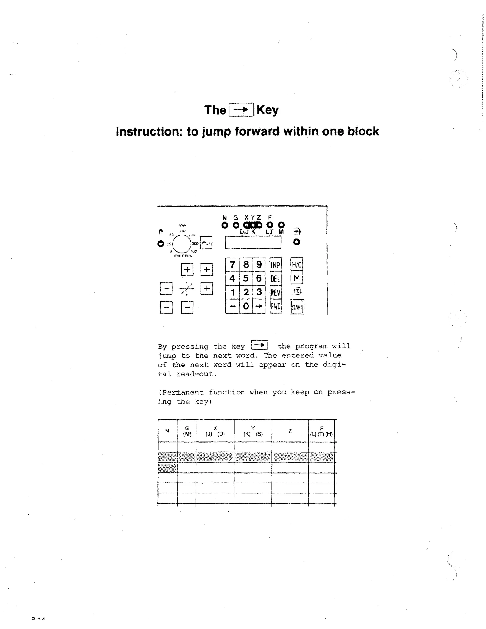
11.7. H.] Arrow•key
Display jumps word by word
11.8, ld key: key for entering of miscellaneous functions.](https://image.slidesharecdn.com/pemrogramancnctu-3a-140220040523-phpapp02/75/Pemrograman-cnc-tu-3-a-30-2048.jpg)
![CNC-Operation (Survey)
Operation CNC
LINPI Storing of word contents
[DEL Deleting of word contents
FWD.] Forward in program block by block
GREVI
Backward in program block by block
HI1, 1
Forward in block word by word
lM
Input of M-functions
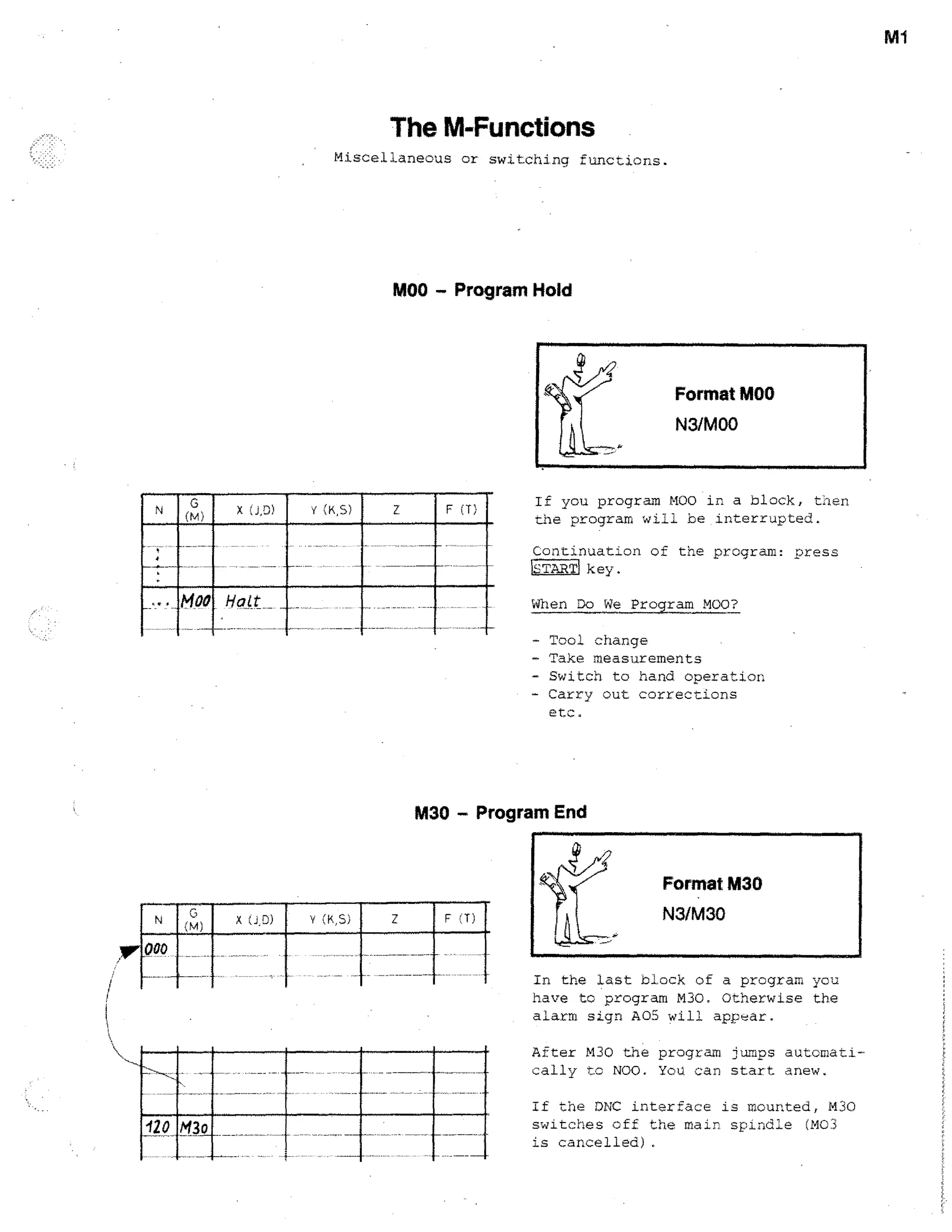
Program hold:
FWD]
1INP
Program interruption
LINP
RE vj
Delete program
LDELi+ INP ]
First DEL; then INPi
Operation — Magnetic tape
Storing of program on tape
G65
Fiicril --
number —
FWD
I INPj
Put in program
r--7
LDELIremains pressed.
Delete alarm
REV!
INP1
Insert block
ry
fi
IINP
Transmit program from tape to memory
Select program
G65INP
number --b. iINP1
Delete tape contents
G65
Delete block
+DEId
Single block mode
T
3
etc. +1STARTI
Testrun:
1M
1
+](https://image.slidesharecdn.com/pemrogramancnctu-3a-140220040523-phpapp02/75/Pemrograman-cnc-tu-3-a-35-2048.jpg)
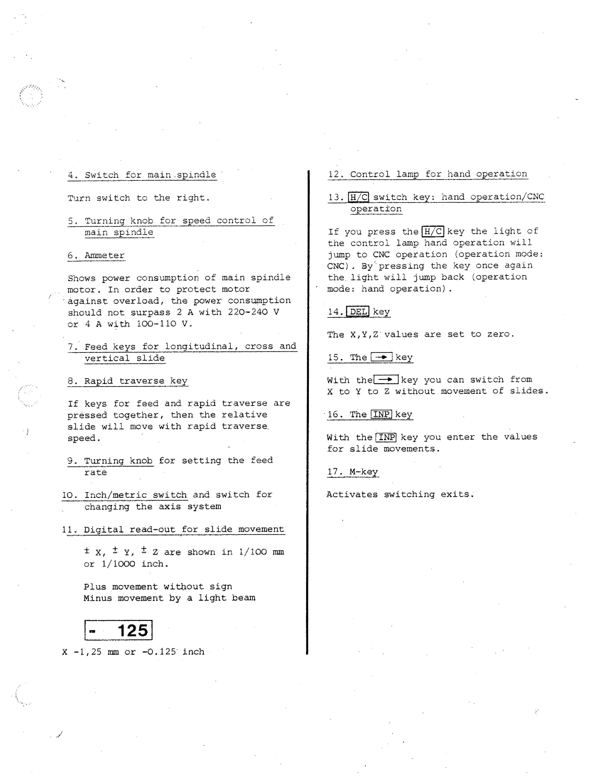
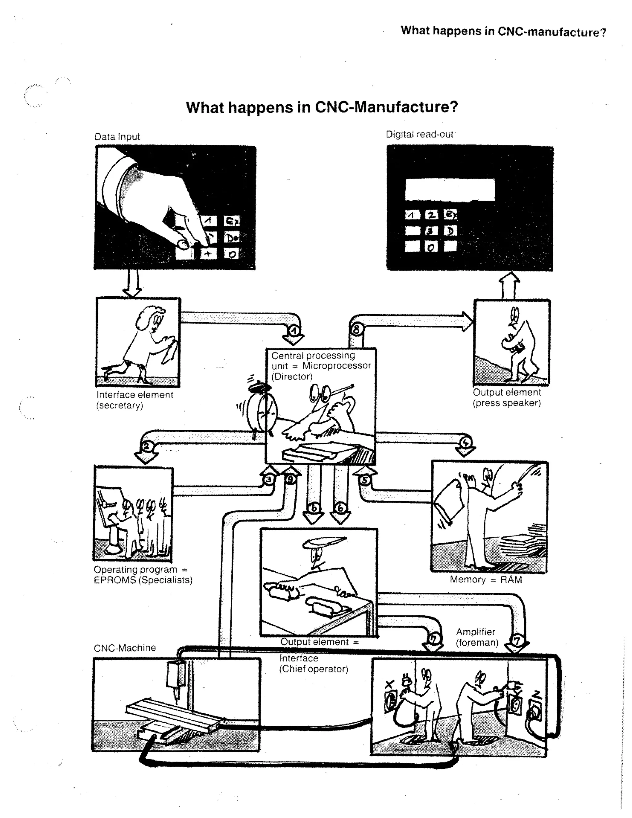
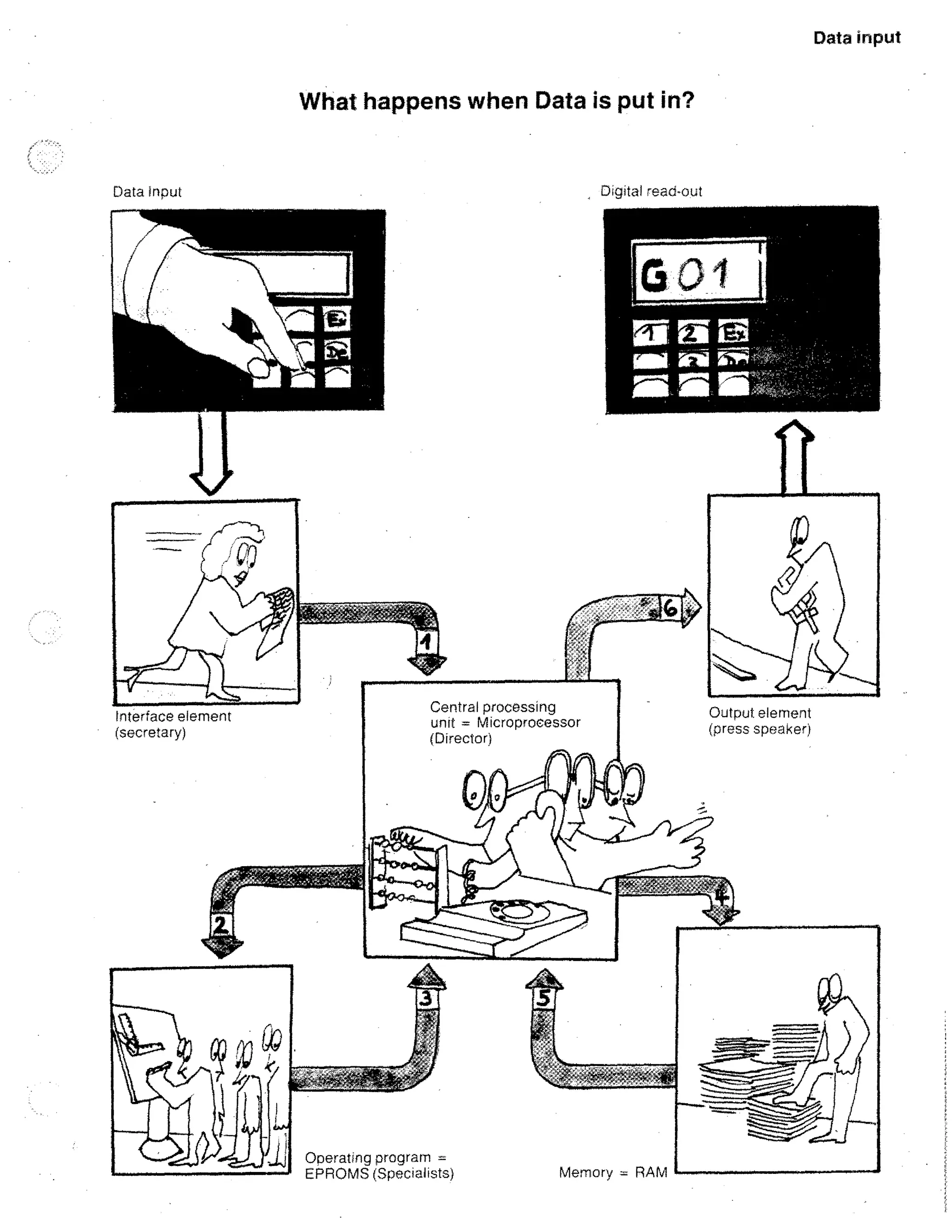
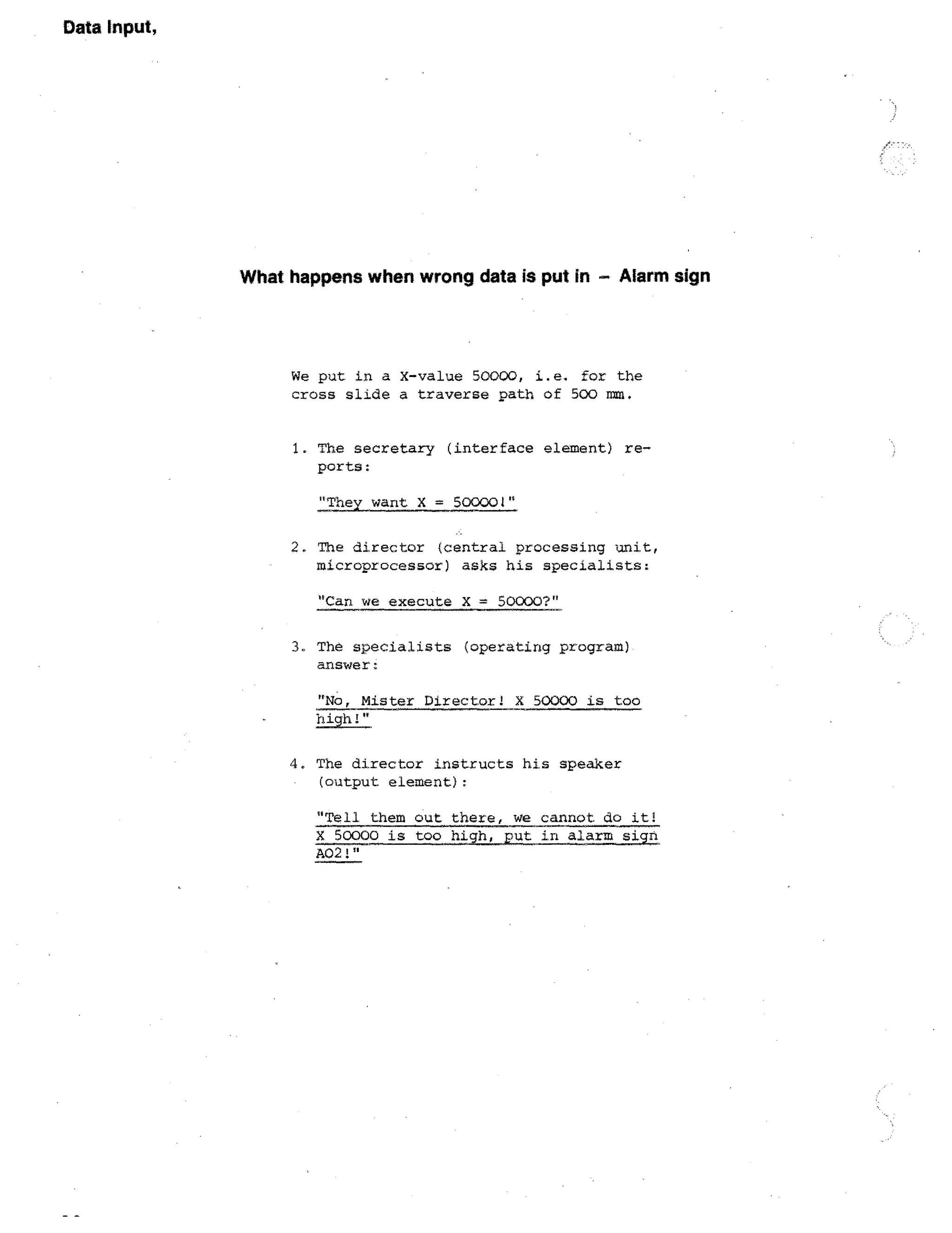
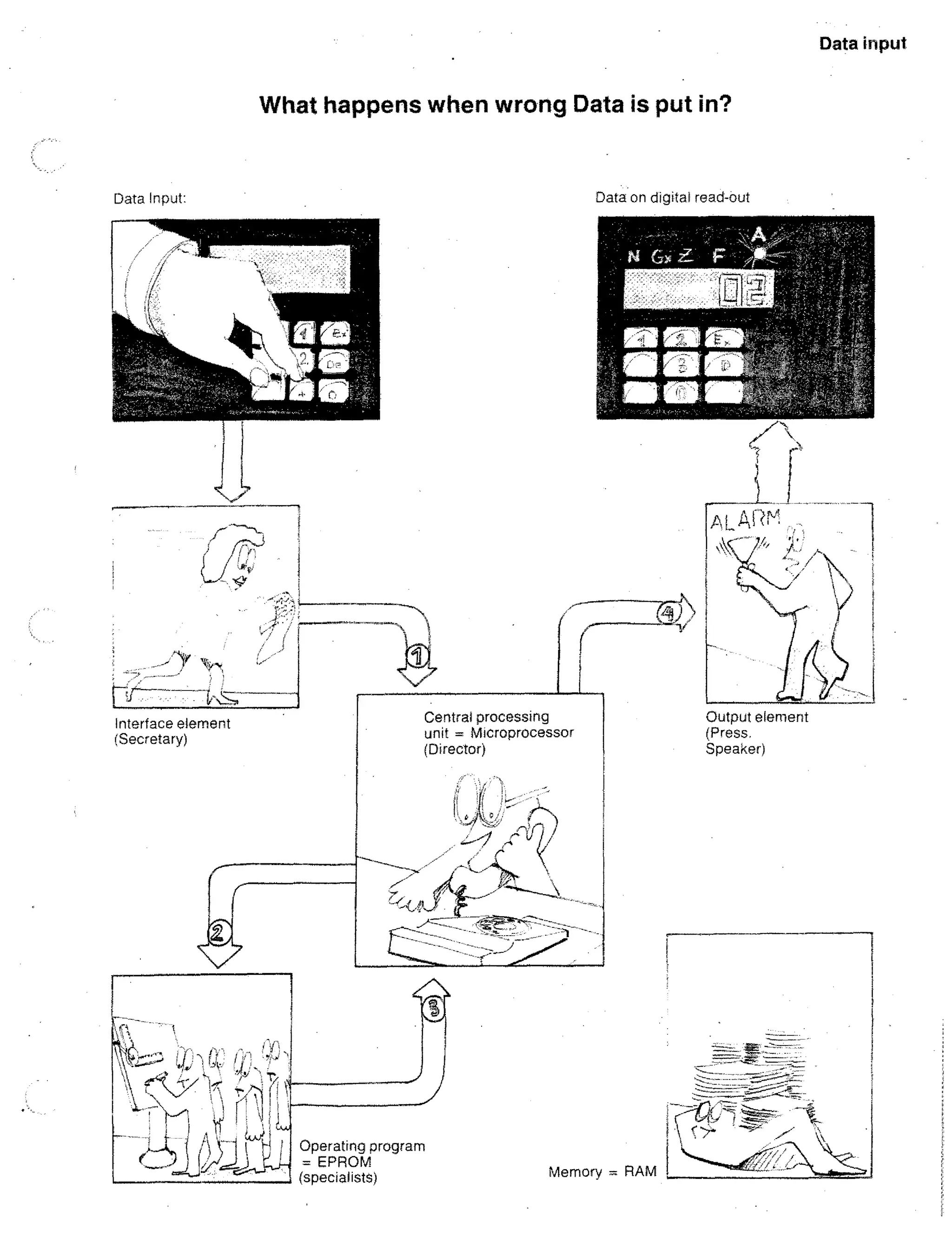
![What happens in CNC-Manufacture
3. specialist ---4■Director:
,Data input
"Yes, o.k."
I Data processing / Data storing]
4. Director ----opMempry:
"Please give me the data!"
5. Memory
Data outputj
–lb-Director:
X,Y slides have to be moved in ratio
1 : 4.
In the computer nothing happens without
the director. There is a strict
hierarchy.
What
happens
1. Secretary
if you press the key START?
6. Director calculates and gives data
to chief operator. With the aid of
the watch he also determines the operating speed (when threading he
waits for the main spindle position).
1.Director:
"They pressed START!"
Director asks memory:
"Did they put in program end M30?"
7. Chief op erator ----III-Foreman:
Move X slide with feed size F1 and
Y slide with feed size F2.
If yes, the program can start.
2. Director ----ipSpecialists:
We want to machine a groove in a
certain angle.
4.4
8. Director ----Ili-Press speaker:
"The block is finished. We work on the
next. Let them know!"](https://image.slidesharecdn.com/pemrogramancnctu-3a-140220040523-phpapp02/75/Pemrograman-cnc-tu-3-a-41-2048.jpg)
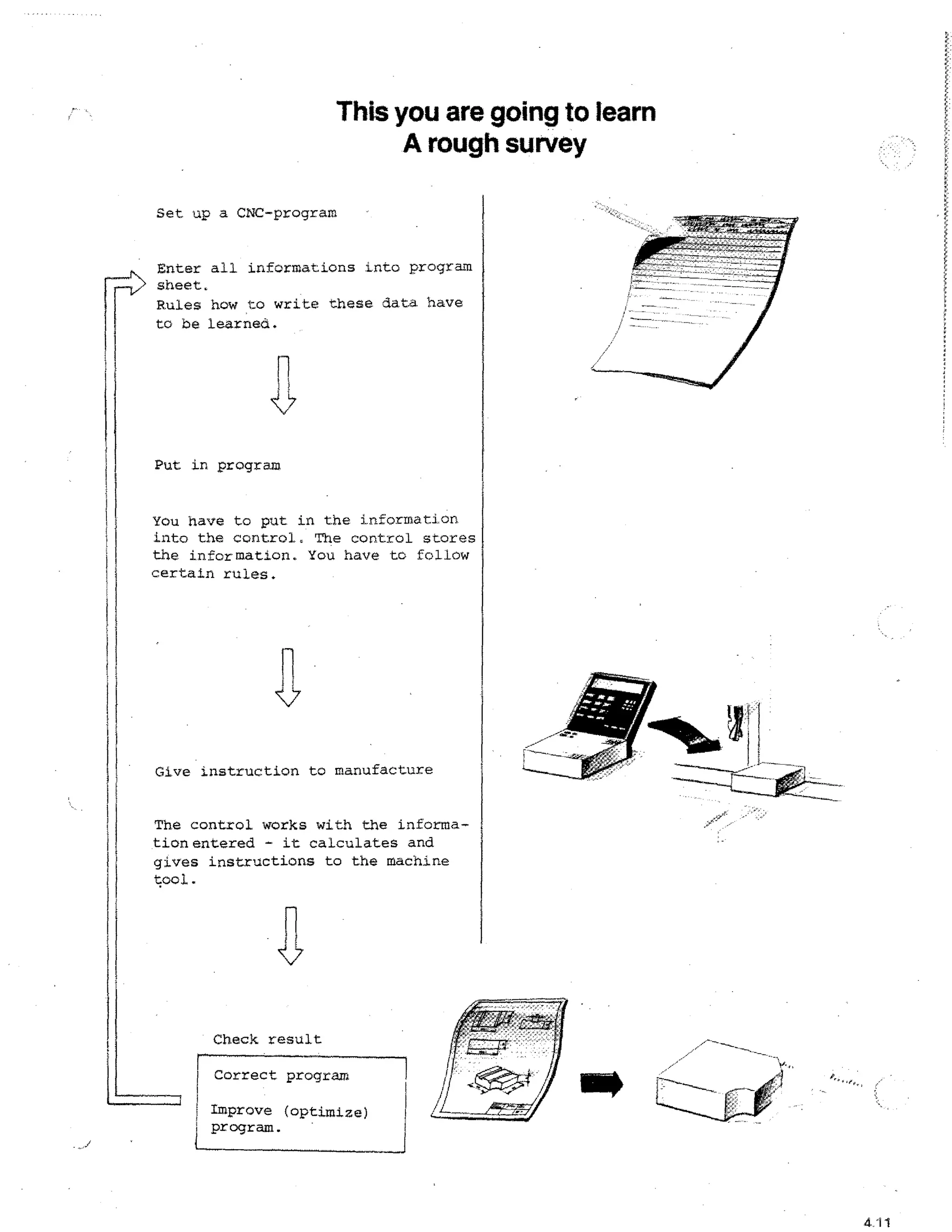


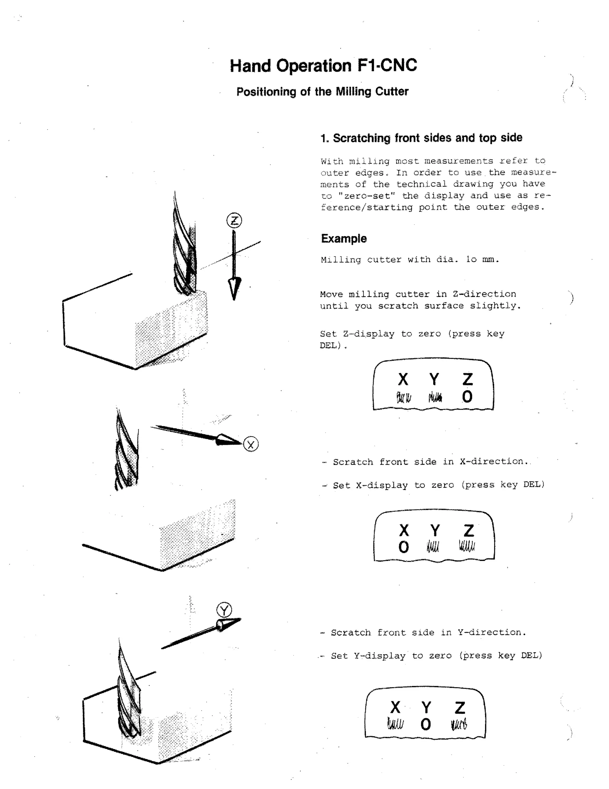
![S u ry e y
Data Input, Correction, Delete
Storing a word
Sequence of Program
Testrun:
Inching through the program
FITTj
Take over of values
Single block operation
Correcting a word
Put in
P24]-4.
v alue
7
+
••--•
M-programming
(first number key)
Press g
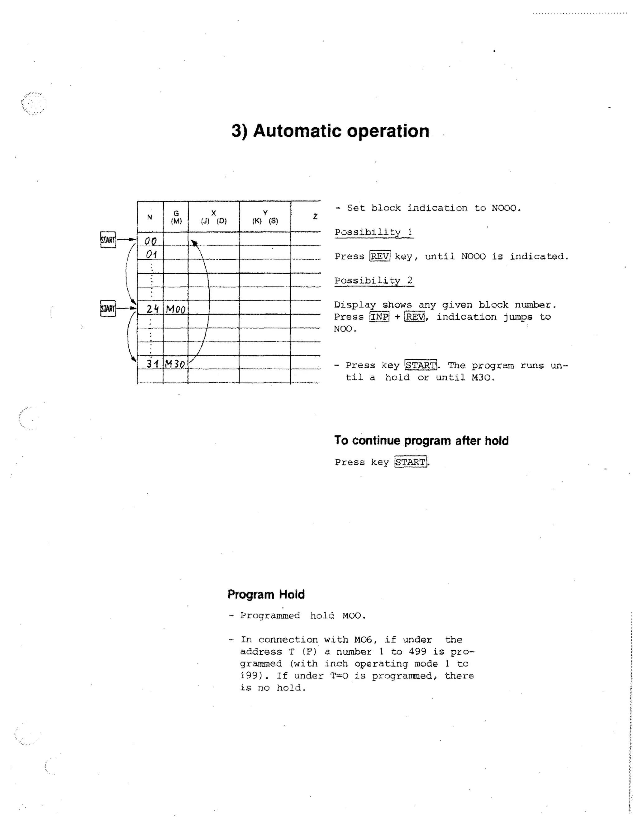
Automatic operation
Searching
a word
Searching a block
FWD
iSTAR1
Influencing the Program
riR8C71
Inserting a block
;Aal + riNiq
Deleting a block
+
;DEL]
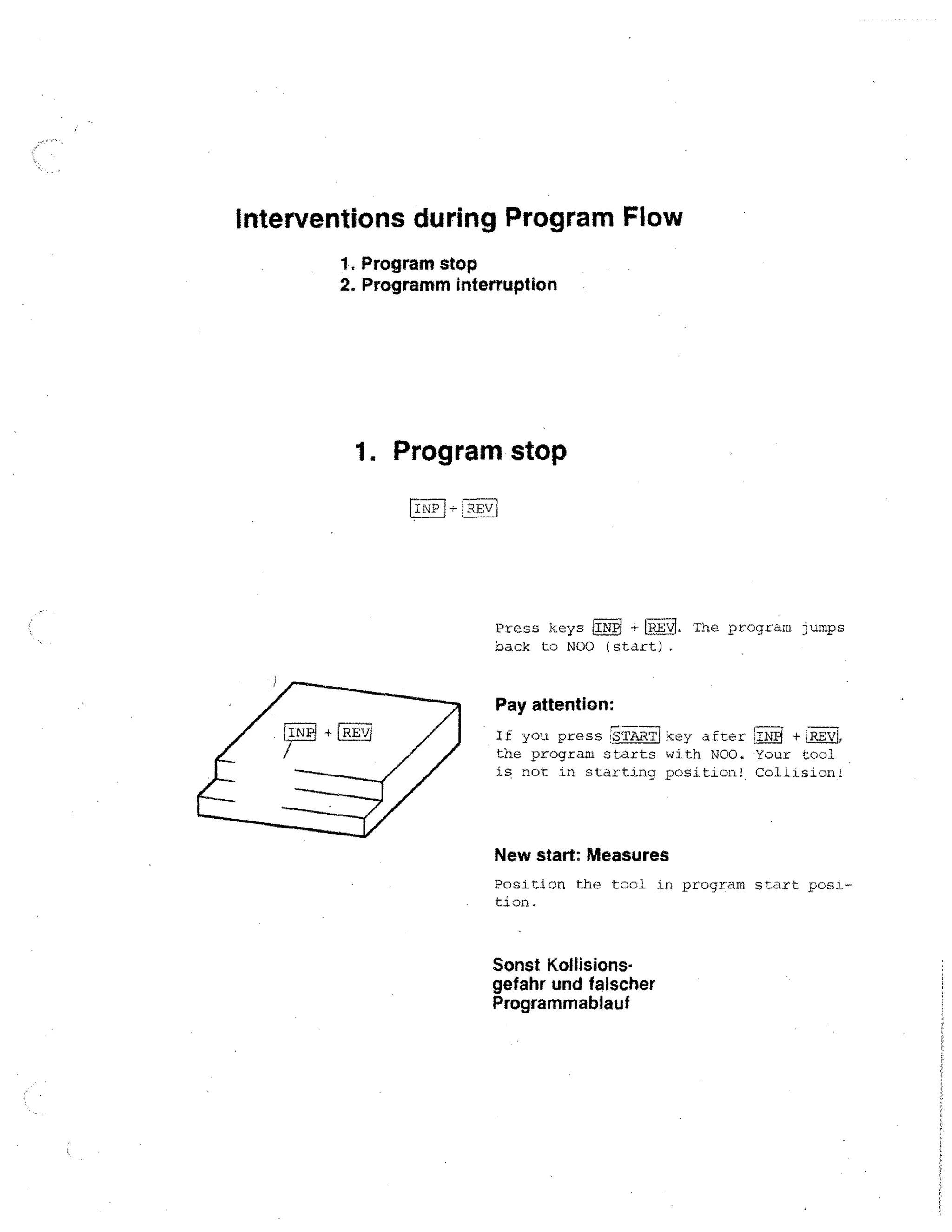
Termination
[INP1 +IRE
A
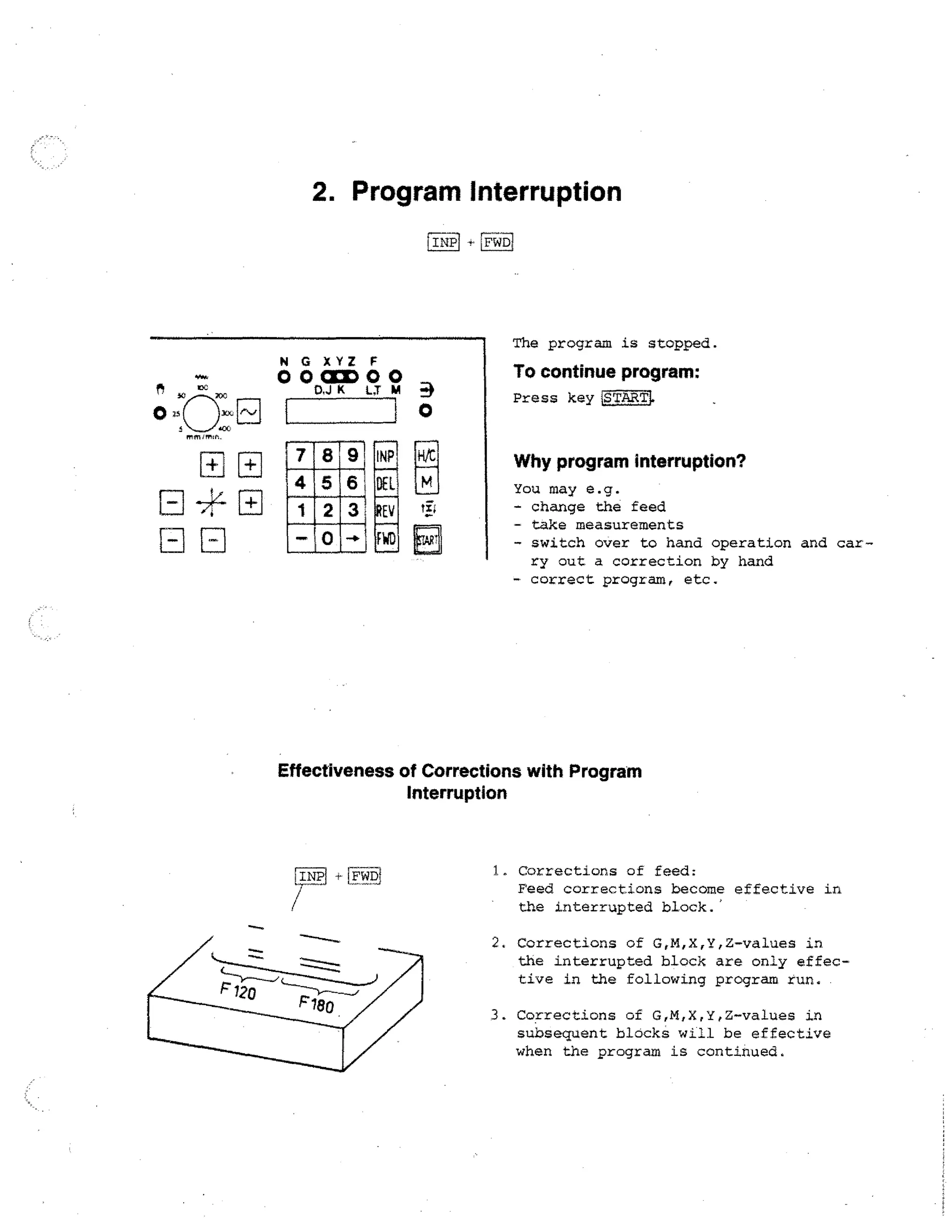
In terruption
+ IFWDi
Deleting a program
(DELI + (MP'
(first DEL)
set
Storing of Program I
program to NOO
IINPi + 'TZTV
Compare tape operation
RS-232 C operation
with
N](https://image.slidesharecdn.com/pemrogramancnctu-3a-140220040523-phpapp02/75/Pemrograman-cnc-tu-3-a-236-2048.jpg)

![The Figure Keys
You use the figure keys in order to enter the various values for address letters
X,Y,Z,F,G,M,D,T,L,J,K.
The entered values appear on the digital
read-out and/or on the screen of the monitor.
Fr] H.
-
The Minus-Sign Key ID
N G XYZ F
O 0=000
D,J K
L.J
1
°
9 I NP
H/C
6 DEL
M
2 3 REV 65
FWD
0
1,4j
R1
X,Y,Z values can have a minus or a plus
sign.
Pius sign input for X, Y, Z:
Put in figures only.
N G XYZ F
O 0CCIDOO
K
LX M
1400 0
H/C
Minus sign input
After input of figures, press EL] key.
The minus sign appears as a bar on the
digital read-out.
M
Example:
tit
X = -1400
Input: Ly4 PEI](https://image.slidesharecdn.com/pemrogramancnctu-3a-140220040523-phpapp02/75/Pemrograman-cnc-tu-3-a-246-2048.jpg)
![The fistiiiKey = Memory Key
]INP! = Abbreviation for . Input
LIN
= Instruction to the computer to
register the entered value.
N G XYZ F
0003)00
D.J K L,T M
1
89
4 5 6
1 2 3
— 0 -4-
Digital read-out
N G XYZ F
r
DEL
REV
FWD
FTAPT
Example
23501
- Entex value12350 The number
appears for your information
only, it is not in the computer yet.
00CICI►OO
K
M
718 9I TWP-1
Monitor
CNC OPERATION
K L,T M
N G XYZ F
d
IINP
Lamp X lights up.
0001:11D00
L
I
o
H/C
- You press INP. By pressing
this key, figures are registered; at the same time
the number 2350 disappears
and the light jumps to the
next address letter.
M
Note
With1INPi you can also jump forward in the
block.
, N G _x_ Y
235000I
01!](https://image.slidesharecdn.com/pemrogramancnctu-3a-140220040523-phpapp02/75/Pemrograman-cnc-tu-3-a-247-2048.jpg)
![The FWD Key
Instruction: to jump forward block-by-block
N G XYZ F
000137300
Mw
0
D.J K LT M
:s3r,
-5
).743
I r,-1]
0
111111E111
NEI
X
(J) (D)
(K)
y
(S)
(L) (T) (H)
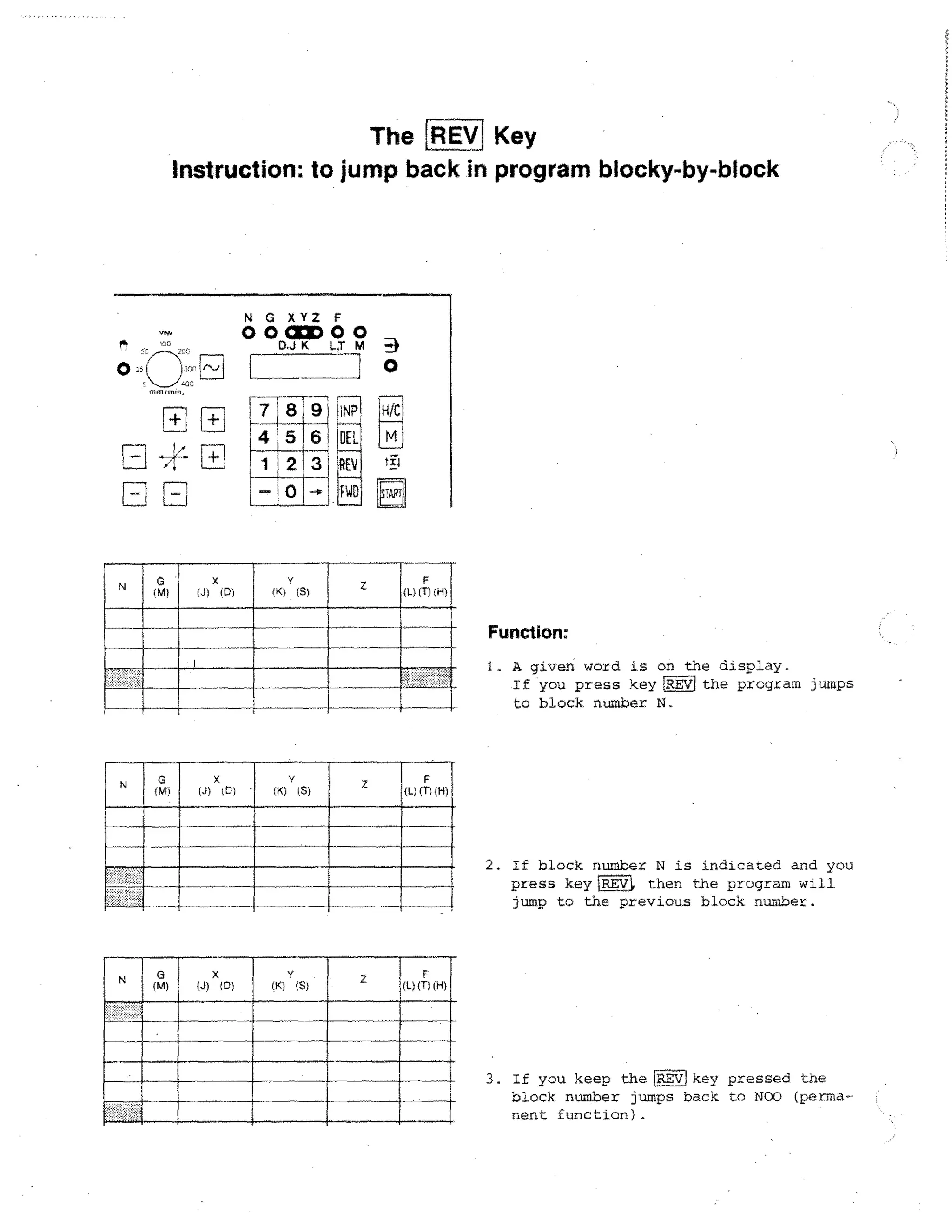
1. A given word is displayed. By pressing the IFWD1 key the program jumps to
the next block numher.
2. If a block number is indicated: when
pressing the FIE key the program
jumps to the next block number.
F
(L)
(H)
3. If you keep the iniD key pressed down,
the program will jump block-by-block
to the program end.](https://image.slidesharecdn.com/pemrogramancnctu-3a-140220040523-phpapp02/75/Pemrograman-cnc-tu-3-a-249-2048.jpg)
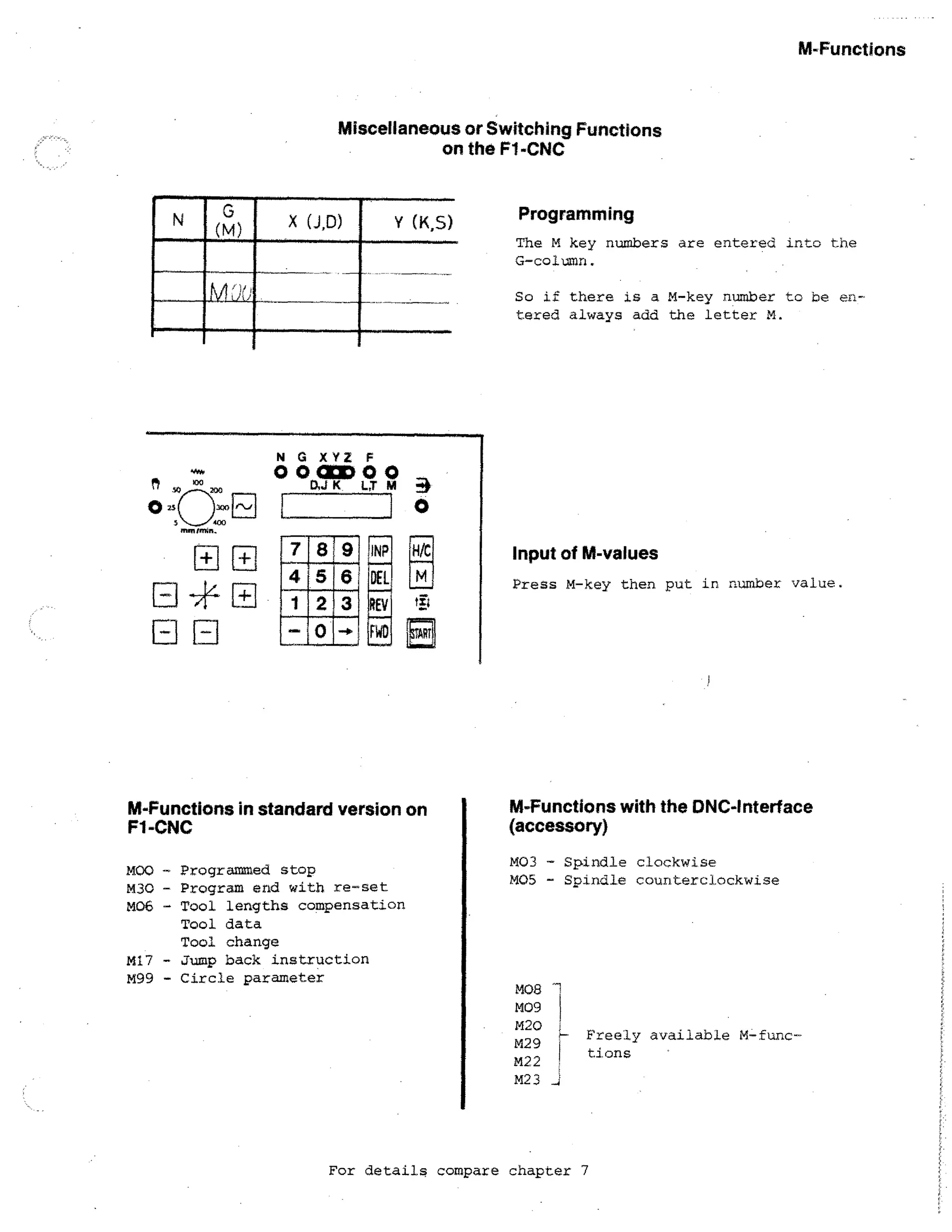
![Input of M-Values
0
If you want to put in M-values: at
first you have to select the M-key.
The M--value is programmed in the
G-column.
L_J
r
N
G XYZ F
00CCD00
D,J K LT
m
3
0
Input: M30
Address G has to be shown
INP
4 5
N
Monitor
Example
Digital read-out
6 DFL
H/C
M
G XYZ F
N G: X
00
Press P,T
Put in
0 0 OM 0 0
CNC OPERATIONS
ill
30 0
CNC OPERATION
D,J K LT M ••
N;G: X
Press IINT] (register)
,
oo(
H/C
14 M3^i
Attention:
▪ M-values are not taken over by
pressing INP
-i- If you press INP after M30, the
program jumps back to NOO.
A 1S
Y](https://image.slidesharecdn.com/pemrogramancnctu-3a-140220040523-phpapp02/75/Pemrograman-cnc-tu-3-a-252-2048.jpg)
![Inserting and Deleting of Blocks
N G XYZ F
yil4- -nserting a block
;,_7J
Deleting a block
0001:000
K
CC
1.7
rk..
1
mmm.m.
7 8
12
45 i
H
1
.—
.
--170
,INPi !0-
63
!
Remark 1:
First press key viand
(keep1,--, !pressed).
Remark 2:
Perranent function when you carry on
pressing (more than 0,6 sec.), i.e.
you insert permanently empty Ilnes •.A74Ch
I
,REV .1;
0
}L °f
then key INPI
ids R
G21.
N G XYZ F
Example: Inserting
0 0 CUD 0 0
D,J K L;T M
+ Digital read-out shows block a02
02
M
IIIIII
•
all
TM
(J) X (D)
0
00
00
4
MEI
04 ga
0
00
03
r
00
01
2
01
o
2.
0
F
(L) CT) (H)
Z
0
0
o
o
400
400
0
0
►►
r
=
2.5o
0t
0
•
.0
loo
0
0
400
C1
►o
OS
3o
00
00
04
04
0
0
Press
FITTIT1
+ In block NO2, G21 is automatically
written.
+ The original block NO2 is automatically changed over to NO3 - also all
subseauent blocks to the next block
number.
+ In block NO2 you can program required
instructions as you want.
Procedure
0
01
[INP1
1 0
26-0
03
04
0
1500
0
►
IN
+ Delete G21
+ Put in wanted bleCK
Do
0
0
0
- do
400
Example: Deleting
IDEL]
+ Digital read-out shows NO2
Press!,-.../14DELI
NO2 is deleted
All subsequent blocks are backnumaered: NO3 - NO2, N04 - NO3, etc'.](https://image.slidesharecdn.com/pemrogramancnctu-3a-140220040523-phpapp02/75/Pemrograman-cnc-tu-3-a-254-2048.jpg)
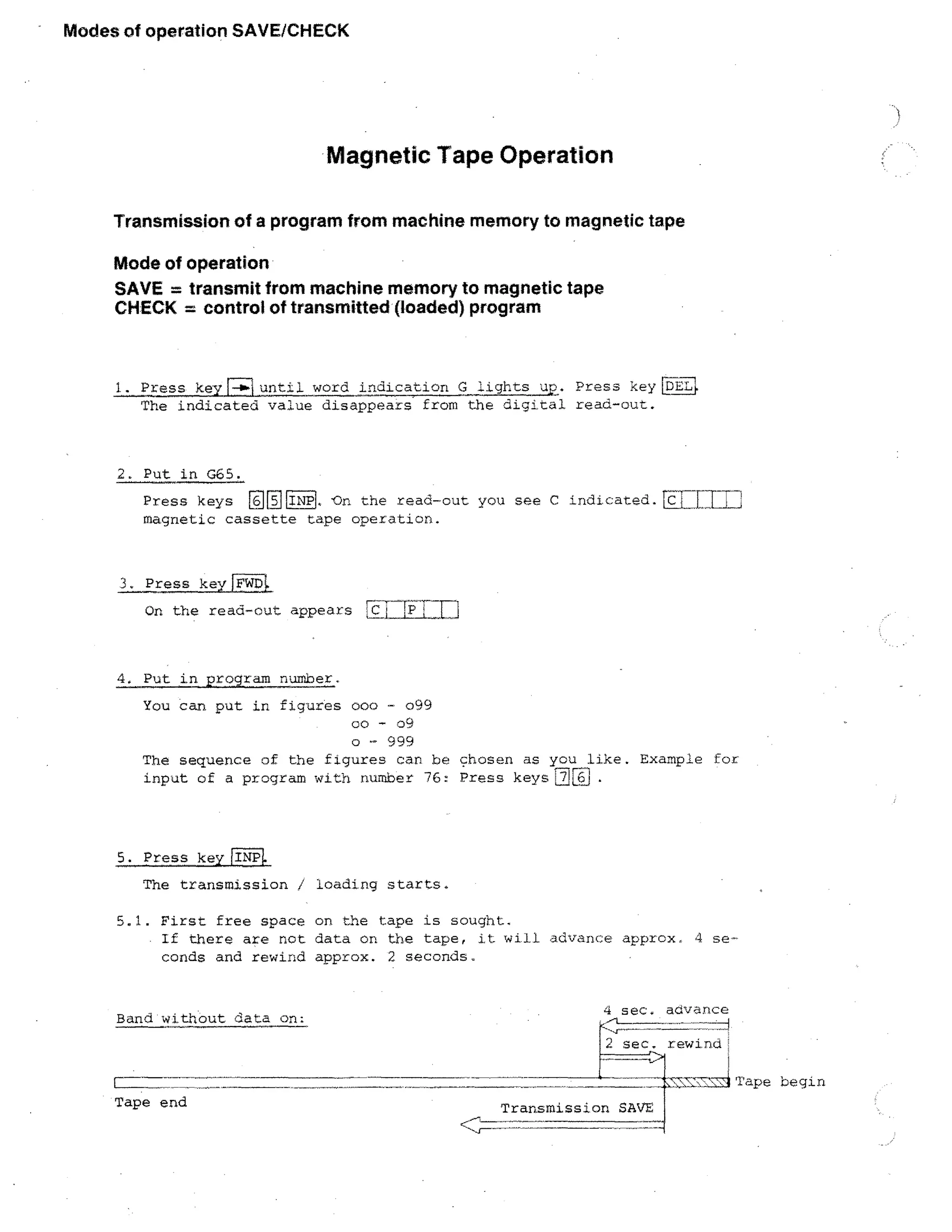
![Mode of operation LOAD
Transmission of program from tape to machine memory
Mode of operation LOAD
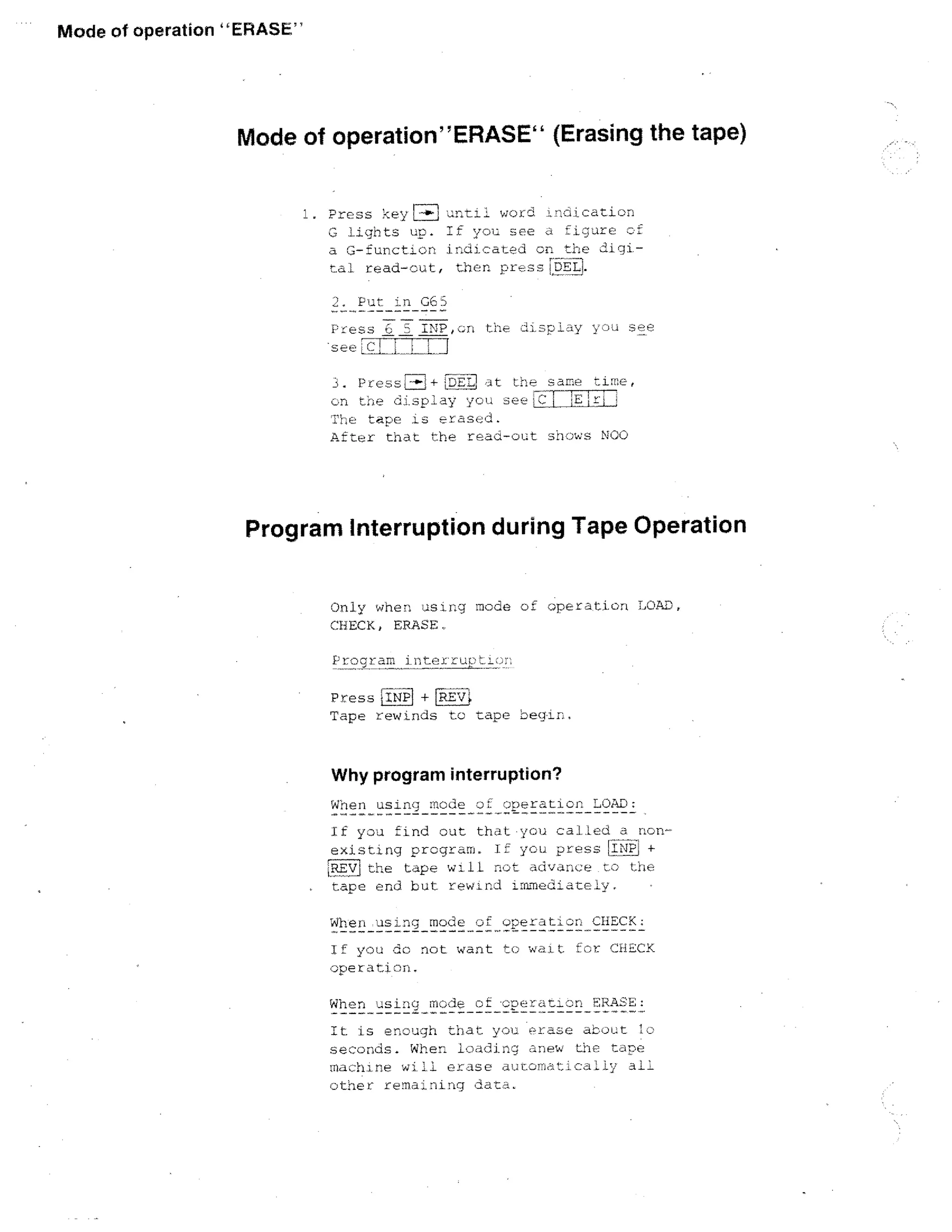
1. Press key [-1►1 until word indication G lights up. If a figure of the
6-function appears, press key DEL. Then indication on read-cut
disappears.
2. Put in 065.
Press keys
EcIE
INP . Read-out indicates
ir- 1
1
3. Press key INP.
Read-out indicates
4. Put in number of program.
E.g. for program number 76 you press keys 1777iL On read-out; Lc
1
PL.
6:
5. Press keylINPI.
5.1. The program number CC is looked for.
If you have other programs on the tape already, then these numbers
appear on the digital read-out.
E.g. IC
P:214
or
[c
[715
5.2. Loading:
When the wanted program 76 is found, the loading operation starts.
On the digital read-out you see TE]
LO is the abbreviation for load.
5.3. After the loading is done, the tape rewinds. The read-out shows NOO.
Program number 76 is stored in the machine computer.
6. If you press keyISTART) then the program starts operating.
Program 76 1 Program 75 _LT- Program 74. j Tape begin
rrET
0
P
7151
is
L7
P„.._,
1_
4](https://image.slidesharecdn.com/pemrogramancnctu-3a-140220040523-phpapp02/75/Pemrograman-cnc-tu-3-a-278-2048.jpg)
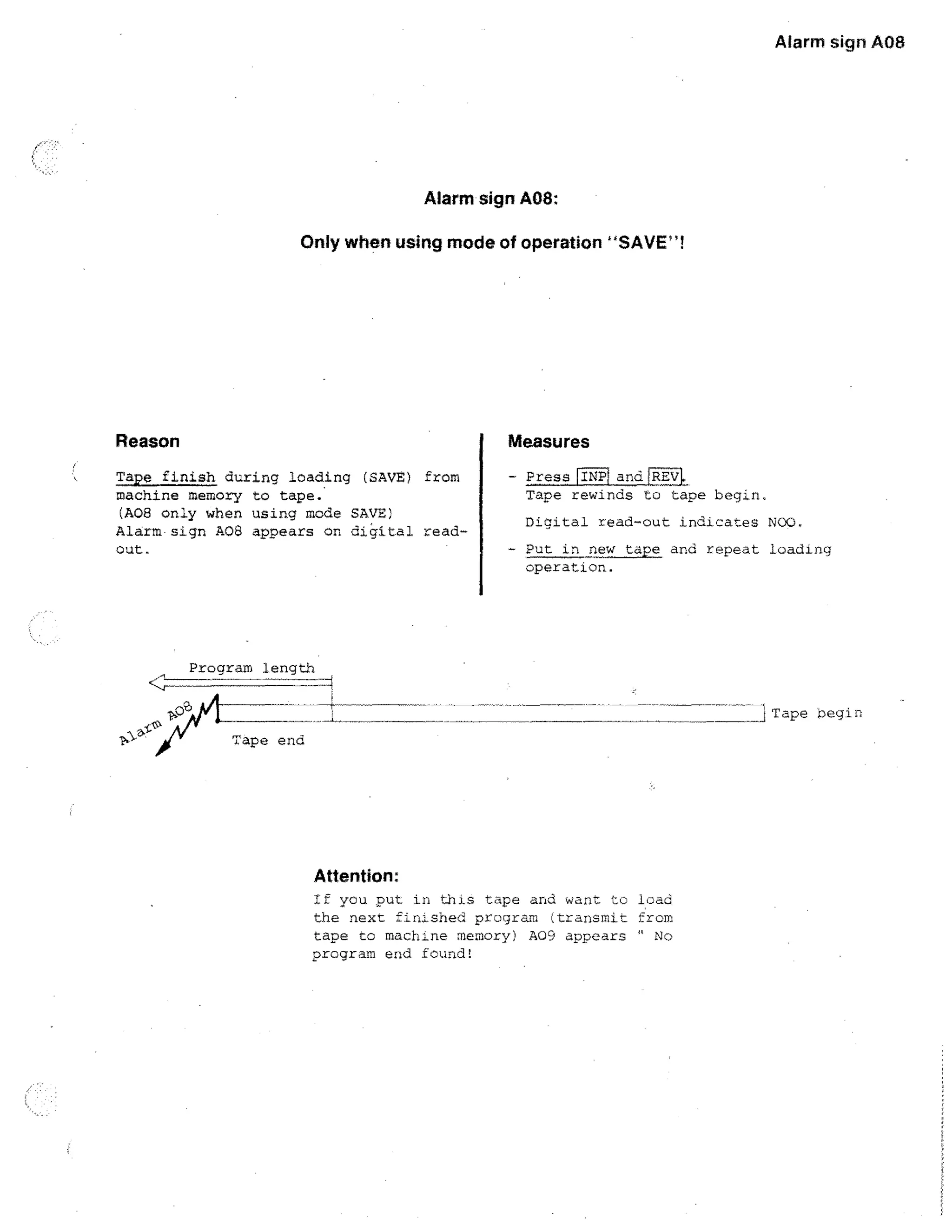
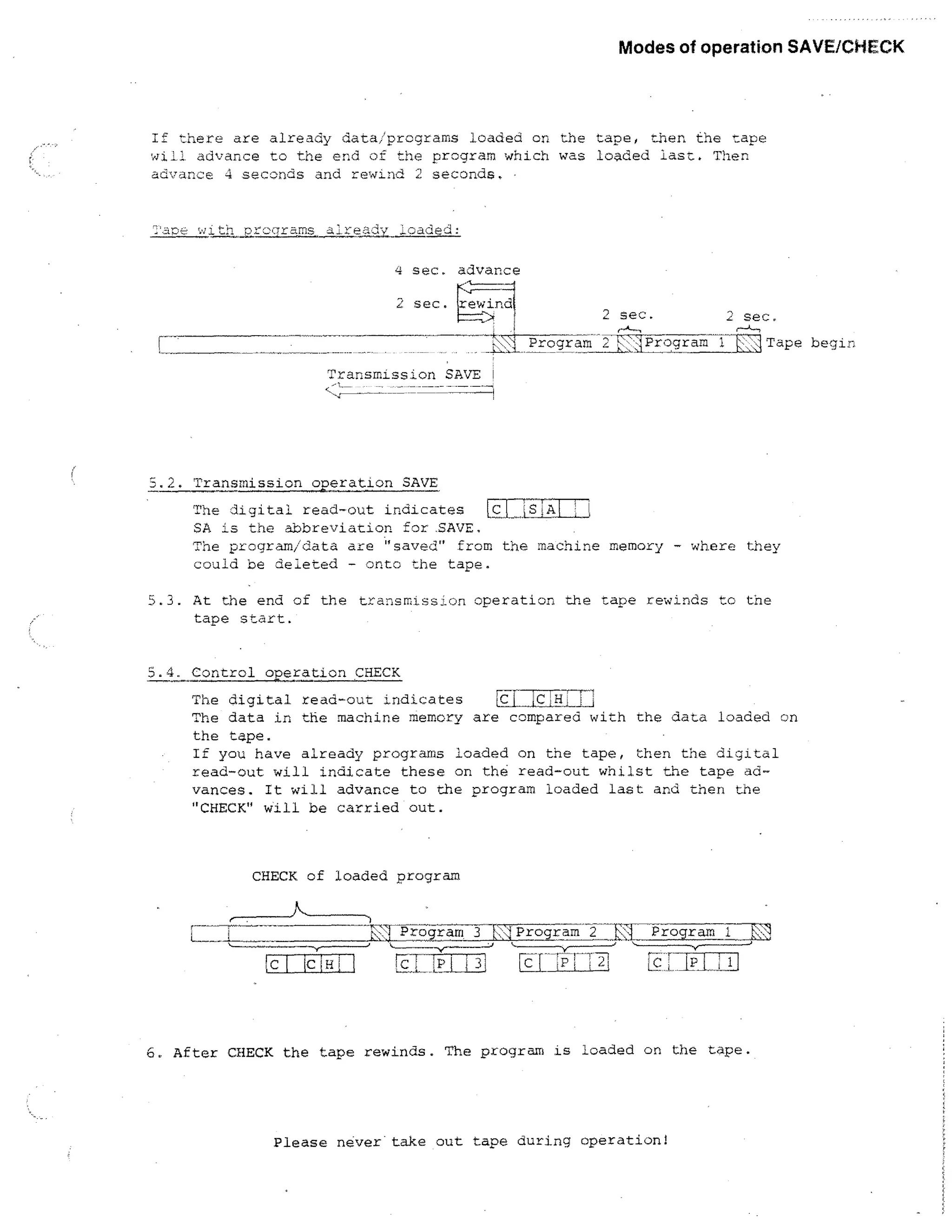
![Alarm sign
Auti
Alarm sign A09:
Only when using mode of operation LOAD!
A09 - Reason 1
Measures
Selected program not found.
If you call a non-existing program number when loading ;from ta p e to machine
memory), then alarm A09 appears.
- PressiINP + 1REvl
The tape rewinds. The digital read-cut
indicates after chat NOO.
- Look for program on another tape (in
case you are sure you put it in).
Example: You Look. on this tape for prcno. n
Pr.NrhE.
A09 - Reason 2
Measures
Selected progran not fully on ta p e (m06),
since tape was finished when loading
from machine memory to tape (already in
mode o!f operation SAVE you had alarm A06).
- Press [INP1 +Fa]
Tape rewinds, read-out indicates NOC,
- Look for program on other tape (in case
you are sure that you put it in;
Example: You call. on program no.19
Program do es not nave M06, thus alarm
AOb was indicated aiready during mode of
operation SAVE.
[
19
IA
17
16](https://image.slidesharecdn.com/pemrogramancnctu-3a-140220040523-phpapp02/75/Pemrograman-cnc-tu-3-a-282-2048.jpg)
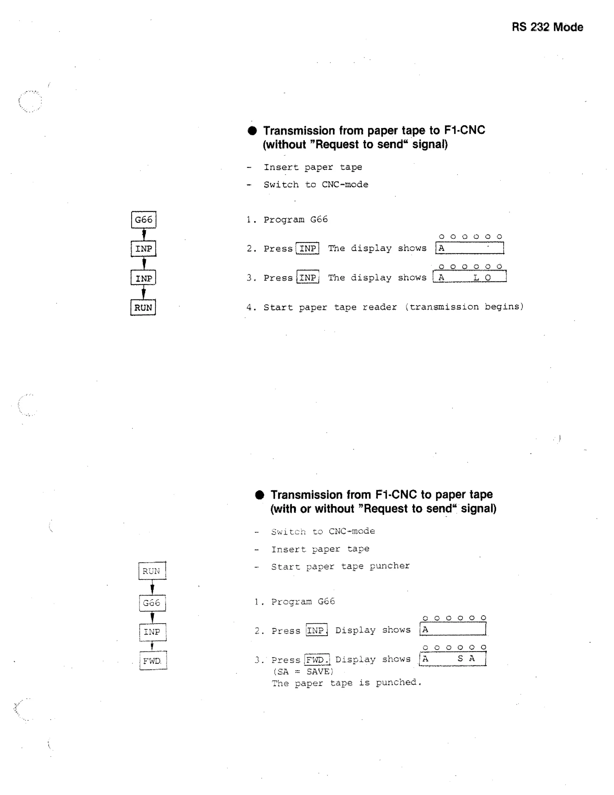

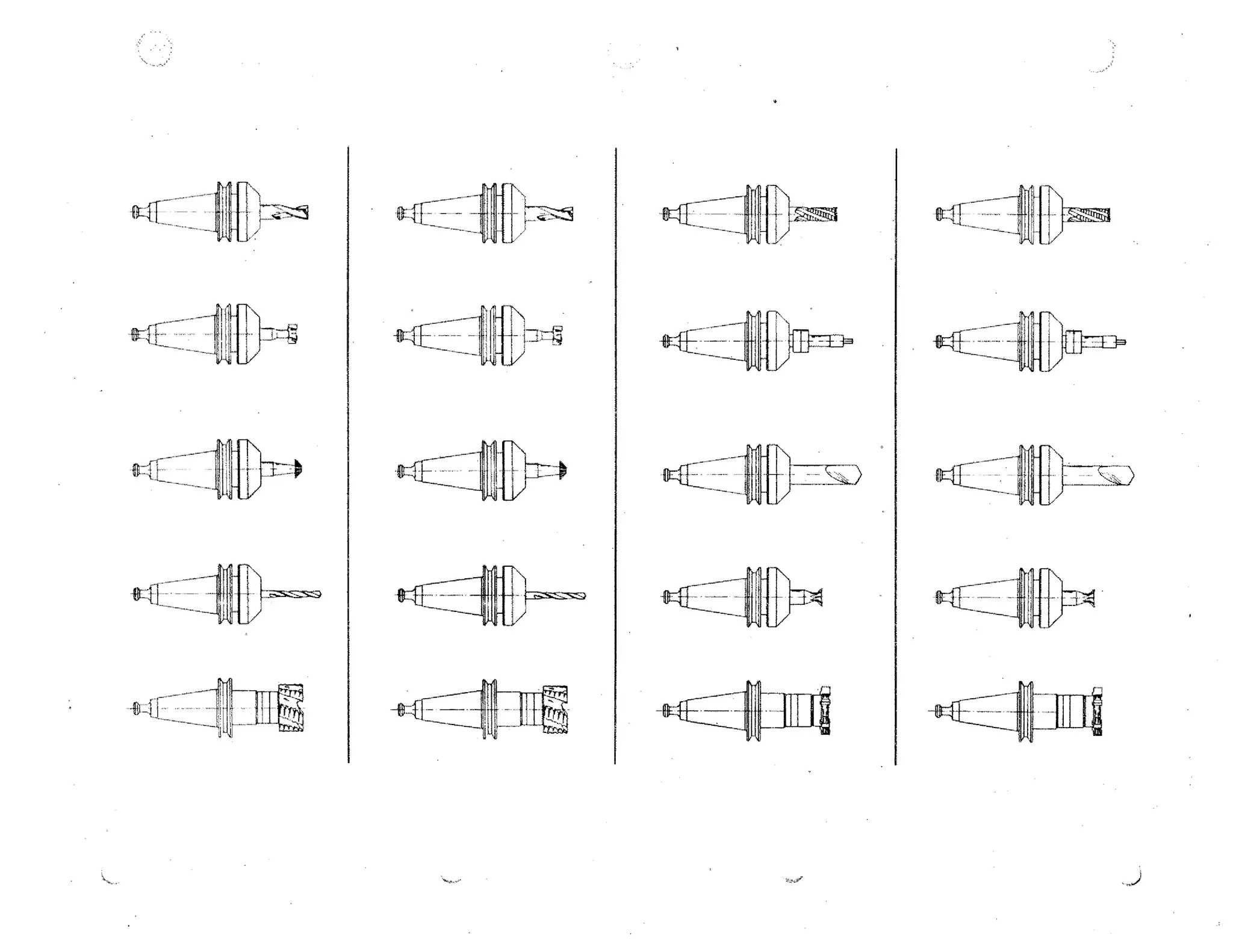
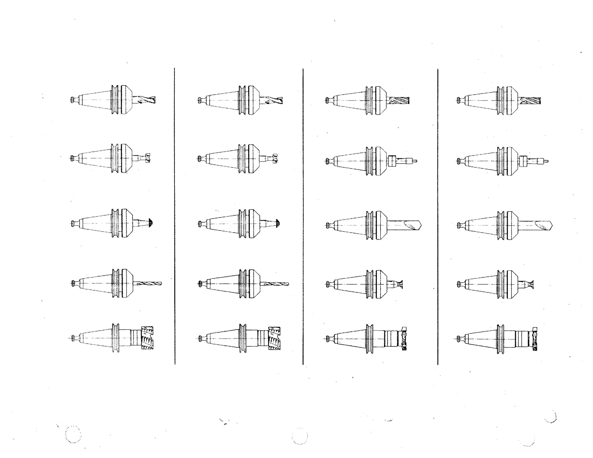

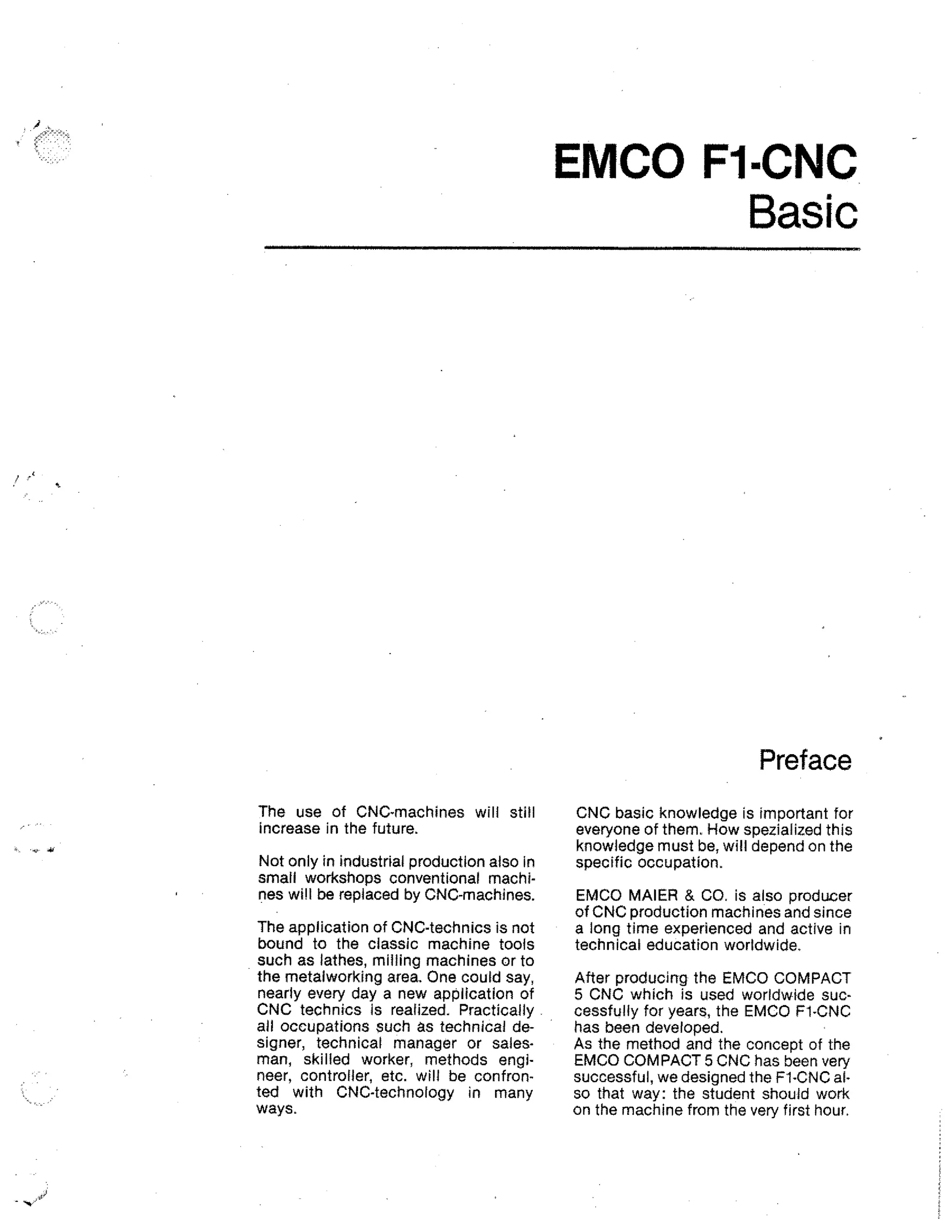
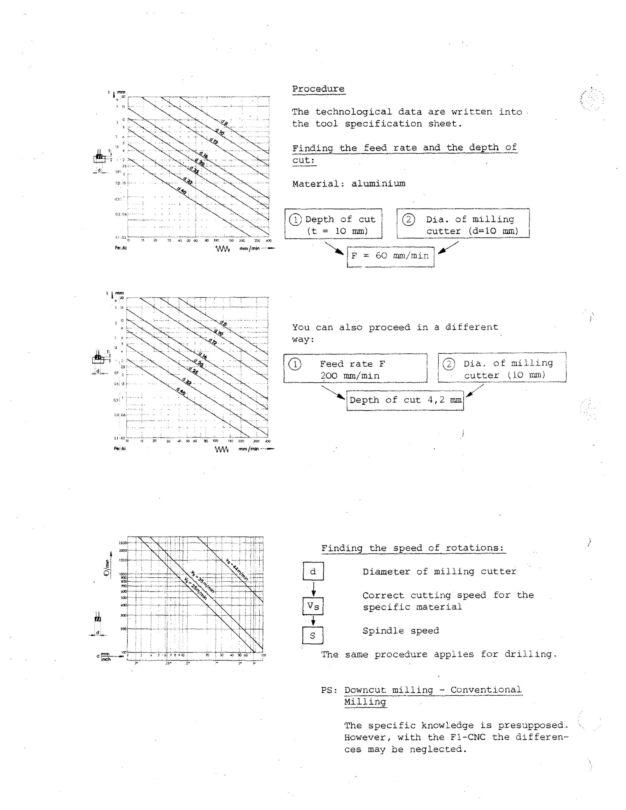
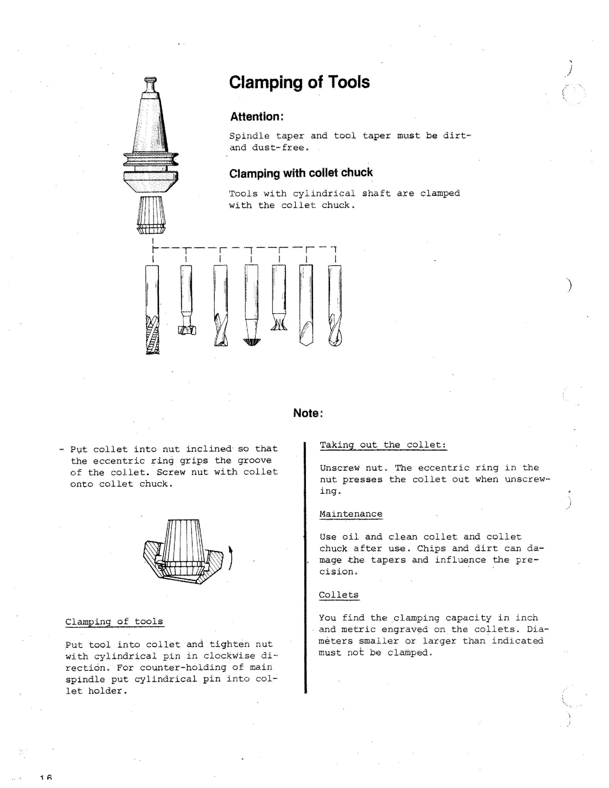
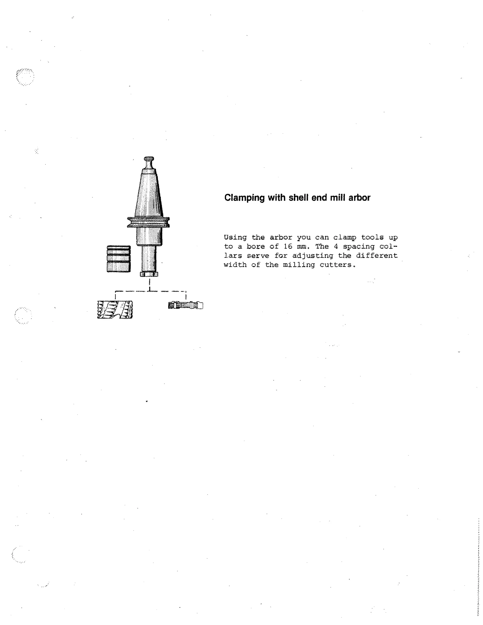
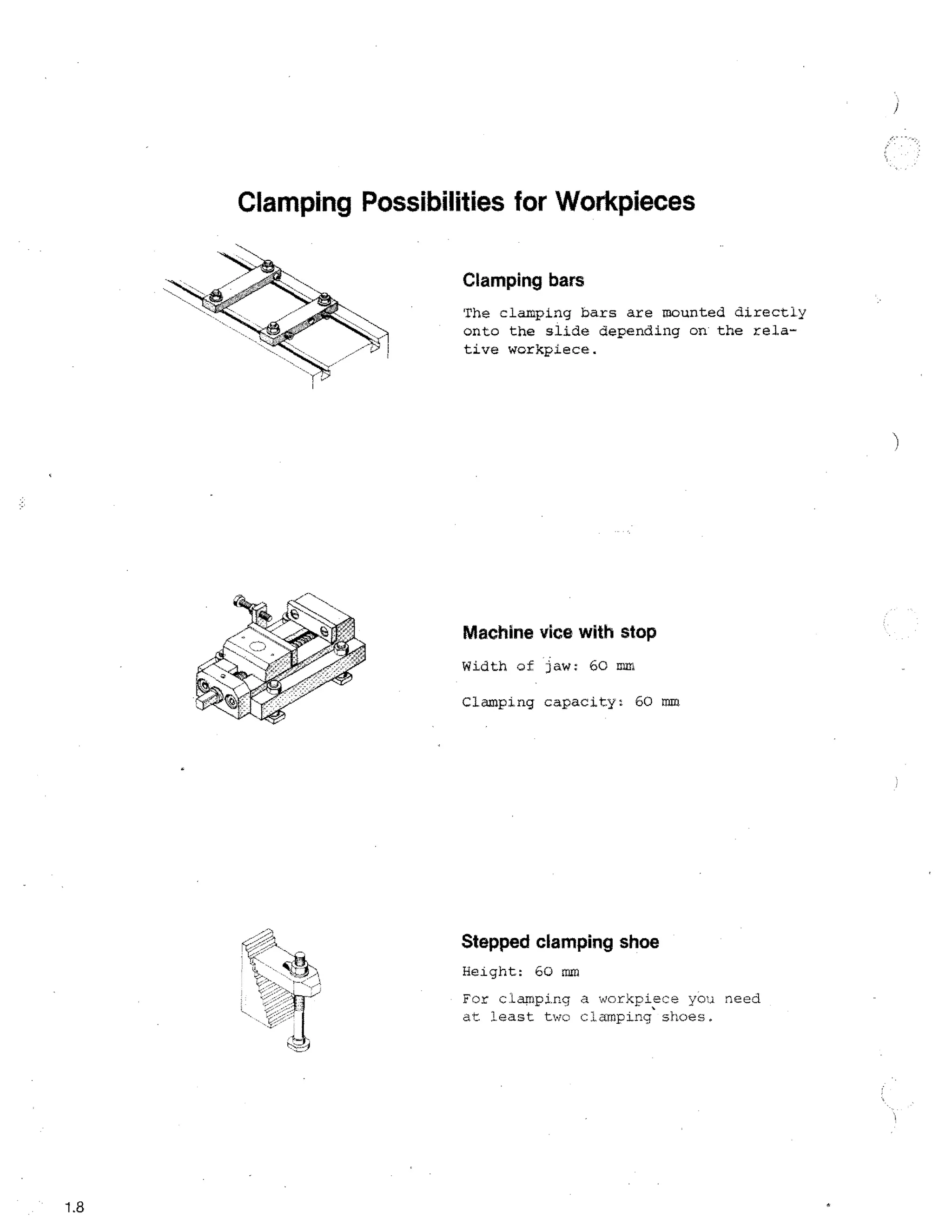
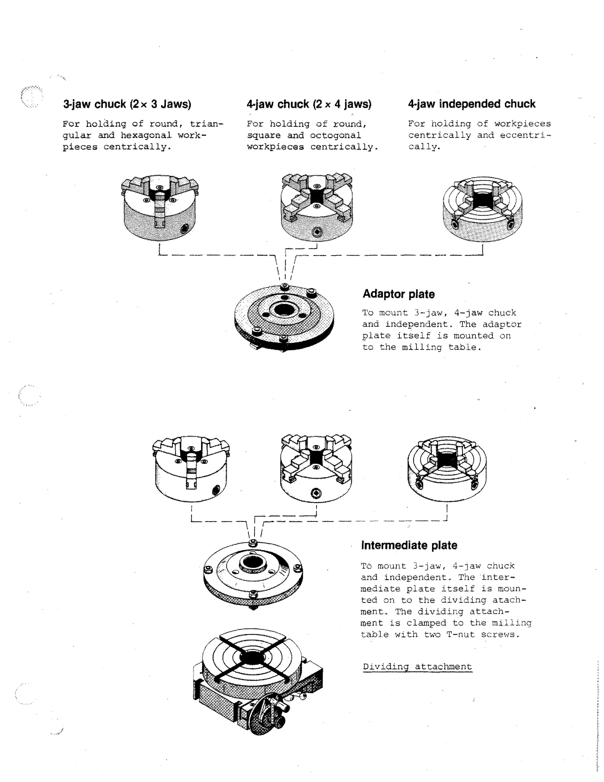
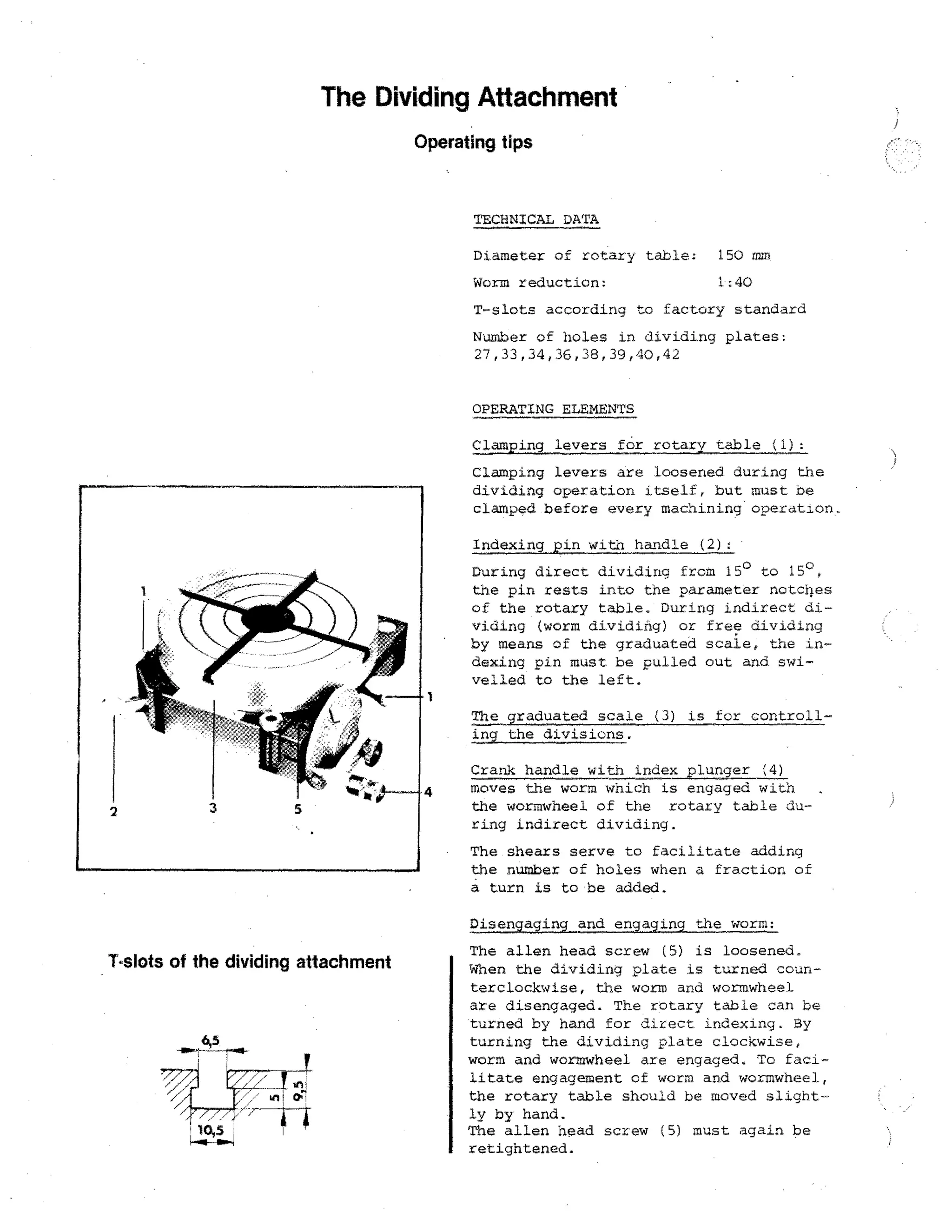
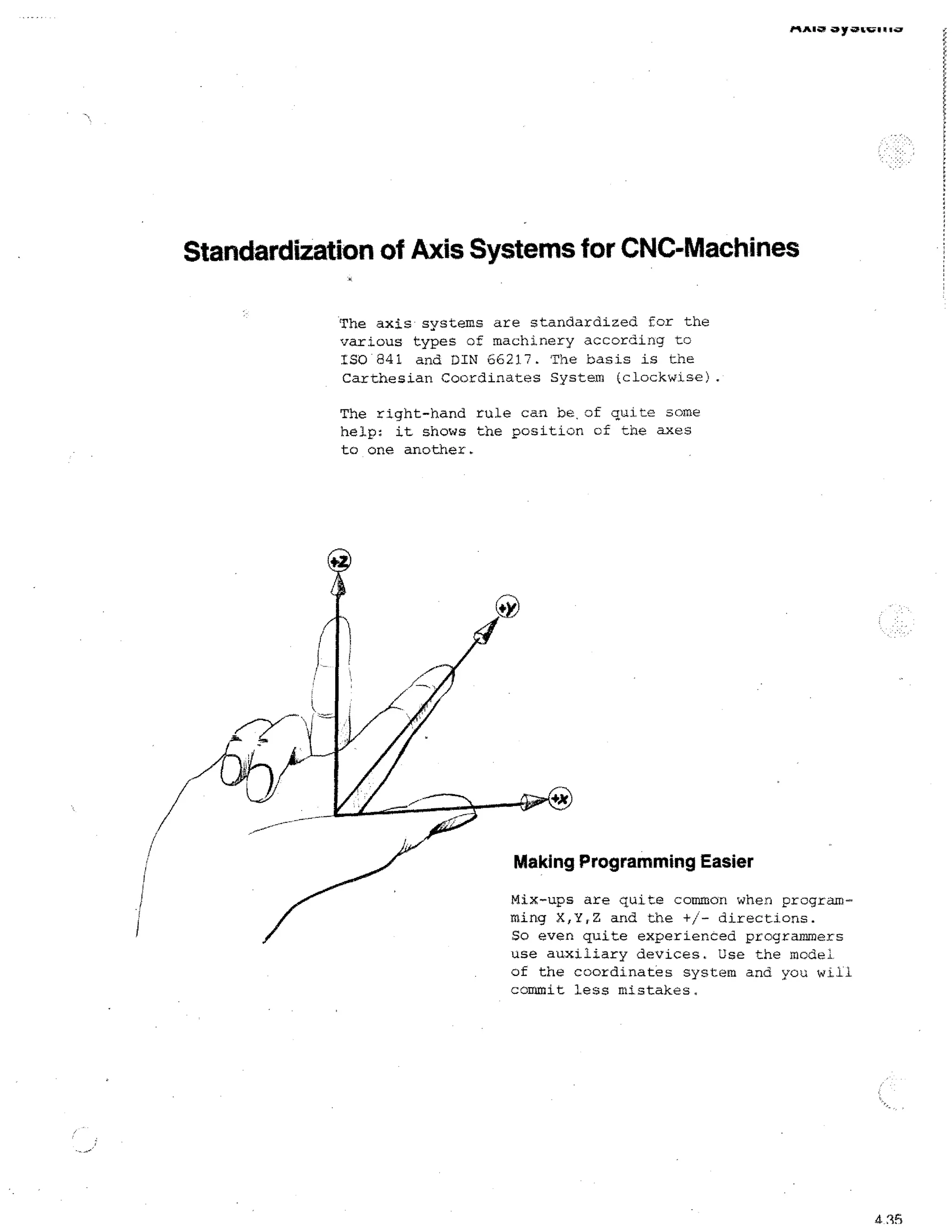
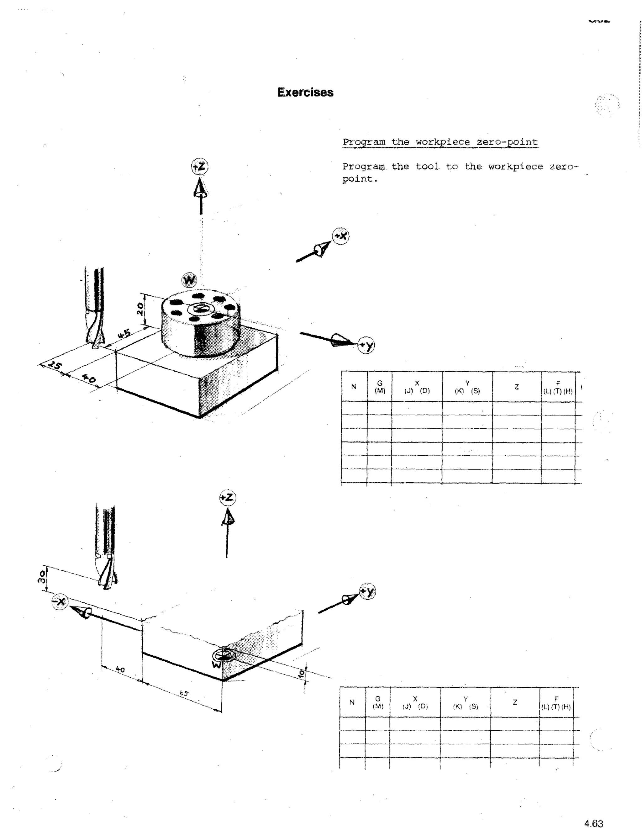
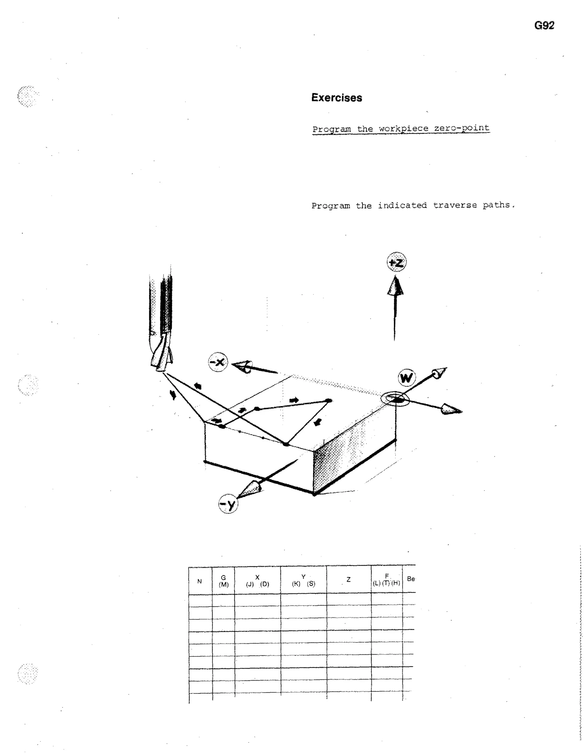
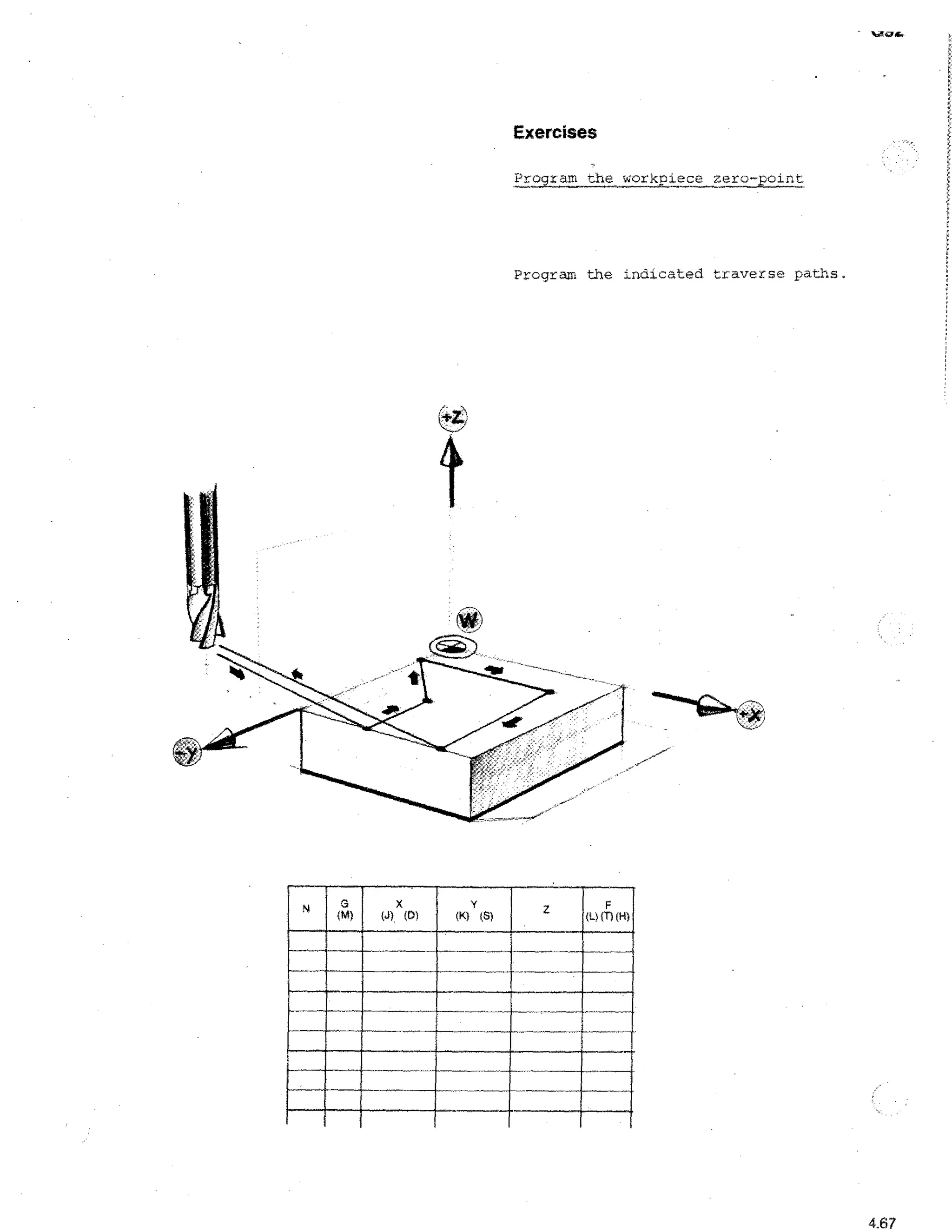
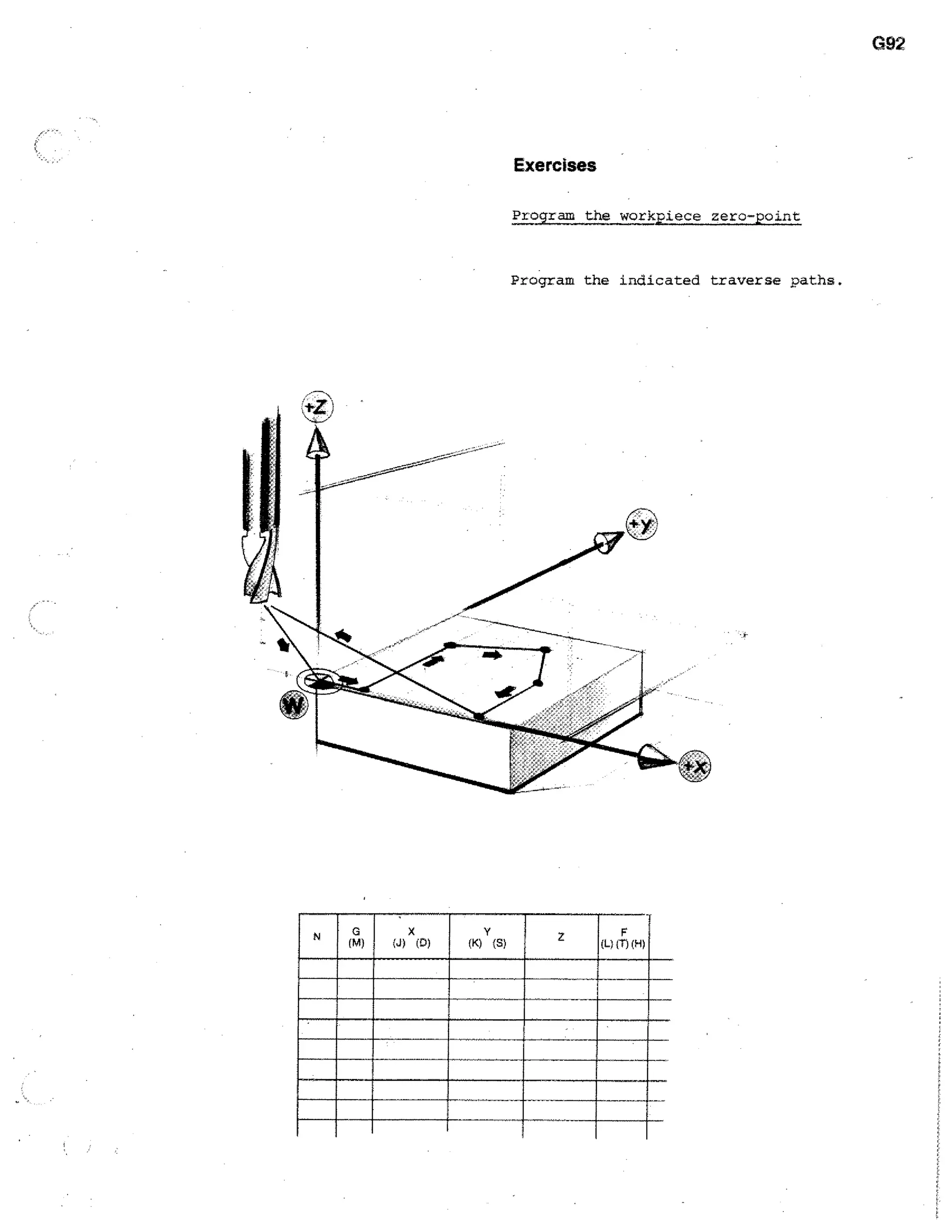
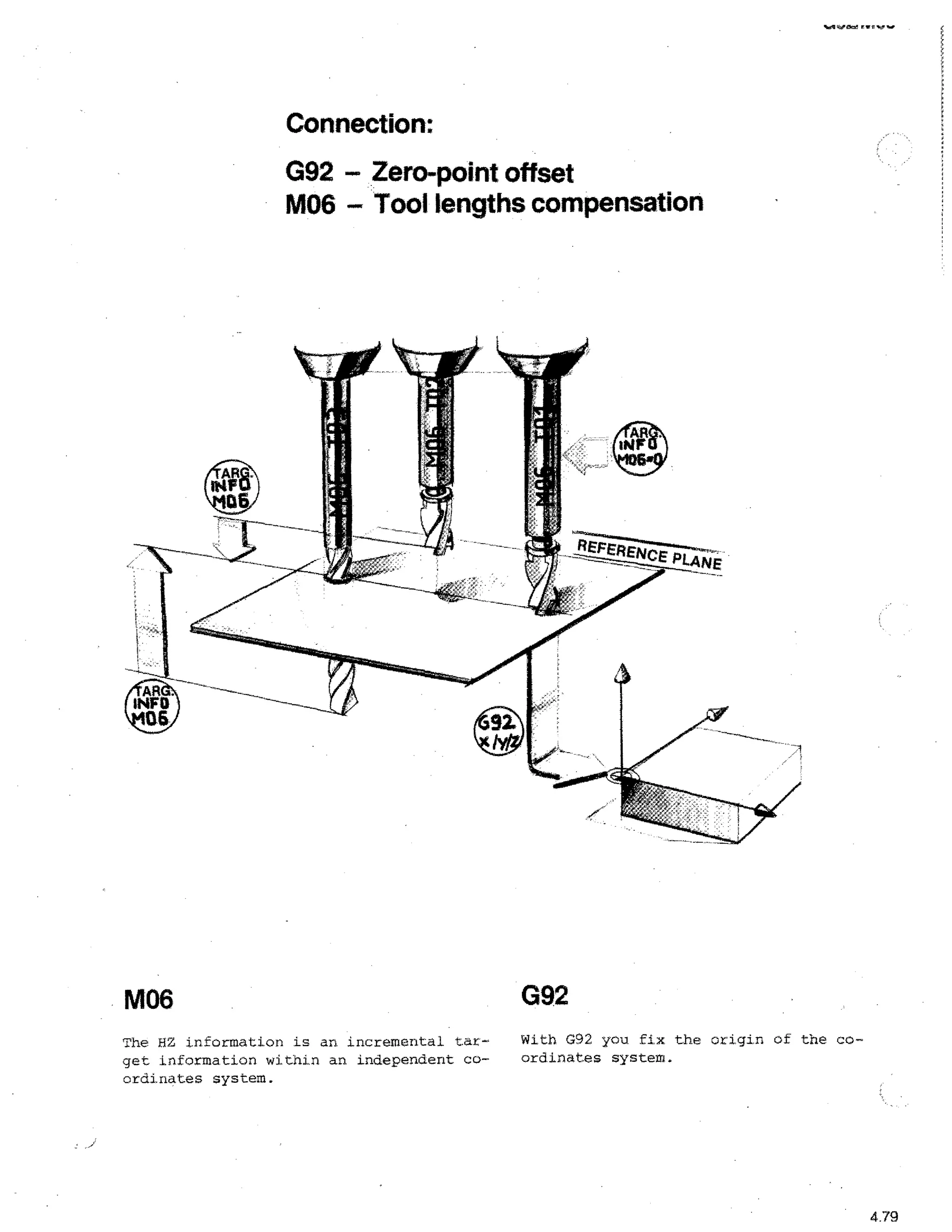
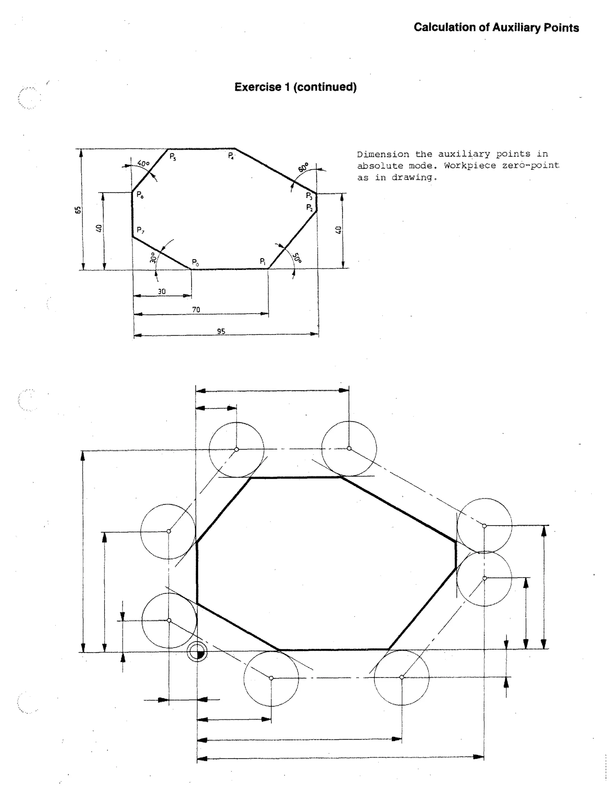
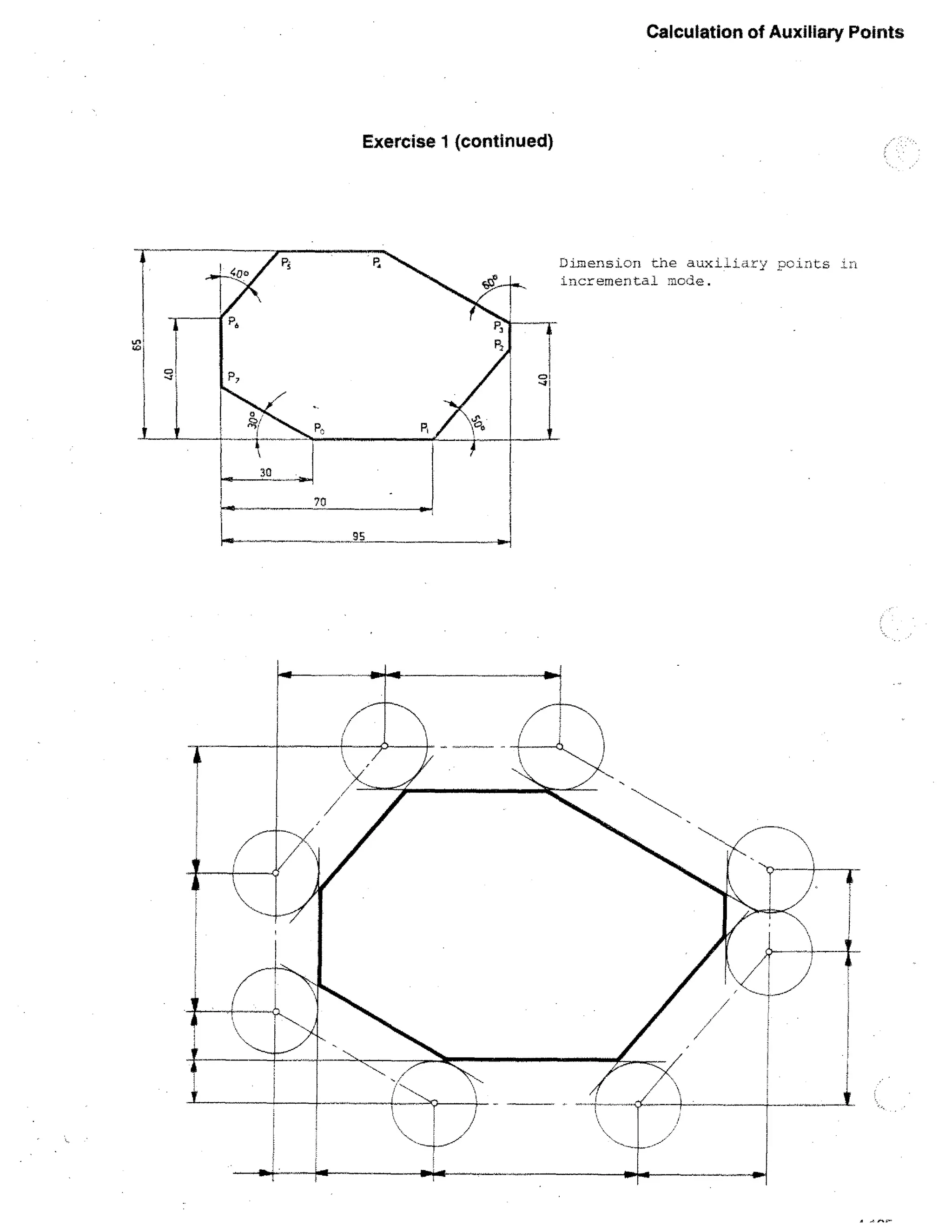
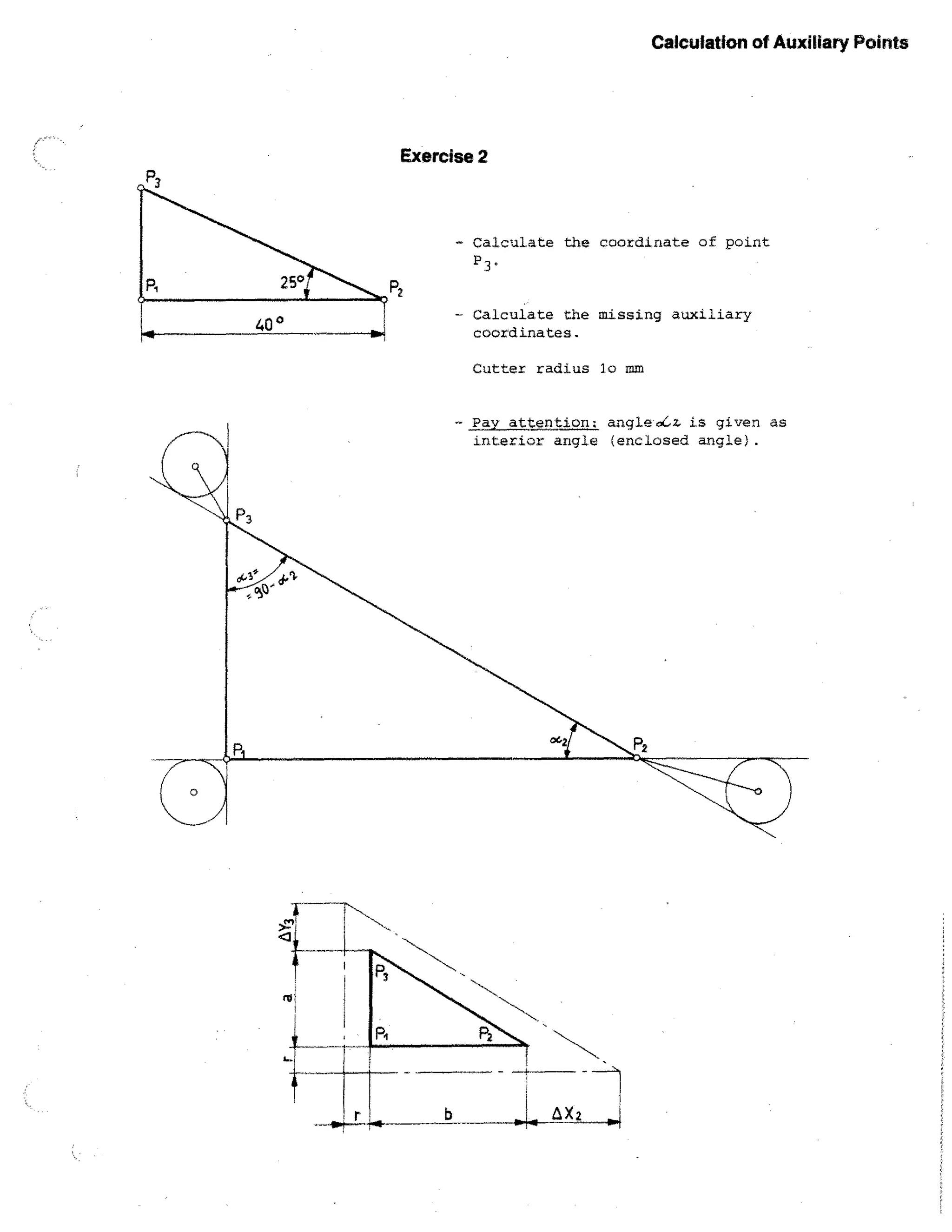
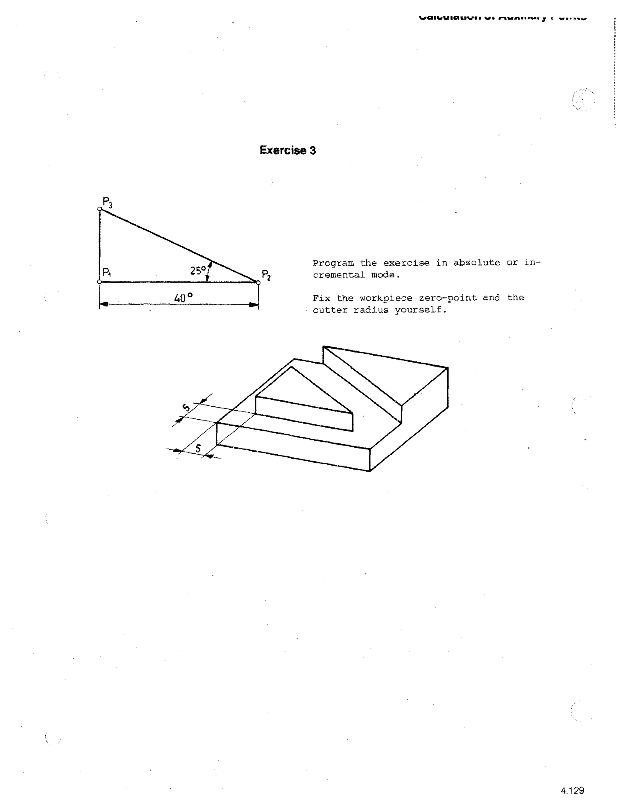
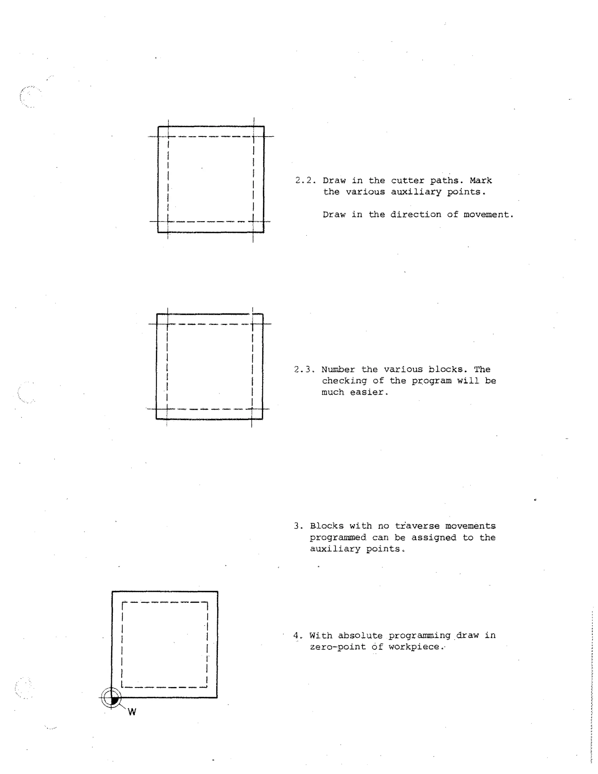
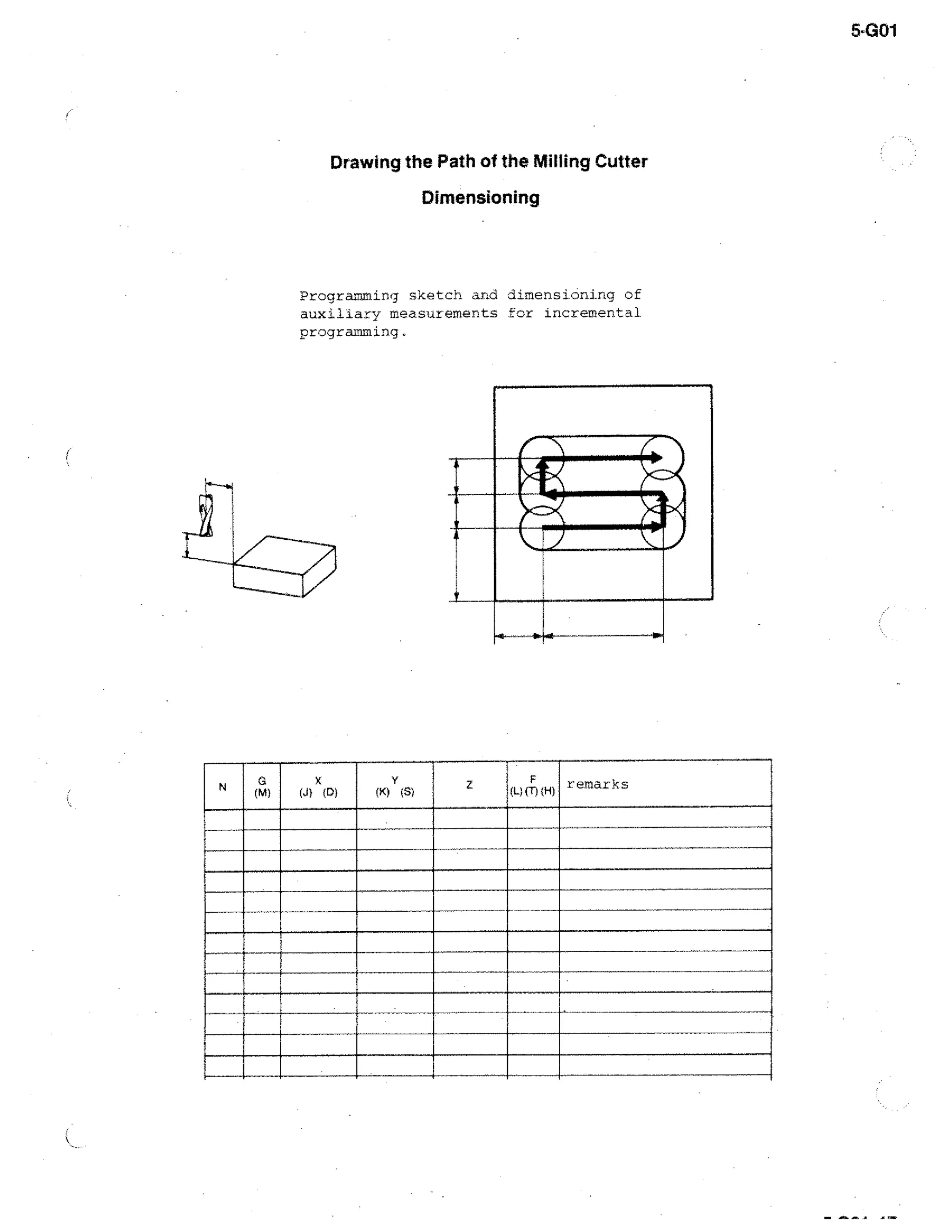
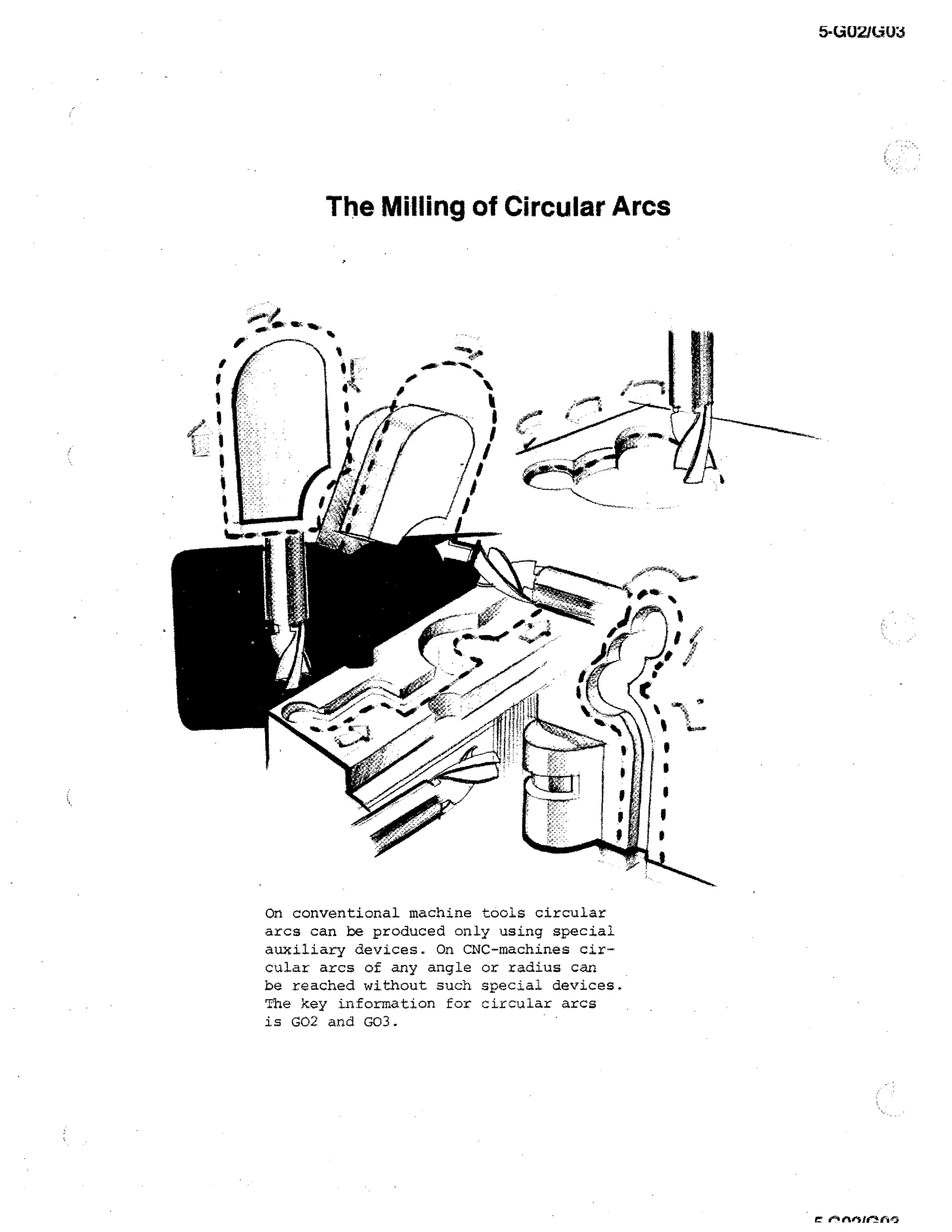
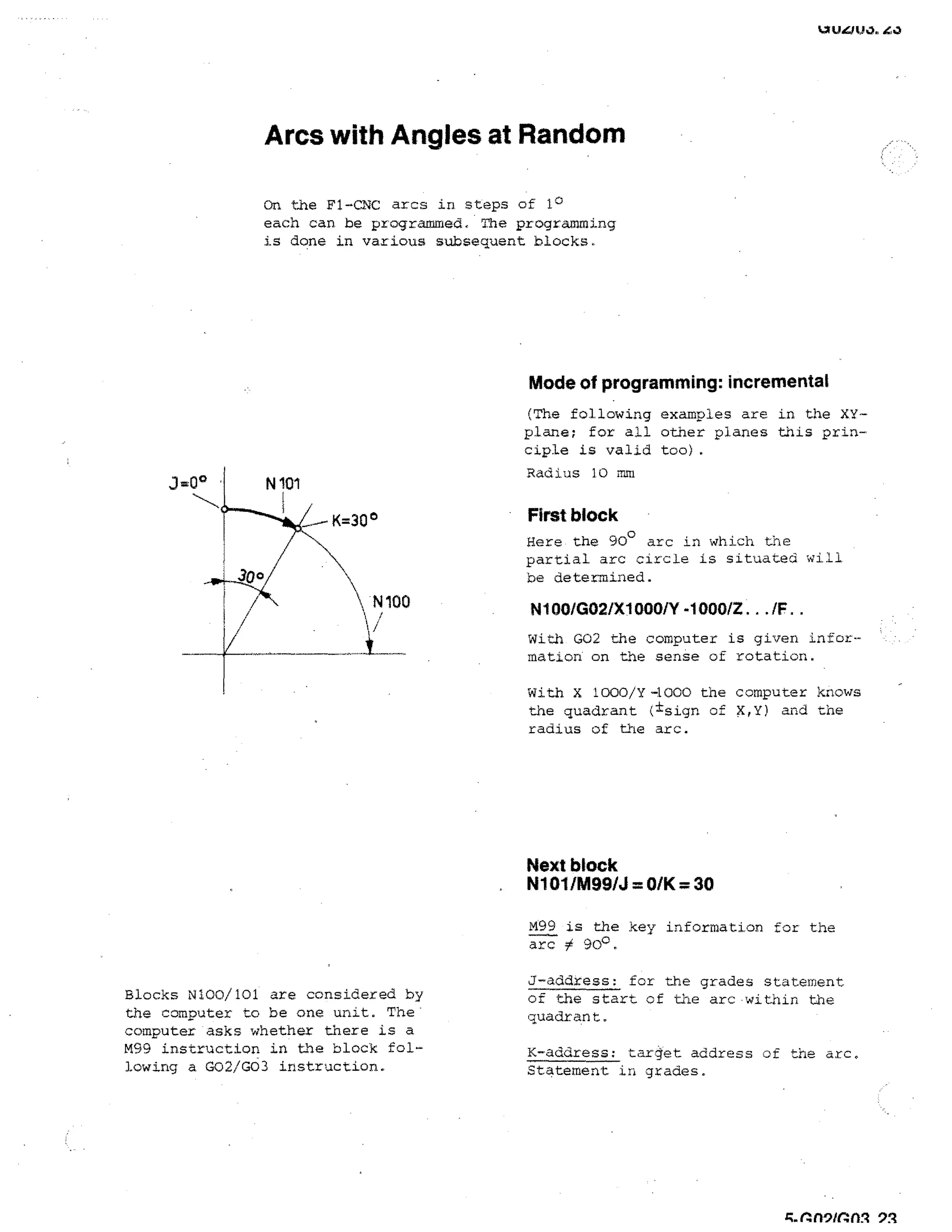
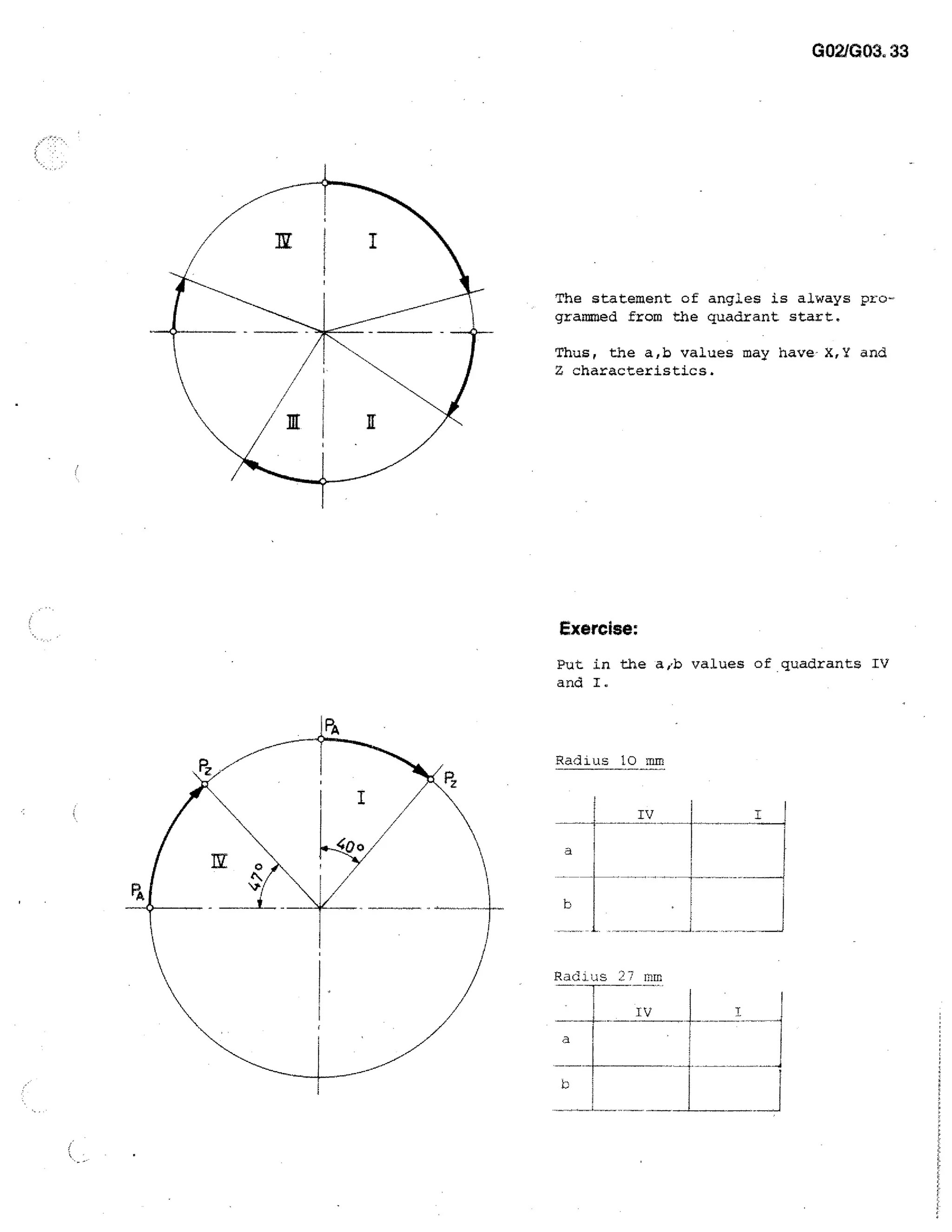
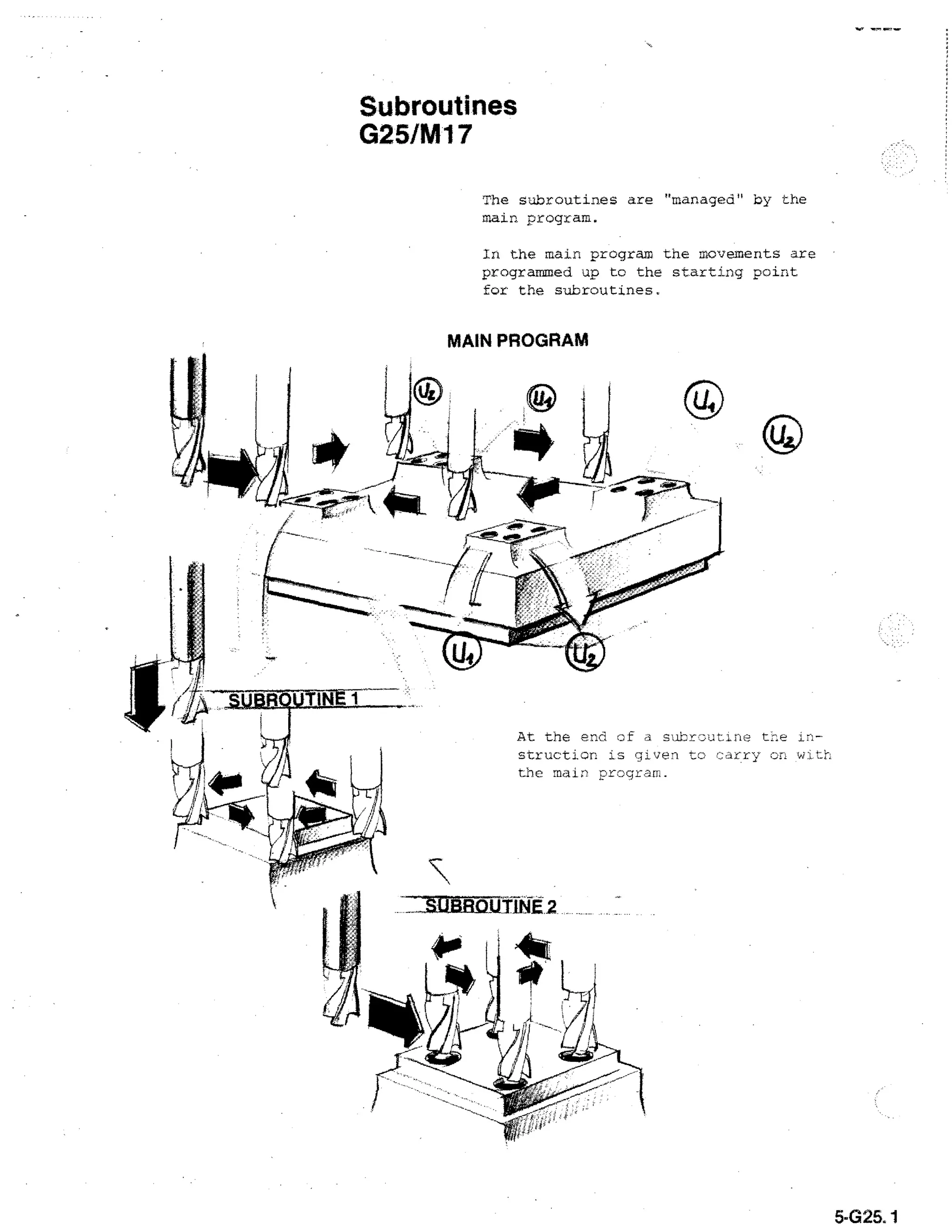
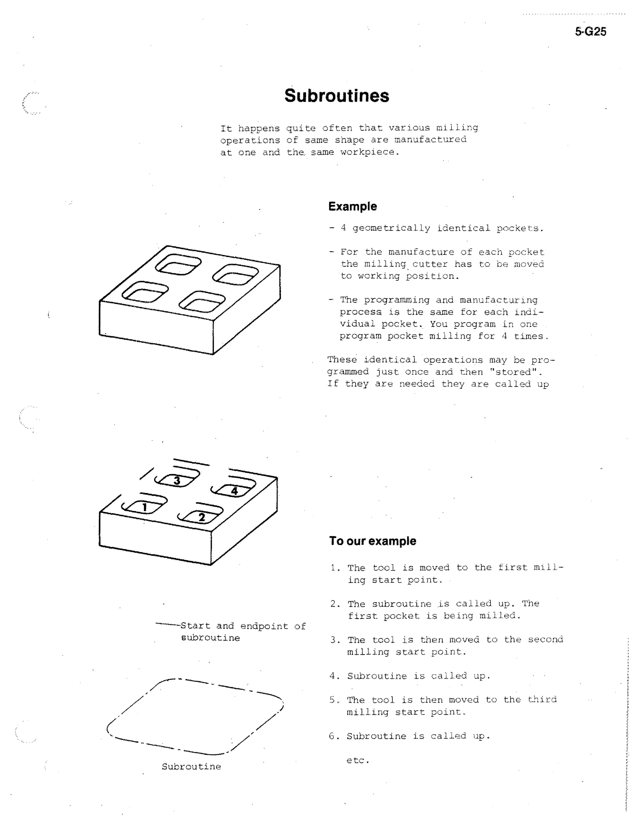
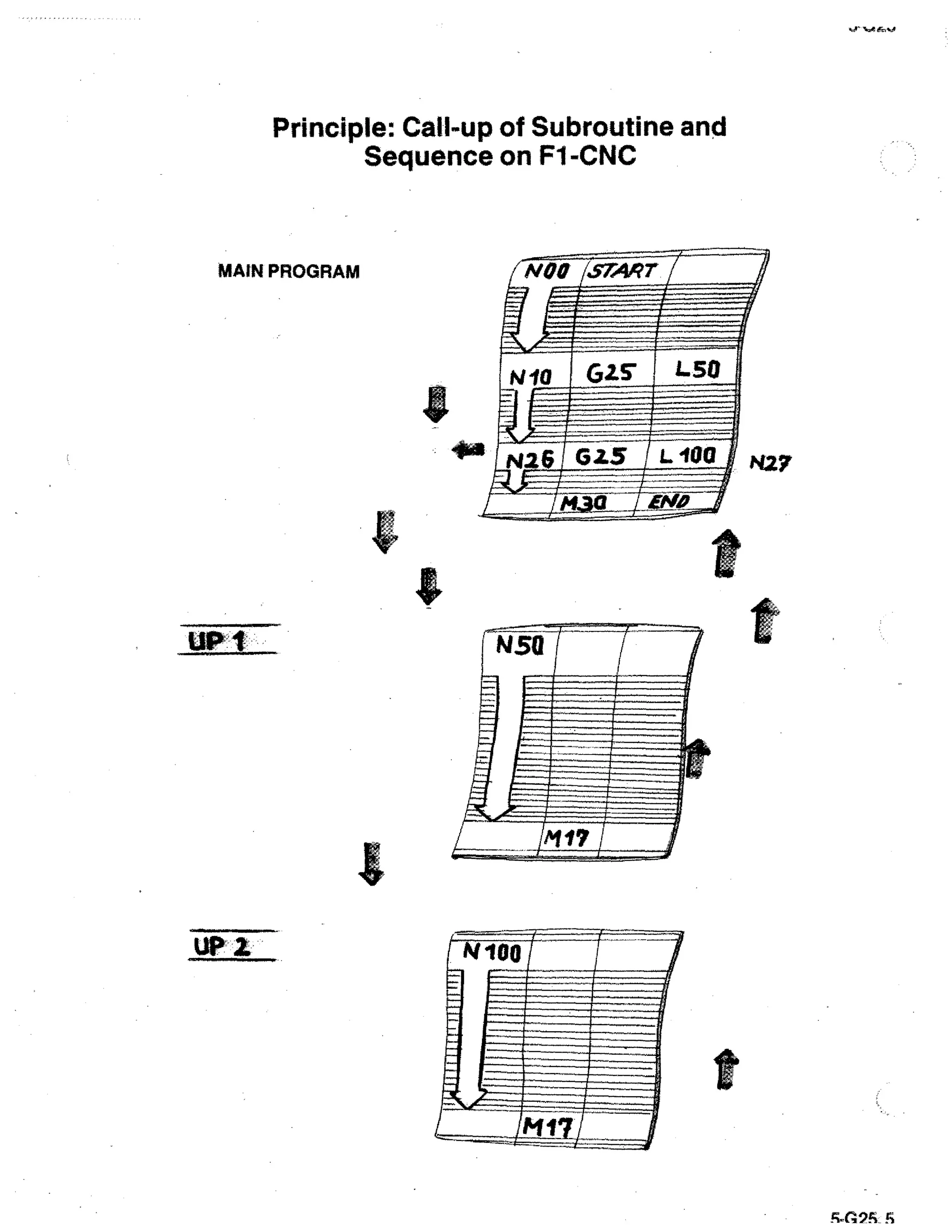
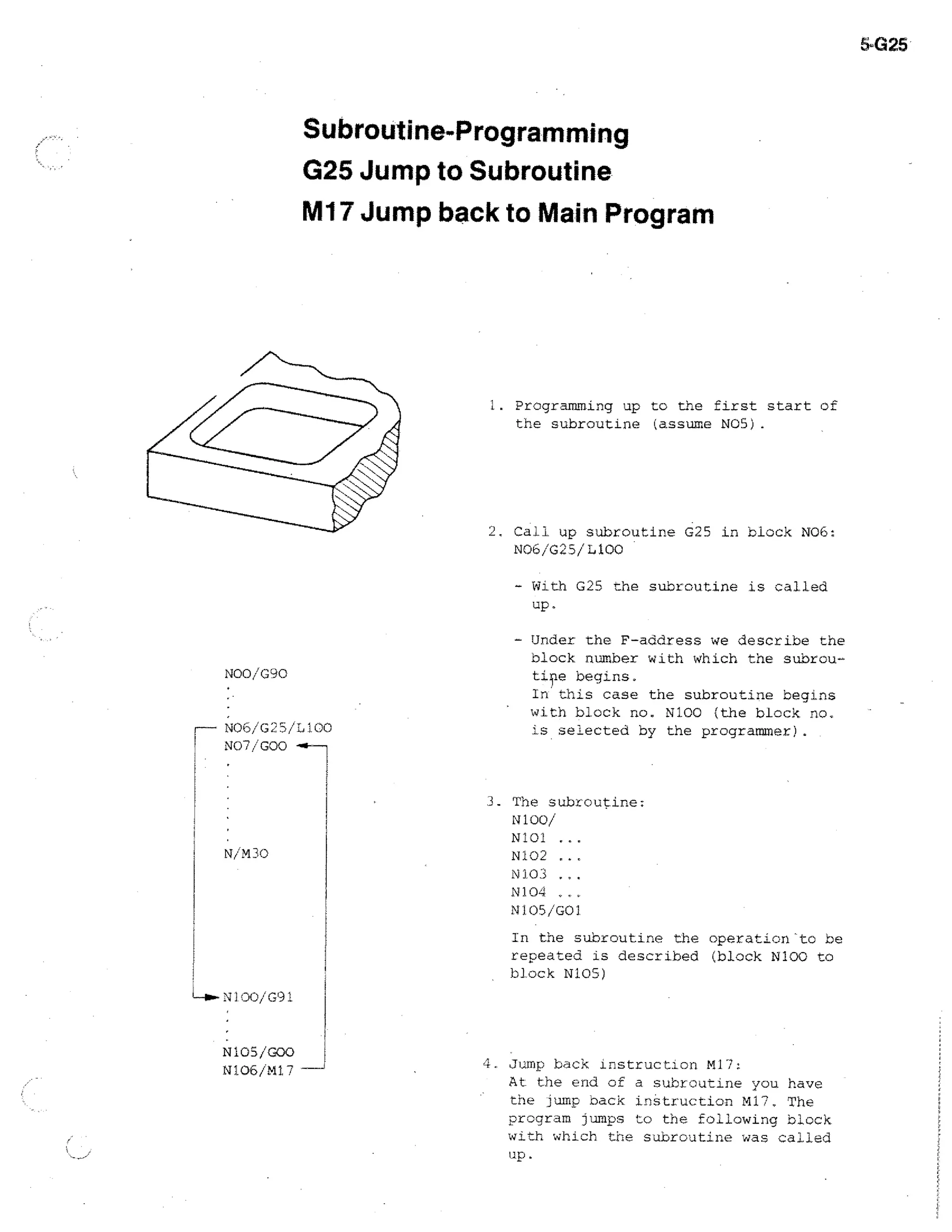
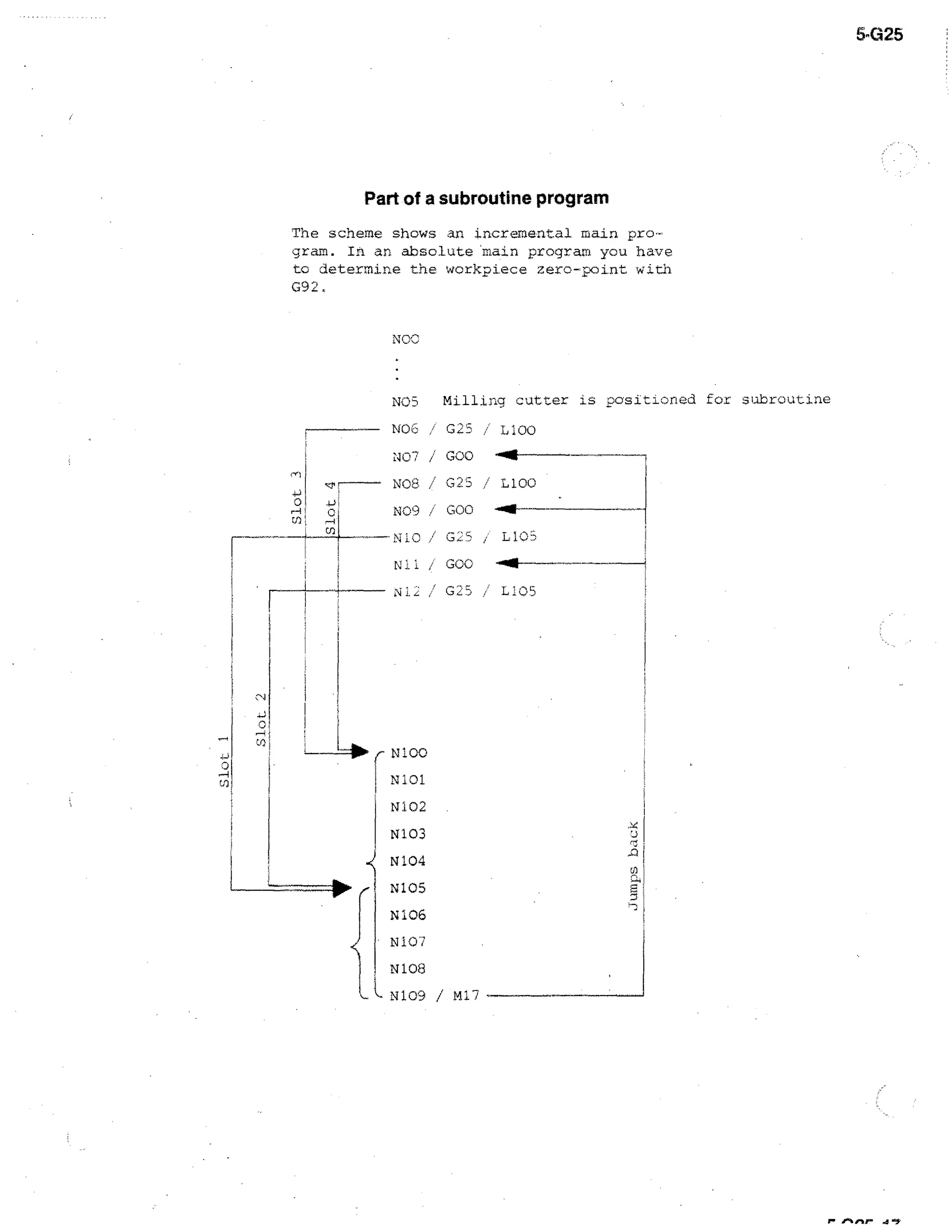
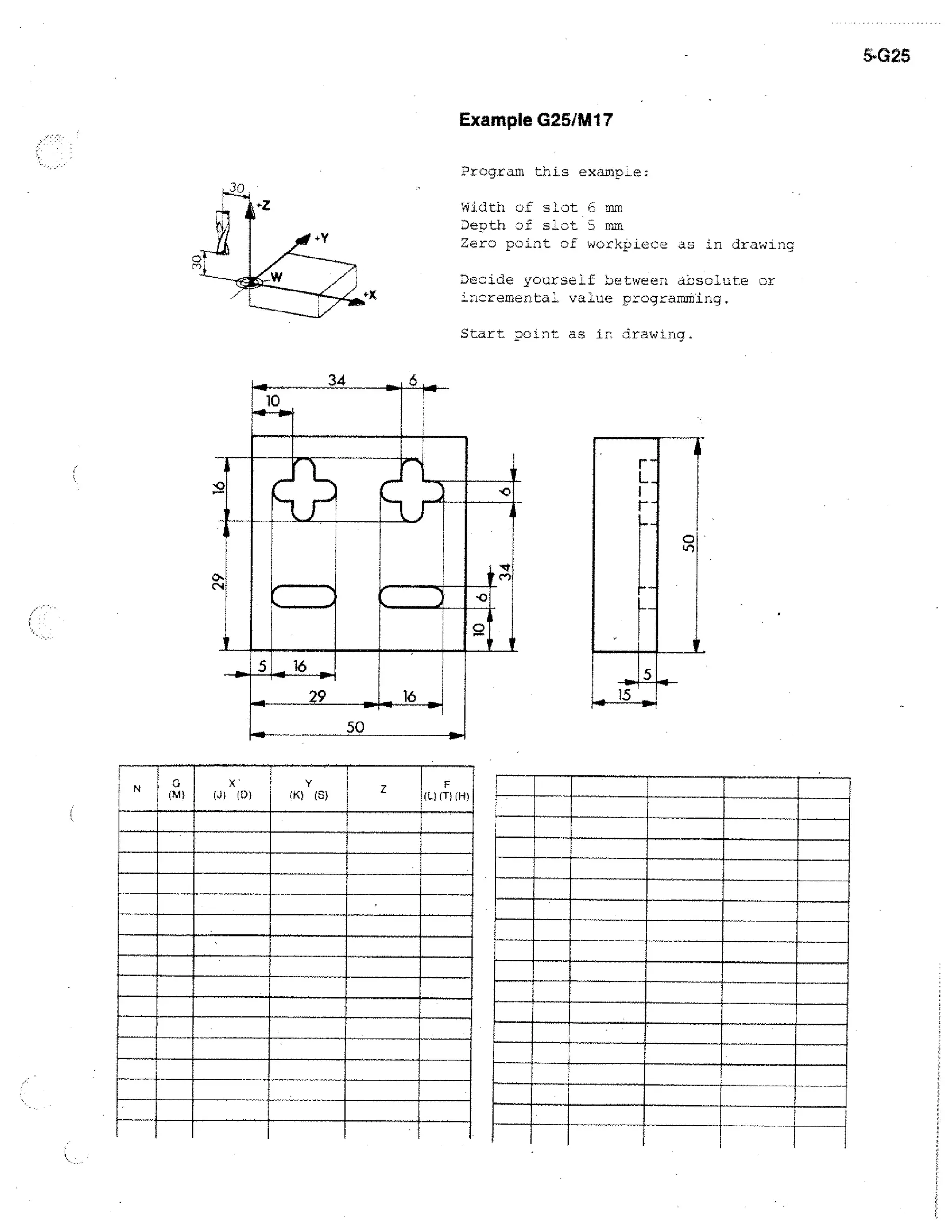
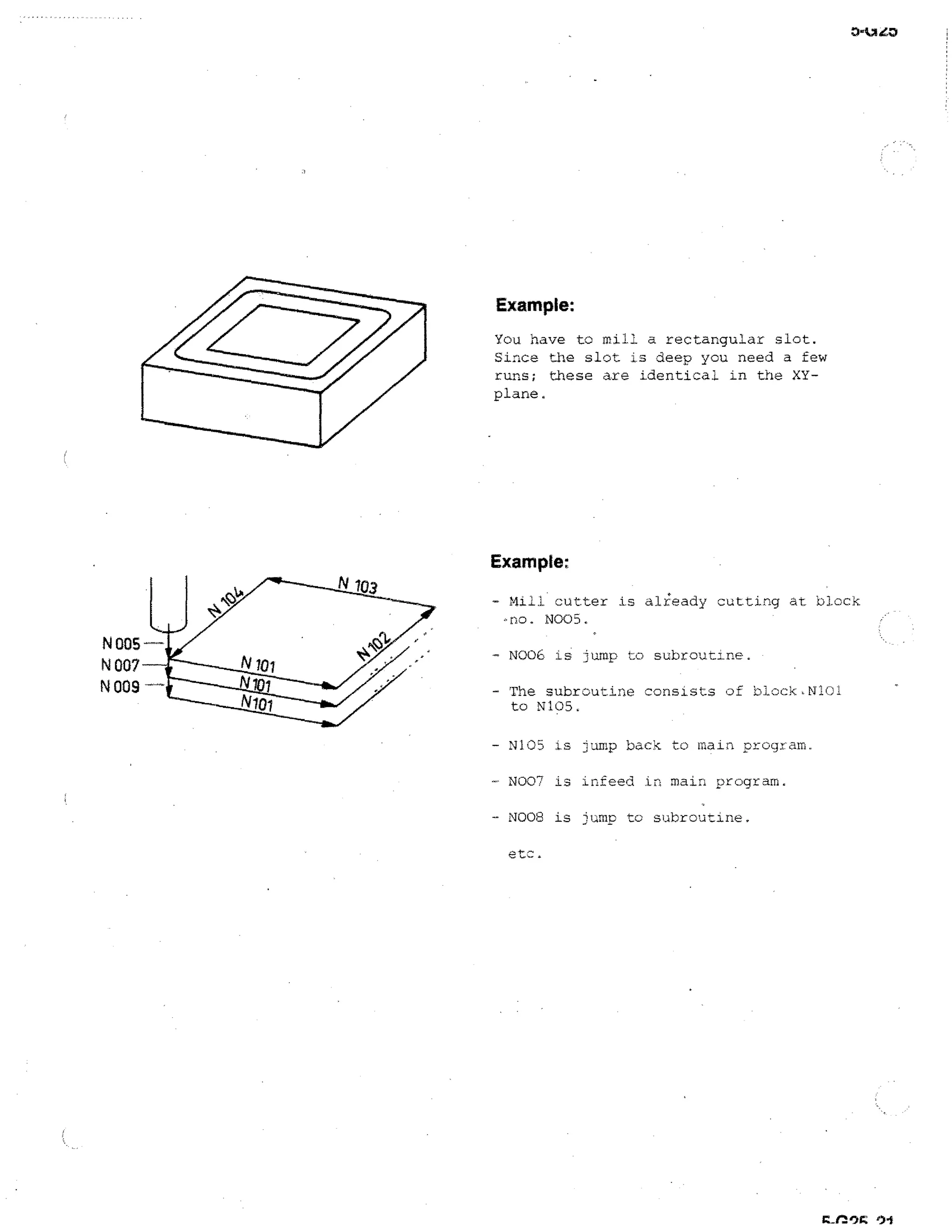
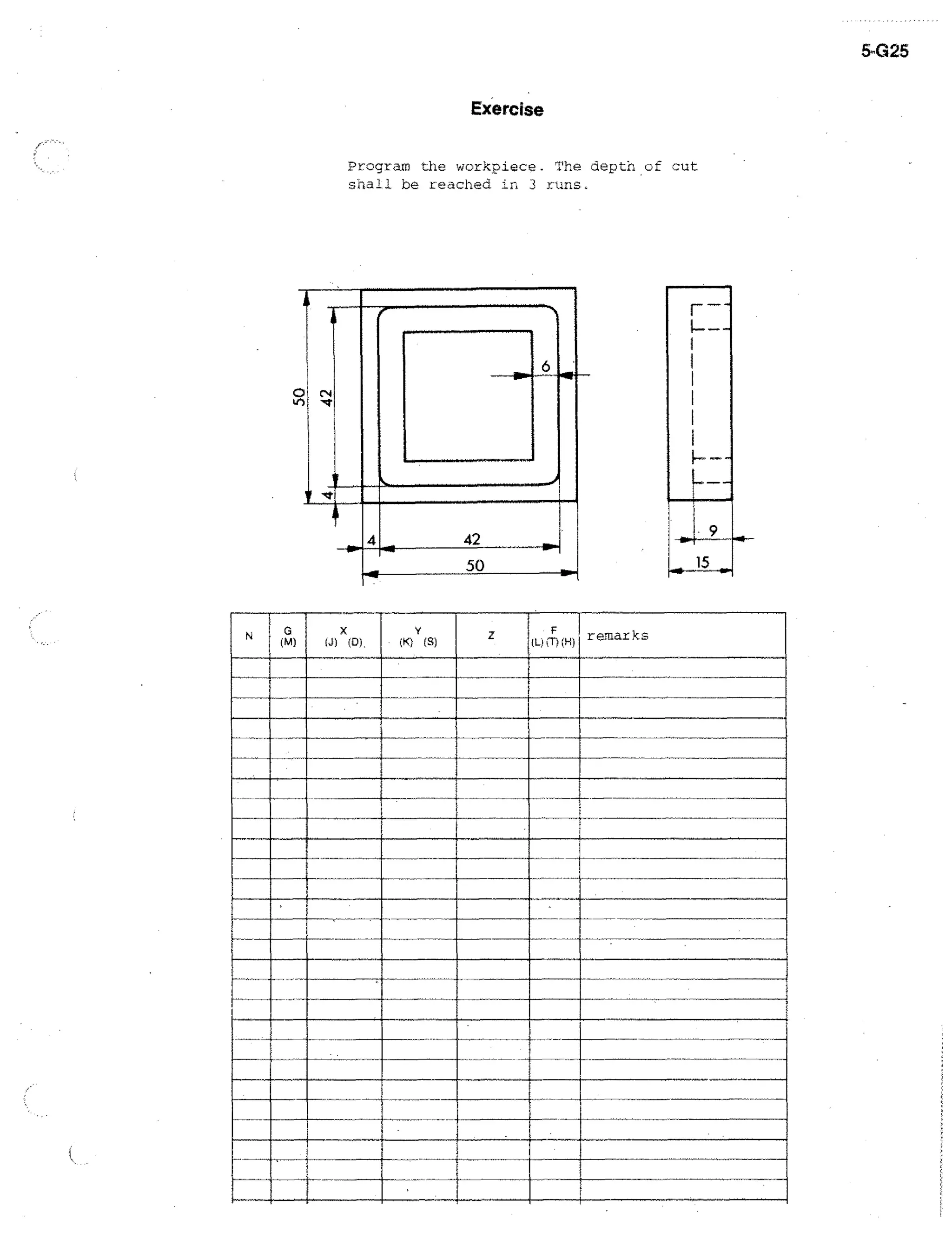
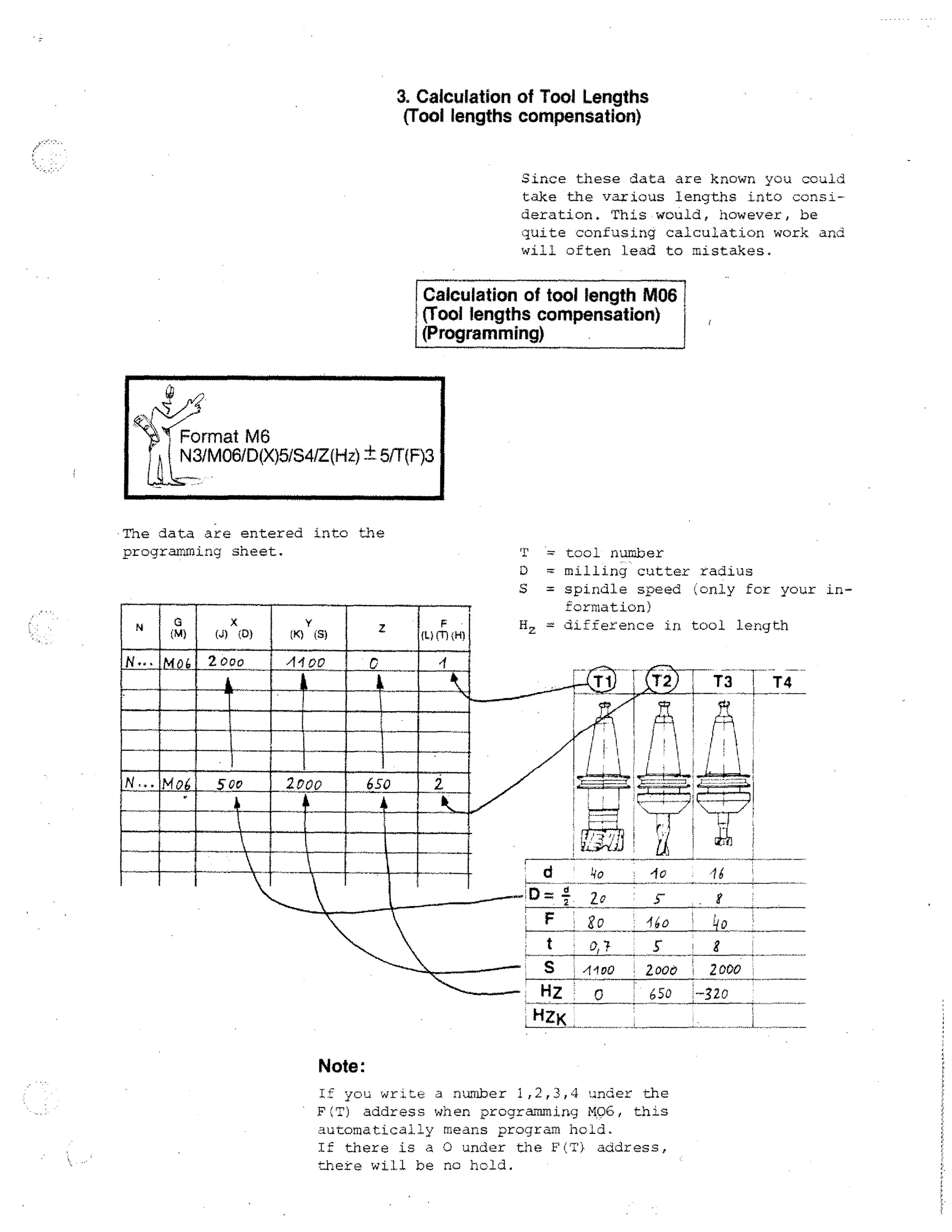
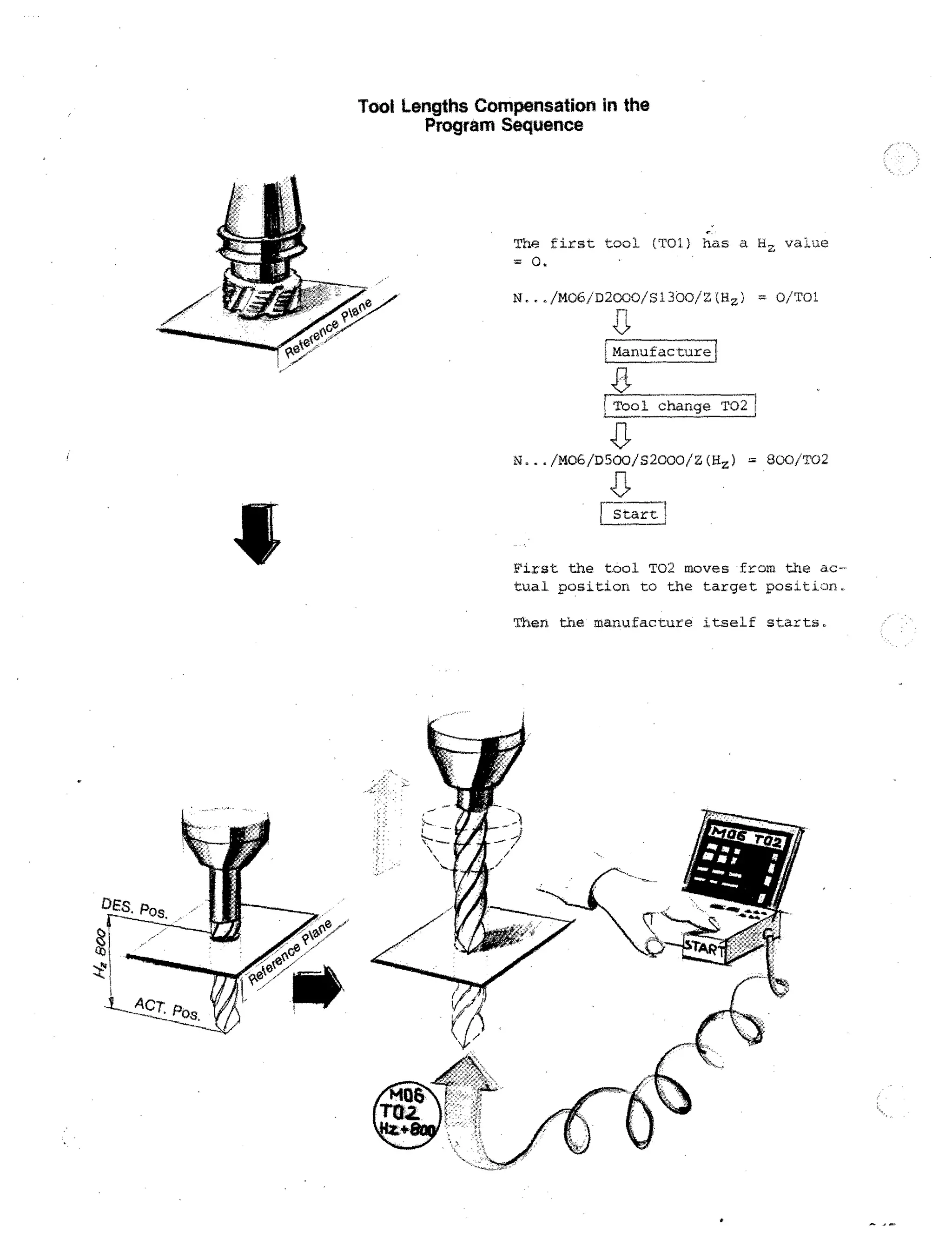
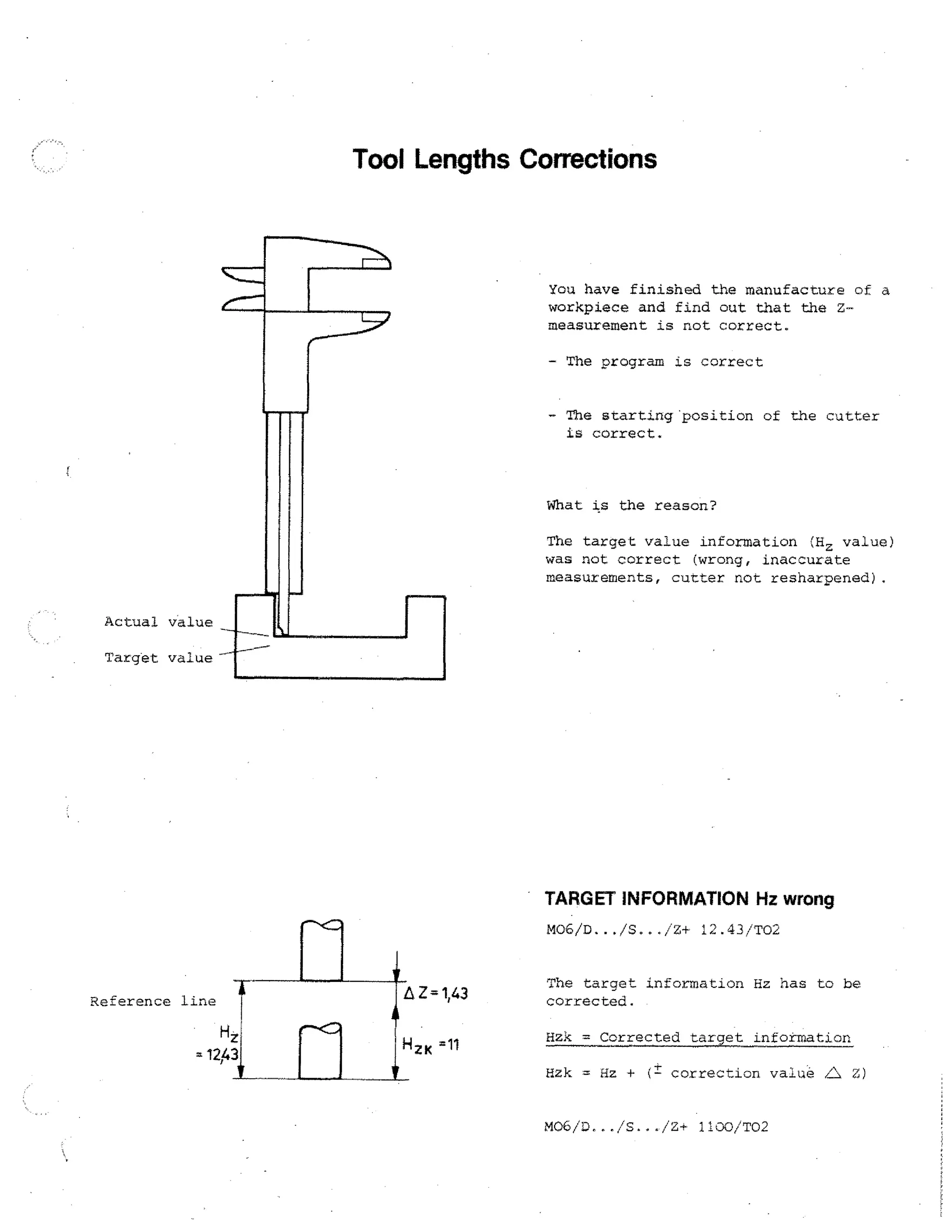
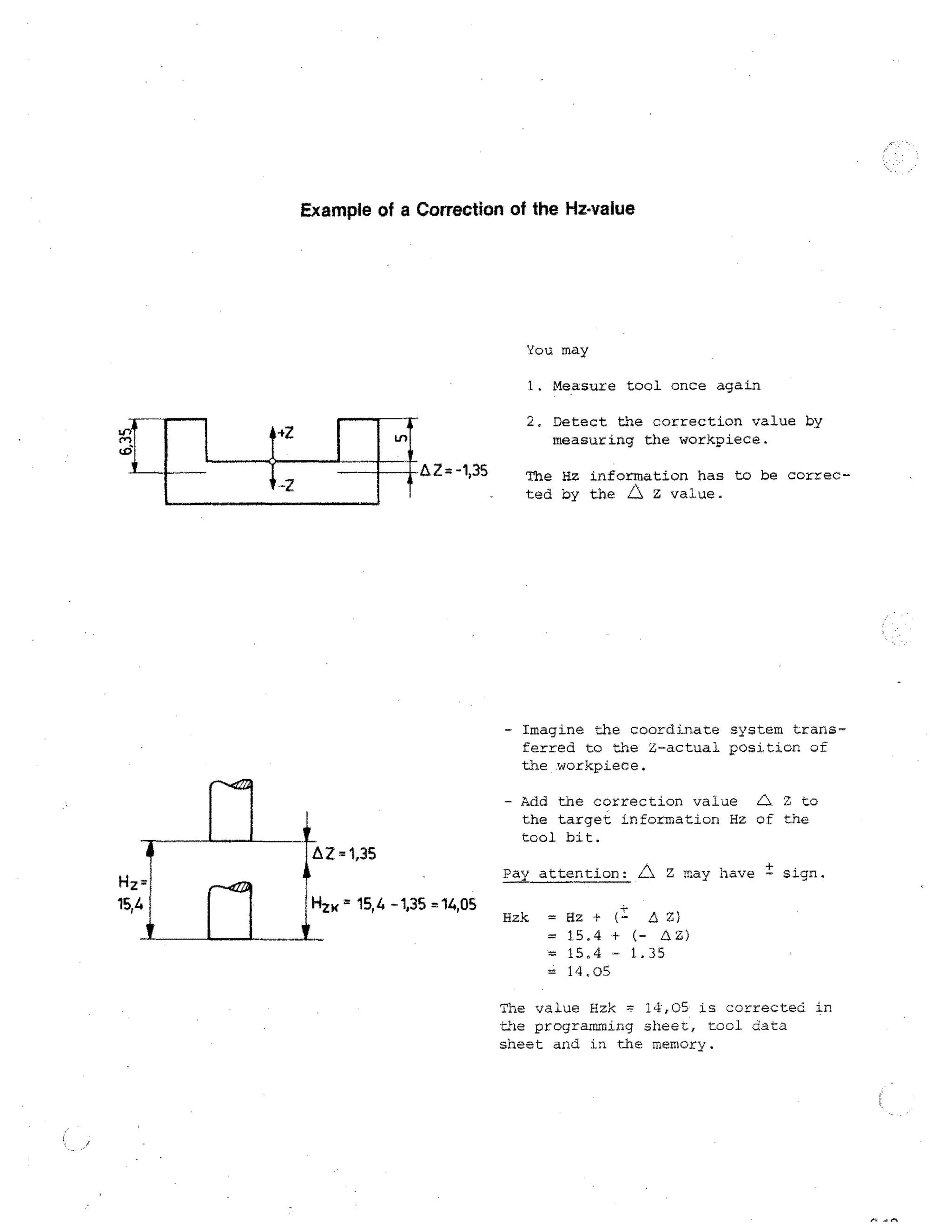
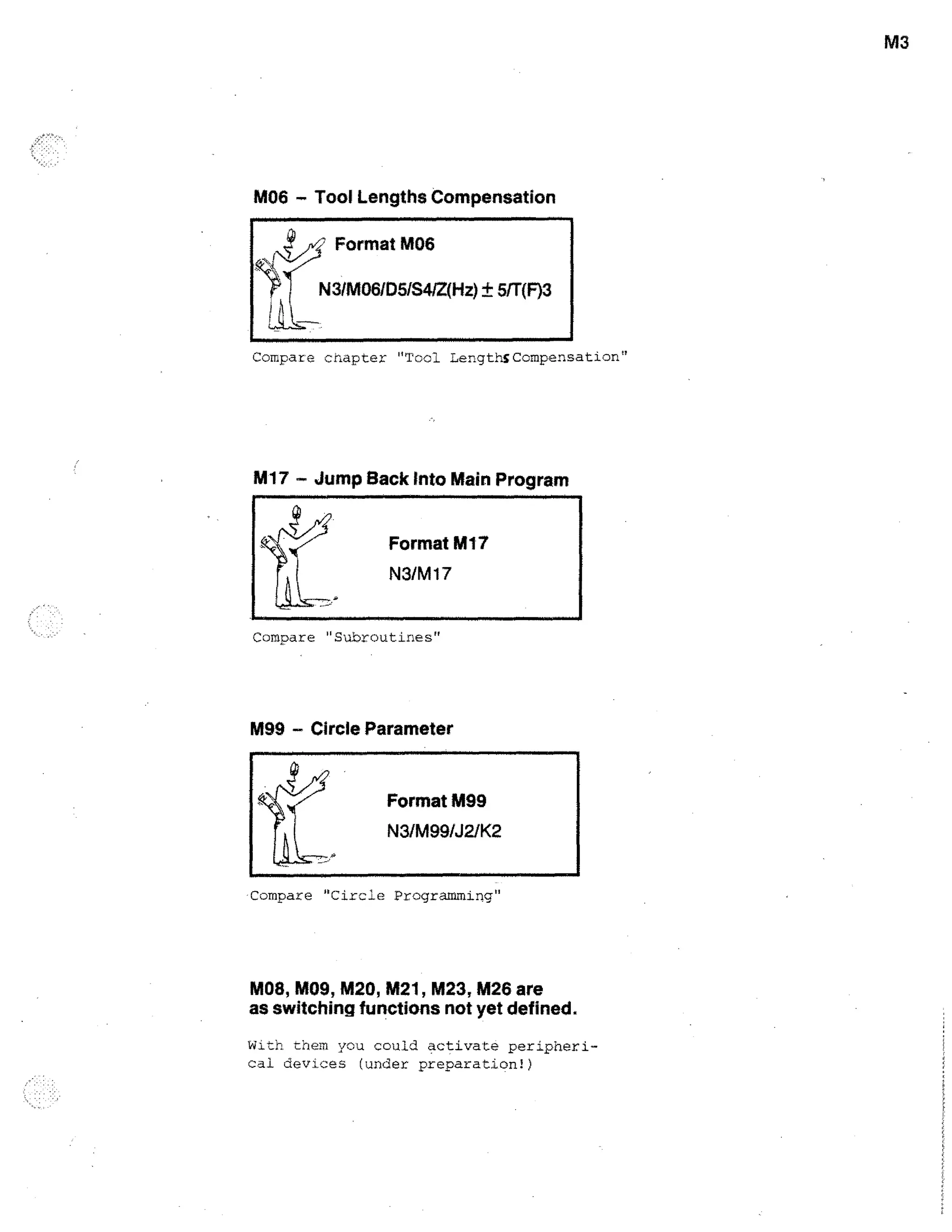
This document provides information about the EMCO F1-CNC machine for educational purposes. It discusses key aspects of operating and programming the CNC machine, including technological data for cutting speeds and feeds, tool clamping methods, workpiece clamping options, and use of the dividing attachment. The goal is for students to learn CNC techniques hands-on by working with the machine from the first lesson.


