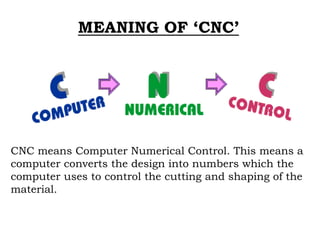
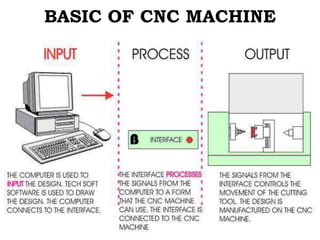
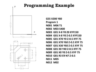
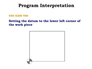
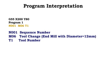
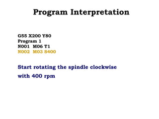
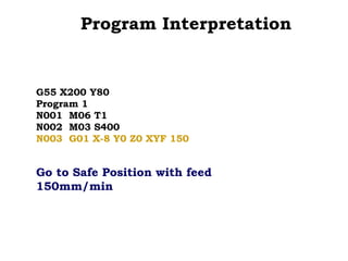
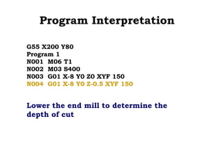
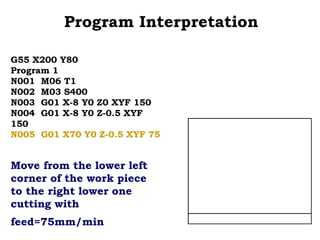
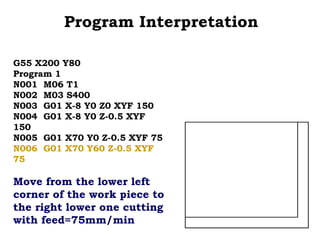
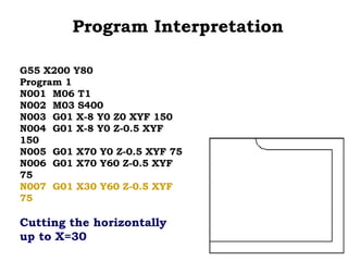
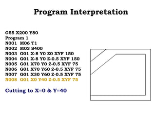
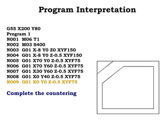
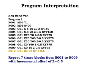
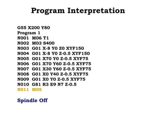
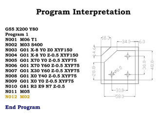
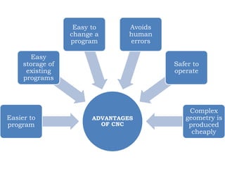
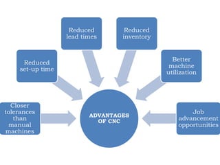
CNC Machine
(Computer Numerical Control M/c)
MEANING OF ‘CNC’
CNC means Computer Numerical Control. This means a
computer converts the design into numbers which the
computer uses to control the cutting and shaping of the
material.
BASIC OF CNC MACHINE
BASED ON MOTION
BASED ON CONTROL LOOPS
Open Loop
Closed Loop
BASED ON COORDINATE SYSTEM
a) Absolute System b) Incremental System
PROGRAMMING KEY LETTERS
• O - Program number (Used for program identification)
• N - Sequence number (Used for line identification)
• G - Preparatory function
• X - X axis designation
• Y - Y axis designation
• Z - Z axis designation
• R - Radius designation
• F – Feed rate designation
• S - Spindle speed designation
• H - Tool length offset designation
• D - Tool radius offset designation
• T - Tool Designation
• M - Miscellaneous function
FEATURES OF PROGRAMMING
N3 G2 X+1.4 Y+1.4 Z+1.4 I1.4 J1.4 K1.4 F3.2 S4 T4 M2
sequence
no
preparatory function
destination coordinates dist to center of circle
feed rate
spindle speed
tool
Other function
Sequence and format of words:
Raw Material Finished Part
Programming Example-1
Programming Example
G55 X200 Y80
Program 1
N001 M06 T1
N002 M03 S400
N003 G01 X-8 Y0 Z0 XYF150
N004 G01 X-8 Y0 Z-0.5 XYF150
N005 G01 X70 Y0 Z-0.5 XYF 75
N006 G01 X70 Y60 Z-0.5 XYF 75
N007 G01 X30 Y60 Z-0.5 XYF 75
N008 G01 X0 Y40 Z-0.5 XYF 75
N009 G01 X0 Y0 Z-0.5 XYF 75
N010 G81 R3 E9 N7 Z-0.5
N011 M05
N012 M02
x
y
Program Interpretation
G55 X200 Y80
Setting the datum to the lower left corner of
the work piece
Program Interpretation
G55 X200 Y80
Program 1
Program Identification Number
Program Interpretation
G55 X200 Y80
Program 1
N001 M06 T1
N001 Sequence Number
M06 Tool Change (End Mill with Diameter=12mm)
T1 Tool Number
Program Interpretation
G55 X200 Y80
Program 1
N001 M06 T1
N002 M03 S400
Start rotating the spindle clockwise
with 400 rpm
Program Interpretation
G55 X200 Y80
Program 1
N001 M06 T1
N002 M03 S400
N003 G01 X-8 Y0 Z0 XYF 150
Go to Safe Position with feed
150mm/min
Program Interpretation
G55 X200 Y80
Program 1
N001 M06 T1
N002 M03 S400
N003 G01 X-8 Y0 Z0 XYF 150
N004 G01 X-8 Y0 Z-0.5 XYF 150
Lower the end mill to determine the
depth of cut
Program Interpretation
G55 X200 Y80
Program 1
N001 M06 T1
N002 M03 S400
N003 G01 X-8 Y0 Z0 XYF 150
N004 G01 X-8 Y0 Z-0.5 XYF
150
N005 G01 X70 Y0 Z-0.5 XYF 75
Move from the lower left
corner of the work piece
to the right lower one
cutting with
feed=75mm/min
Program Interpretation
G55 X200 Y80
Program 1
N001 M06 T1
N002 M03 S400
N003 G01 X-8 Y0 Z0 XYF 150
N004 G01 X-8 Y0 Z-0.5 XYF
150
N005 G01 X70 Y0 Z-0.5 XYF 75
N006 G01 X70 Y60 Z-0.5 XYF
75
Move from the lower left
corner of the work piece to
the right lower one cutting
with feed=75mm/min
Program Interpretation
G55 X200 Y80
Program 1
N001 M06 T1
N002 M03 S400
N003 G01 X-8 Y0 Z0 XYF 150
N004 G01 X-8 Y0 Z-0.5 XYF
150
N005 G01 X70 Y0 Z-0.5 XYF 75
N006 G01 X70 Y60 Z-0.5 XYF
75
N007 G01 X30 Y60 Z-0.5 XYF
75
Cutting the horizontally
up to X=30
Program Interpretation
G55 X200 Y80
Program 1
N001 M06 T1
N002 M03 S400
N003 G01 X-8 Y0 Z0 XYF 150
N004 G01 X-8 Y0 Z-0.5 XYF 150
N005 G01 X70 Y0 Z-0.5 XYF 75
N006 G01 X70 Y60 Z-0.5 XYF 75
N007 G01 X30 Y60 Z-0.5 XYF 75
N008 G01 X0 Y40 Z-0.5 XYF 75
Cutting to X=0 & Y=40
Program Interpretation
G55 X200 Y80
Program 1
N001 M06 T1
N002 M03 S400
N003 G01 X-8 Y0 Z0 XYF150
N004 G01 X-8 Y0 Z-0.5 XYF150
N005 G01 X70 Y0 Z-0.5 XYF75
N006 G01 X70 Y60 Z-0.5 XYF75
N007 G01 X30 Y60 Z-0.5 XYF75
N008 G01 X0 Y40 Z-0.5 XYF75
N009 G01 X0 Y0 Z-0.5 XYF75
Complete the countering
Program Interpretation
G55 X200 Y80
Program 1
N001 M06 T1
N002 M03 S400
N003 G01 X-8 Y0 Z0 XYF150
N004 G01 X-8 Y0 Z-0.5 XYF150
N005 G01 X70 Y0 Z-0.5 XYF75
N006 G01 X70 Y60 Z-0.5 XYF75
N007 G01 X30 Y60 Z-0.5 XYF75
N008 G01 X0 Y40 Z-0.5 XYF75
N009 G01 X0 Y0 Z-0.5 XYF75
N010 G81 R3 E9 N7 Z-0.5
Repeat 7 times blocks from N003 to N009
with incremental offset of Z=-0.5
Program Interpretation
G55 X200 Y80
Program 1
N001 M06 T1
N002 M03 S400
N003 G01 X-8 Y0 Z0 XYF150
N004 G01 X-8 Y0 Z-0.5 XYF150
N005 G01 X70 Y0 Z-0.5 XYF75
N006 G01 X70 Y60 Z-0.5 XYF75
N007 G01 X30 Y60 Z-0.5 XYF75
N008 G01 X0 Y40 Z-0.5 XYF75
N009 G01 X0 Y0 Z-0.5 XYF75
N010 G81 R3 E9 N7 Z-0.5
N011 M05
Spindle Off
Program Interpretation
G55 X200 Y80
Program 1
N001 M06 T1
N002 M03 S400
N003 G01 X-8 Y0 Z0 XYF150
N004 G01 X-8 Y0 Z-0.5 XYF150
N005 G01 X70 Y0 Z-0.5 XYF75
N006 G01 X70 Y60 Z-0.5 XYF75
N007 G01 X30 Y60 Z-0.5 XYF75
N008 G01 X0 Y40 Z-0.5 XYF75
N009 G01 X0 Y0 Z-0.5 XYF75
N010 G81 R3 E9 N7 Z-0.5
N011 M05
N012 M02
End Program
ATC
(Automatic Tool Changer)
CNC Tooling
SINGLE ARM MECHANISM
CNC Tooling
PIVOT INSERTION MECHANISM
CNC Tooling
AUTOMATIC TOOL CHANGER
(ATC)
ADVANTAGES
OF CNC
Easier to
program
Easy
storage of
existing
programs
Easy to
change a
program
Avoids
human
errors
Safer to
operate
Complex
geometry is
produced
cheaply
ADVANTAGES
OF CNC
Closer
tolerances
than
manual
machines
Reduced
set-up time
Reduced
lead times
Reduced
inventory
Better
machine
utilization
Job
advancement
opportunities
Thank you

CNC

  • 1.
  • 3.
    MEANING OF ‘CNC’ CNCmeans Computer Numerical Control. This means a computer converts the design into numbers which the computer uses to control the cutting and shaping of the material.
  • 4.
    BASIC OF CNCMACHINE
  • 6.
  • 7.
    BASED ON CONTROLLOOPS Open Loop Closed Loop
  • 8.
    BASED ON COORDINATESYSTEM a) Absolute System b) Incremental System
  • 9.
    PROGRAMMING KEY LETTERS •O - Program number (Used for program identification) • N - Sequence number (Used for line identification) • G - Preparatory function • X - X axis designation • Y - Y axis designation • Z - Z axis designation • R - Radius designation • F – Feed rate designation • S - Spindle speed designation • H - Tool length offset designation • D - Tool radius offset designation • T - Tool Designation • M - Miscellaneous function
  • 10.
    FEATURES OF PROGRAMMING N3G2 X+1.4 Y+1.4 Z+1.4 I1.4 J1.4 K1.4 F3.2 S4 T4 M2 sequence no preparatory function destination coordinates dist to center of circle feed rate spindle speed tool Other function Sequence and format of words:
  • 11.
    Raw Material FinishedPart Programming Example-1
  • 12.
    Programming Example G55 X200Y80 Program 1 N001 M06 T1 N002 M03 S400 N003 G01 X-8 Y0 Z0 XYF150 N004 G01 X-8 Y0 Z-0.5 XYF150 N005 G01 X70 Y0 Z-0.5 XYF 75 N006 G01 X70 Y60 Z-0.5 XYF 75 N007 G01 X30 Y60 Z-0.5 XYF 75 N008 G01 X0 Y40 Z-0.5 XYF 75 N009 G01 X0 Y0 Z-0.5 XYF 75 N010 G81 R3 E9 N7 Z-0.5 N011 M05 N012 M02 x y
  • 13.
    Program Interpretation G55 X200Y80 Setting the datum to the lower left corner of the work piece
  • 14.
    Program Interpretation G55 X200Y80 Program 1 Program Identification Number
  • 15.
    Program Interpretation G55 X200Y80 Program 1 N001 M06 T1 N001 Sequence Number M06 Tool Change (End Mill with Diameter=12mm) T1 Tool Number
  • 16.
    Program Interpretation G55 X200Y80 Program 1 N001 M06 T1 N002 M03 S400 Start rotating the spindle clockwise with 400 rpm
  • 17.
    Program Interpretation G55 X200Y80 Program 1 N001 M06 T1 N002 M03 S400 N003 G01 X-8 Y0 Z0 XYF 150 Go to Safe Position with feed 150mm/min
  • 18.
    Program Interpretation G55 X200Y80 Program 1 N001 M06 T1 N002 M03 S400 N003 G01 X-8 Y0 Z0 XYF 150 N004 G01 X-8 Y0 Z-0.5 XYF 150 Lower the end mill to determine the depth of cut
  • 19.
    Program Interpretation G55 X200Y80 Program 1 N001 M06 T1 N002 M03 S400 N003 G01 X-8 Y0 Z0 XYF 150 N004 G01 X-8 Y0 Z-0.5 XYF 150 N005 G01 X70 Y0 Z-0.5 XYF 75 Move from the lower left corner of the work piece to the right lower one cutting with feed=75mm/min
  • 20.
    Program Interpretation G55 X200Y80 Program 1 N001 M06 T1 N002 M03 S400 N003 G01 X-8 Y0 Z0 XYF 150 N004 G01 X-8 Y0 Z-0.5 XYF 150 N005 G01 X70 Y0 Z-0.5 XYF 75 N006 G01 X70 Y60 Z-0.5 XYF 75 Move from the lower left corner of the work piece to the right lower one cutting with feed=75mm/min
  • 21.
    Program Interpretation G55 X200Y80 Program 1 N001 M06 T1 N002 M03 S400 N003 G01 X-8 Y0 Z0 XYF 150 N004 G01 X-8 Y0 Z-0.5 XYF 150 N005 G01 X70 Y0 Z-0.5 XYF 75 N006 G01 X70 Y60 Z-0.5 XYF 75 N007 G01 X30 Y60 Z-0.5 XYF 75 Cutting the horizontally up to X=30
  • 22.
    Program Interpretation G55 X200Y80 Program 1 N001 M06 T1 N002 M03 S400 N003 G01 X-8 Y0 Z0 XYF 150 N004 G01 X-8 Y0 Z-0.5 XYF 150 N005 G01 X70 Y0 Z-0.5 XYF 75 N006 G01 X70 Y60 Z-0.5 XYF 75 N007 G01 X30 Y60 Z-0.5 XYF 75 N008 G01 X0 Y40 Z-0.5 XYF 75 Cutting to X=0 & Y=40
  • 23.
    Program Interpretation G55 X200Y80 Program 1 N001 M06 T1 N002 M03 S400 N003 G01 X-8 Y0 Z0 XYF150 N004 G01 X-8 Y0 Z-0.5 XYF150 N005 G01 X70 Y0 Z-0.5 XYF75 N006 G01 X70 Y60 Z-0.5 XYF75 N007 G01 X30 Y60 Z-0.5 XYF75 N008 G01 X0 Y40 Z-0.5 XYF75 N009 G01 X0 Y0 Z-0.5 XYF75 Complete the countering
  • 24.
    Program Interpretation G55 X200Y80 Program 1 N001 M06 T1 N002 M03 S400 N003 G01 X-8 Y0 Z0 XYF150 N004 G01 X-8 Y0 Z-0.5 XYF150 N005 G01 X70 Y0 Z-0.5 XYF75 N006 G01 X70 Y60 Z-0.5 XYF75 N007 G01 X30 Y60 Z-0.5 XYF75 N008 G01 X0 Y40 Z-0.5 XYF75 N009 G01 X0 Y0 Z-0.5 XYF75 N010 G81 R3 E9 N7 Z-0.5 Repeat 7 times blocks from N003 to N009 with incremental offset of Z=-0.5
  • 25.
    Program Interpretation G55 X200Y80 Program 1 N001 M06 T1 N002 M03 S400 N003 G01 X-8 Y0 Z0 XYF150 N004 G01 X-8 Y0 Z-0.5 XYF150 N005 G01 X70 Y0 Z-0.5 XYF75 N006 G01 X70 Y60 Z-0.5 XYF75 N007 G01 X30 Y60 Z-0.5 XYF75 N008 G01 X0 Y40 Z-0.5 XYF75 N009 G01 X0 Y0 Z-0.5 XYF75 N010 G81 R3 E9 N7 Z-0.5 N011 M05 Spindle Off
  • 26.
    Program Interpretation G55 X200Y80 Program 1 N001 M06 T1 N002 M03 S400 N003 G01 X-8 Y0 Z0 XYF150 N004 G01 X-8 Y0 Z-0.5 XYF150 N005 G01 X70 Y0 Z-0.5 XYF75 N006 G01 X70 Y60 Z-0.5 XYF75 N007 G01 X30 Y60 Z-0.5 XYF75 N008 G01 X0 Y40 Z-0.5 XYF75 N009 G01 X0 Y0 Z-0.5 XYF75 N010 G81 R3 E9 N7 Z-0.5 N011 M05 N012 M02 End Program
  • 27.
  • 28.
  • 29.
  • 30.
  • 31.
    ADVANTAGES OF CNC Easier to program Easy storageof existing programs Easy to change a program Avoids human errors Safer to operate Complex geometry is produced cheaply
  • 32.
    ADVANTAGES OF CNC Closer tolerances than manual machines Reduced set-up time Reduced leadtimes Reduced inventory Better machine utilization Job advancement opportunities
  • 33.