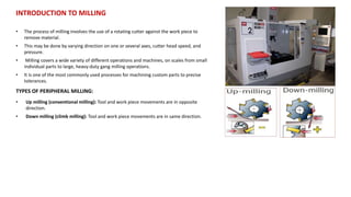
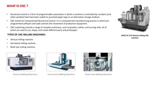
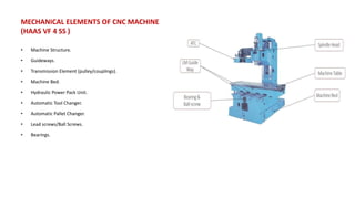
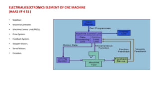
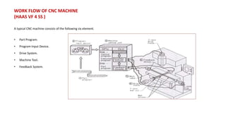
1) The document discusses CNC milling programming and machining, providing details on introductory concepts like types of milling, CNC machines, and elements of CNC machines.
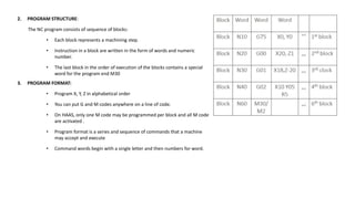
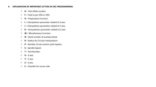
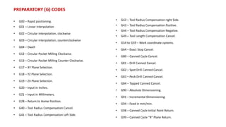
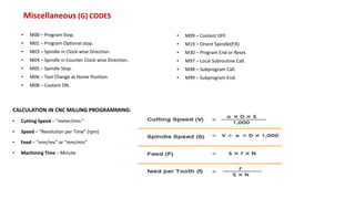
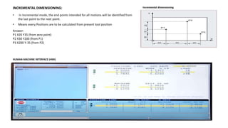
2) It explains key aspects of CNC programming like program structure and format, important codes like G and M codes, coordinate systems, and calculations.
3) Common CNC milling operations like facing, profiling, pocketing, and canned cycles for drilling are described along with advantages and applications of CNC machines.