The document discusses CNC machining and programming. It provides details on:
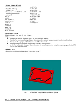
- Programming absolute, incremental, and polar G-code to machine slots, profiles, and holes on wood blocks using a CNC milling machine.
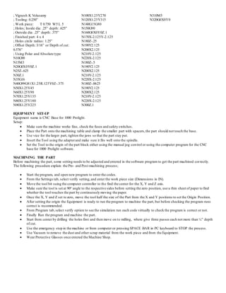
- The setup process for CNC machining including securing the workpiece, tool setup, establishing the coordinate system origin, and test running programs.
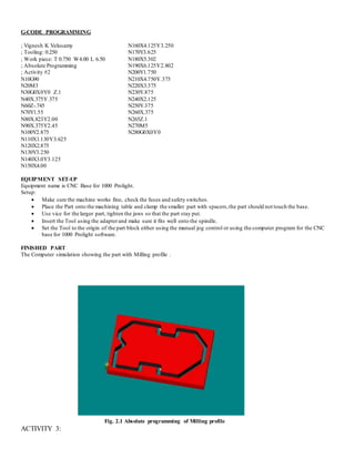
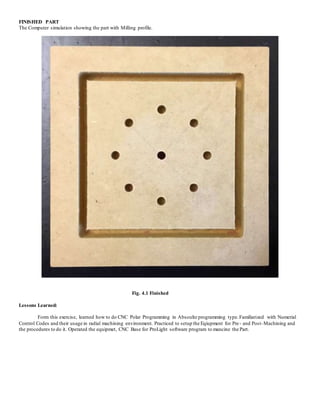
- Additional activities include milling profiles and holes using incremental programming, and milling circles of holes using polar and absolute programming.
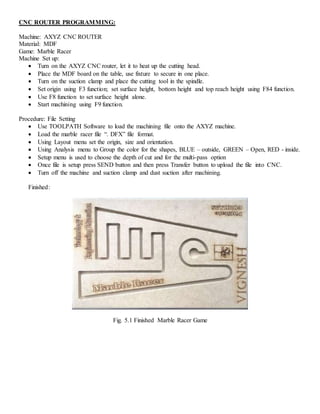
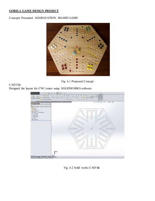
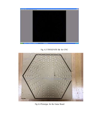
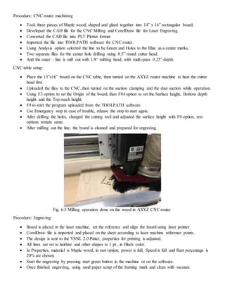
- The document also discusses a CNC router project to design a marble race game board using CAD software, converting the file for CNC, and laser engraving the design.