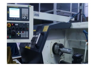
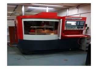
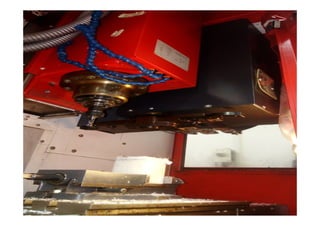
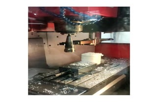
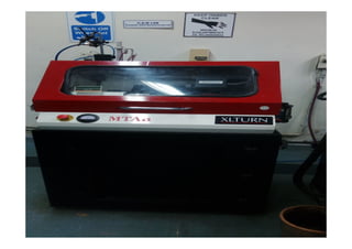
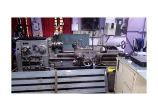
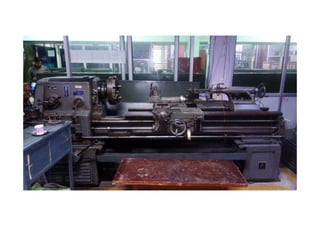
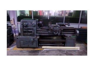
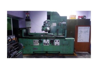
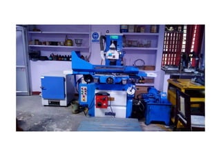
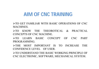
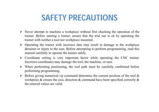
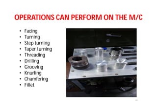
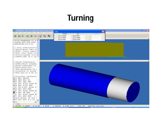
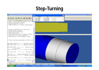
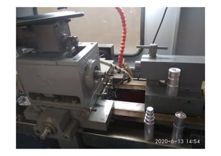
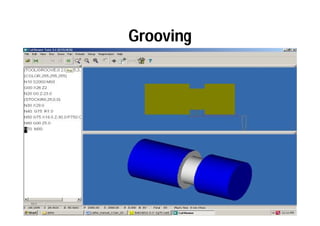
In House Summer Training
on
Introduction of CNC lathe machine
and
its operation
(Module 2)
Presented by: Mr. Dinesh Kumar
(AP/UCER)
Department of Mechanical Engineering
AIM OF CNC TRAINING
TO GET FAMILIAR WITH BASIC OPERATIONS OF CNC
MACHINES.
TO KNOW THE THEOROTICAL & PRACTICAL
CONCEPTS OF CNC MACHINE.
TO LEARN BASIC CONCEPT OF CNC PART
PROGRAMMING.
THE MOST IMPORTANT IS TO INCREASE THE
CONFIDENCE LEVEL OF USER.
TO UNDERSTAND THE BASIC WORKING PRINCIPLE OF
CNC ELECTRONIC, SOFTWARE, MECHANICAL SYSTEM.
Program Preparation Methods
Manual Programming (NC)
Computer Assisted Programming (CNC)
Advantages of CNC Machines
Elimination of operator error.
Lower labor cost.
Longer tool life.
Reduction in inspection & rejection.
High repeatability & accuracy.
Flexibility of machining various components.
SAFETY PRECAUTIONS
 Never attempt to machine a workpiece without first checking the operation of the
trainer. Before starting a trainer, ensure that the trial run is ok by operating the
trainer with neither a tool nor workpiece mounted.
 Operating the trainer with incorrect data may result in damage to the workpiece
&trainer or injury to the user. Before attempting to perform programming, read this
manual carefully to operate the trainer safely.
 Coordinate setting is very important factor while operating the CNC trainer.
Incorrect coordinates may damage the tool, the machine, or user.
 When performing positioning, the tool path must be carefully confirmed before
performing programming.
 Before giving numerical i/p command determine the current position of the tool &
workpiece & ensure the axis, direction & command have been specified correctly &
the entered values are valid.
CONTROL PANEL INDICATION
FRONT PANEL INDICATIONS &
SWITCHES INDICATIONS:
1. Emergency Stop (Red lamp)
This lamp will glow when somebody
presses the Emergency stop switch on
front panel. It indicates that there is
no power supply to the machine
motors & other circuit. If you run the
program you will get ‘Power Failure
‘message.
2. Spindle forward (Green lamp)
It will glow when the spindle is turned
ON to move in turned forward
direction through program or in JOG
mode.
CONTROL PANEL INDICATION
3. Spindle reverse (Green lamp)
It will glow when spindle rotates in anti-clockwise
direction.
4. Coolant ON (Green lamp)
When coolant motor is made ON through M07 or
M08 command, this lamp will glow.
5. LUB On ( Green Lamp)
This lamp glows when lubrication pump is ON.
X -TRIP (Red Lamp)
This lamp indicates that one of the limit switches of
the X-axis slide is operated.
6. Z- TRIP (Red Lamp)
Similar to above indication, if one of the limits switches
of Z axis is operated, this lamp will glow.
7. Mains ON (Red `ON’ lamp)
When the key switch is turned ON, this lamp will glow.
SWITCHES
1) Mains ON switch :
This switch is used to turn on the main supply. Now the
computer is to be started.
2) CNC ON Switch:
This switch will start the supply to the stepper motor,
Spindle motor & other electronic circuits. But
remember to switch ON this only after the PC is
started.
3) Machine Lamp Switch:
This will start the lamp on the machine.
4) Emergency Stop Switch (Red colored):
This is a Press-To-Lock switch. These will cut-off the
machines supply but the computer will not be off.
Features of Windows based CNC-
LATHE software
1) Powerful Graphic user interface.
2) All the programming codes are compatible to the Fanuc.nc0
Model.
3) On-line 2-D & 3-D simulation
4) On-line program Editing facility.
5) Software based Spindle speed over-ride & Feed over-ride.
6) Program execution in Auto, Single Block & Selected Block
mode.
7) Print option with 2-D simulation & program.
8) Automatic calculation for G02 & G03 codes.
9) On line programming help facility.
CUTVIEWER TURN SOFTWARE
What is CutViewer Turn?
Cutviewer Turn V3.1 is an easy to use program that graphically displays the material
removal process for turning operations in 2 axes. Based on the stock statements and
tool definitions, Cutviewer will show you exactly what material will be removed from
a raw stock.
What Hardware does CutViewer Require?
CutViewer is a 32 bit application. It runs in Windows 95/98/ME/NT/2000/XP. The
hardware minimums include a Pentium processor, 32 MB of RAM, 20 MB of hard
disk space, and a video graphics card with at least 2 MB of video RAM. Display
Settings before running CutViewer, set the Windows Color Palette to 16- bit mode
(65535 colors) or higher. The raw stock can be defined as either a simple cylinder or a
free shape stock. Stock and tool data can be included in your NC program, or defined
separately prior to running the program.
This version supports the following types of tools:
• Standard tools
• Button tools
• Grooving tools
Tool Geometry
OPERATIONS CAN PERFORM ON THE M/C
• Facing
• Turning
• Step turning
• Taper turning
• Threading
• Drilling
• Grooving
• Knurling
• Chamfering
• Fillet
34
Facing
• Facing Operations. Facing is the process of
removing metal from the end of a workpiece
to produce a flat surface.
Facing
Turning
• Turning Operations. Turning is the removal of
metal from the outer diameter of a rotating
cylindrical workpiece. Turning is used to
reduce the diameter of the workpiece, usually
to a specified dimension, and to produce a
smooth finish on the metal.
Turning
Step- Turning
• Step turning is an operation performed
on lathe machine where the excess material is
removed from the work piece to obtain
various steps of different diameters.
Step-Turning
Taper Turning
• Taper turning. When the diameter of a piece
changes uniformly from one end to the other,
the piece is said to be tapered. Taper
turning as a machining operation is the
gradual reduction in diameter from one part
of a cylindrical workpiece to another
part.Tapers can be either external or internal.
Taper Turning
Threading
• Threading is the process of creating a
screw thread.
or
• Thread cutting on the lathe is a process that
produces a helical ridge of uniform section on
the workpiece. This is performed by taking
successive cuts with a threading tool bit the
same shape as the thread form required.
Threading
Drilling
• Drilling is a cutting process that uses
a drill bit to cut a hole of circular cross-
section in solid materials. The drill bit is
usually a rotary cutting tool, often multi-point.
The bit is pressed against the work-piece and
rotated at rates from hundreds to thousands
of revolutions per minute.
Drilling
Grooving
• Groove cutting on CNC lathes is a multi step
machining operation.
• The term grooving usually applies to
a process of forming a narrow cavity of a
certain depth, on a cylinder, cone, or a face of
the part. The groove shape, or at least a
significant part of it, will be in the shape of the
cutting tool.
Grooving
Knurling
• Knurling is a process of impressing a diamond
shaped or straight line pattern into the surface
of a workpiece by using specially shaped
hardened metal wheels to improve its
appearance and to provide a better gripping
surface.
Chamfering
• Chamfering is the operation of beveling the
extreme end of the work piece. The form tool
used for taper turning may be used for this
purpose. Chamfering is an
essential operation after thread cutting so
that the nut may pass freely on the threaded
work piece.
Fillet
• First, a terminology review: in design and
machining, a chamfer is a sloped or angled
corner or edge, and a fillet is a rounded corner
or edge. These edges can be located on either
the interior or the exterior of a part
Multi Operation
? 59

Lecture 1

  • 1.
    In House SummerTraining on
  • 6.
    Introduction of CNClathe machine and its operation (Module 2) Presented by: Mr. Dinesh Kumar (AP/UCER) Department of Mechanical Engineering
  • 18.
    AIM OF CNCTRAINING TO GET FAMILIAR WITH BASIC OPERATIONS OF CNC MACHINES. TO KNOW THE THEOROTICAL & PRACTICAL CONCEPTS OF CNC MACHINE. TO LEARN BASIC CONCEPT OF CNC PART PROGRAMMING. THE MOST IMPORTANT IS TO INCREASE THE CONFIDENCE LEVEL OF USER. TO UNDERSTAND THE BASIC WORKING PRINCIPLE OF CNC ELECTRONIC, SOFTWARE, MECHANICAL SYSTEM.
  • 23.
    Program Preparation Methods ManualProgramming (NC) Computer Assisted Programming (CNC)
  • 24.
    Advantages of CNCMachines Elimination of operator error. Lower labor cost. Longer tool life. Reduction in inspection & rejection. High repeatability & accuracy. Flexibility of machining various components.
  • 25.
    SAFETY PRECAUTIONS  Neverattempt to machine a workpiece without first checking the operation of the trainer. Before starting a trainer, ensure that the trial run is ok by operating the trainer with neither a tool nor workpiece mounted.  Operating the trainer with incorrect data may result in damage to the workpiece &trainer or injury to the user. Before attempting to perform programming, read this manual carefully to operate the trainer safely.  Coordinate setting is very important factor while operating the CNC trainer. Incorrect coordinates may damage the tool, the machine, or user.  When performing positioning, the tool path must be carefully confirmed before performing programming.  Before giving numerical i/p command determine the current position of the tool & workpiece & ensure the axis, direction & command have been specified correctly & the entered values are valid.
  • 26.
    CONTROL PANEL INDICATION FRONTPANEL INDICATIONS & SWITCHES INDICATIONS: 1. Emergency Stop (Red lamp) This lamp will glow when somebody presses the Emergency stop switch on front panel. It indicates that there is no power supply to the machine motors & other circuit. If you run the program you will get ‘Power Failure ‘message. 2. Spindle forward (Green lamp) It will glow when the spindle is turned ON to move in turned forward direction through program or in JOG mode.
  • 27.
    CONTROL PANEL INDICATION 3.Spindle reverse (Green lamp) It will glow when spindle rotates in anti-clockwise direction. 4. Coolant ON (Green lamp) When coolant motor is made ON through M07 or M08 command, this lamp will glow. 5. LUB On ( Green Lamp) This lamp glows when lubrication pump is ON. X -TRIP (Red Lamp) This lamp indicates that one of the limit switches of the X-axis slide is operated. 6. Z- TRIP (Red Lamp) Similar to above indication, if one of the limits switches of Z axis is operated, this lamp will glow. 7. Mains ON (Red `ON’ lamp) When the key switch is turned ON, this lamp will glow.
  • 28.
    SWITCHES 1) Mains ONswitch : This switch is used to turn on the main supply. Now the computer is to be started. 2) CNC ON Switch: This switch will start the supply to the stepper motor, Spindle motor & other electronic circuits. But remember to switch ON this only after the PC is started. 3) Machine Lamp Switch: This will start the lamp on the machine. 4) Emergency Stop Switch (Red colored): This is a Press-To-Lock switch. These will cut-off the machines supply but the computer will not be off.
  • 29.
    Features of Windowsbased CNC- LATHE software 1) Powerful Graphic user interface. 2) All the programming codes are compatible to the Fanuc.nc0 Model. 3) On-line 2-D & 3-D simulation 4) On-line program Editing facility. 5) Software based Spindle speed over-ride & Feed over-ride. 6) Program execution in Auto, Single Block & Selected Block mode. 7) Print option with 2-D simulation & program. 8) Automatic calculation for G02 & G03 codes. 9) On line programming help facility.
  • 30.
    CUTVIEWER TURN SOFTWARE Whatis CutViewer Turn? Cutviewer Turn V3.1 is an easy to use program that graphically displays the material removal process for turning operations in 2 axes. Based on the stock statements and tool definitions, Cutviewer will show you exactly what material will be removed from a raw stock. What Hardware does CutViewer Require? CutViewer is a 32 bit application. It runs in Windows 95/98/ME/NT/2000/XP. The hardware minimums include a Pentium processor, 32 MB of RAM, 20 MB of hard disk space, and a video graphics card with at least 2 MB of video RAM. Display Settings before running CutViewer, set the Windows Color Palette to 16- bit mode (65535 colors) or higher. The raw stock can be defined as either a simple cylinder or a free shape stock. Stock and tool data can be included in your NC program, or defined separately prior to running the program. This version supports the following types of tools: • Standard tools • Button tools • Grooving tools
  • 32.
  • 34.
    OPERATIONS CAN PERFORMON THE M/C • Facing • Turning • Step turning • Taper turning • Threading • Drilling • Grooving • Knurling • Chamfering • Fillet 34
  • 35.
    Facing • Facing Operations.Facing is the process of removing metal from the end of a workpiece to produce a flat surface.
  • 36.
  • 37.
    Turning • Turning Operations.Turning is the removal of metal from the outer diameter of a rotating cylindrical workpiece. Turning is used to reduce the diameter of the workpiece, usually to a specified dimension, and to produce a smooth finish on the metal.
  • 38.
  • 39.
    Step- Turning • Stepturning is an operation performed on lathe machine where the excess material is removed from the work piece to obtain various steps of different diameters.
  • 40.
  • 42.
    Taper Turning • Taperturning. When the diameter of a piece changes uniformly from one end to the other, the piece is said to be tapered. Taper turning as a machining operation is the gradual reduction in diameter from one part of a cylindrical workpiece to another part.Tapers can be either external or internal.
  • 43.
  • 44.
    Threading • Threading isthe process of creating a screw thread. or • Thread cutting on the lathe is a process that produces a helical ridge of uniform section on the workpiece. This is performed by taking successive cuts with a threading tool bit the same shape as the thread form required.
  • 45.
  • 47.
    Drilling • Drilling isa cutting process that uses a drill bit to cut a hole of circular cross- section in solid materials. The drill bit is usually a rotary cutting tool, often multi-point. The bit is pressed against the work-piece and rotated at rates from hundreds to thousands of revolutions per minute.
  • 48.
  • 49.
    Grooving • Groove cuttingon CNC lathes is a multi step machining operation. • The term grooving usually applies to a process of forming a narrow cavity of a certain depth, on a cylinder, cone, or a face of the part. The groove shape, or at least a significant part of it, will be in the shape of the cutting tool.
  • 50.
  • 51.
    Knurling • Knurling isa process of impressing a diamond shaped or straight line pattern into the surface of a workpiece by using specially shaped hardened metal wheels to improve its appearance and to provide a better gripping surface.
  • 53.
    Chamfering • Chamfering isthe operation of beveling the extreme end of the work piece. The form tool used for taper turning may be used for this purpose. Chamfering is an essential operation after thread cutting so that the nut may pass freely on the threaded work piece.
  • 55.
    Fillet • First, aterminology review: in design and machining, a chamfer is a sloped or angled corner or edge, and a fillet is a rounded corner or edge. These edges can be located on either the interior or the exterior of a part
  • 58.
  • 59.