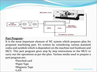
UNIT5 – Numerical Control
®Educational Purpose Only
Numerical Control (NC) or control by numbers, is the concept,
which has revolutionized the manufacturing scene that is partially
due to the rapid advancement in microelectronics that has taken
place since late 1960’s.
Numerical control of machine tools may be defined as a method
of automation in which various functions of machine tools are
controlled by letters, numbers and symbols.
In NC machine tools one or more of the following functions may
be automatic:
a) starting and stopping of machine tool spindle
b) controlling the spindle speed
c) positioning the tool tip at desired locations and guiding it along
desired paths by automatic control of the motion of slides
d) controlling the rate of movement of the tool tip (i.e. feed rate)
e) changing of tools in the spindle.
®Educational Purpose Only
Basic CNC Principles
All computer controlled machines are able to accurately and
repeatedly control motion in various directions. Each of these
directions of motion is called an axis. Depending on the machine type
there are commonly two to five axes.
Additionally, a CNC axis may be either a linear axis in which movement
is in a straight line, or a rotary axis with motion following a circular
path.
Basic CNC Principles Coordinates System
Basic CNC Principles
 Using a vertical mill
machining center as an
example, there are typically
three linear axes of motion.
Each is given an alphabetic
designation or address.
 The machine table motion
side to side is called the “X”
axis. Table movement in
and out is the “Y” axis,
while head movement up
and down the column is
the “Z” axis.
®Educational Purpose Only
Part Program:-
It is the most important element of NC system which prepares plan for
proposed machining part. It’s written by considering various standard
codes and symbols which is dependent on the machine tool hardware and
MCU. This part program gives step by step instructions to the MCU to
carry out the operations as per the plan. Various media used to prepare a
part program are:
•Punched card
•Paper Tape
•Magnetic Tape
•LAN
®Educational Purpose Only
MCU:-
MCU consists of the electronics and hardware system which is either
fitted to machine tool or may be housed in a separately standing cabinet.
Coded part program is used by MCU to control and position the cutting
tool and work piece. It acts as a brain of NC machine and it reads,
interprets and converts input into appropriate movement of slides. It also
controls various non-machining operations like tool change, coolant
on/off, loading/unloading of part etc.
The machine control unit includes – Data Processing Unit (DPU) and
control loop unit (CLU). DPU reads the part program, decodes it,
processes the information and passes it to CLU. Control Loop Unit
converts the information to control signals and drives the mechanism,
receives feedback and instructs DPU to read new instructions.
The numbers of CNC controller are available such as FANUC,
Siemens, Cincinnati, Sinumerik, Eluct, Japax, Supercut, Bosch, Philips,
Toshiba etc.
®Educational Purpose Only
Diagram for feedback system for a machine tool axis
(modified from Braasch 2002b)
®Educational Purpose Only
VM182 measurement set-up for Mitsui Seiki
NC Machine Tools are used ;
1.For the parts having complex contours, that cannot be
manufactured by conventional machine tools.
2.For small lot production, often for even single (one off) job
production, such as for prototyping, tool manufacturing, etc…
3. For jobs requiring very high accuracy and repeatability.
4. For jobs requiring many set-ups and/or the setups very expensive.
5.The parts that are subjected to frequent design changes and
consequently require more expensive manufacturing methods.
6.The inspection cost is a significant portion of the total
manufacturing cost.
®Educational Purpose Only
1. Based on Type of Machine
2. Based on Programming
(a)Absolute Programming
(b)Incremental Programming
3. Based on Type of Control Structure
(a) NC
(b) CNC
4. Based on Type of control loop
Manual Part programming
Block Format
N____ G__ X_ Y_ Z_Xc__ Yc__ S_ F_ T__ R___ M_
STEPS in NC Program
1. %
2. Part Number
3. Tool specification
4. Type of programming (Abs/Inc)
5. Offset, Tool change
6. Goto starting Point (0,0) – Rapid traverse
7. Spindle on, coolant on
8. Actual machining with geometry
:
:
:
9. Rapid Traverse to (Z 150), spindle off, coolant off
10. Repeat steps 5 to 9, if any machining operations left.
11. Cancellation of cycles
12.Everything will switched off
Programming Key Letters
 O - Program number (Used for program identification)
 N - Sequence number (Used for line identification)
 G - Preparatory function
 X - X axis designation
 Y - Y axis designation
 Z - Z axis designation
 R - Radius designation
 F – Feed rate designation
 S - Spindle speed designation
 H - Tool length offset designation
 D - Tool radius offset designation
 T - Tool Designation
 M - Miscellaneous function
Table of Important G codes
G00 Rapid Transverse
G01 Linear Interpolation
G02 Circular Interpolation, CW
G03 Circular Interpolation, CCW
G17 XY Plane,G18 XZ Plane,G19 YZ Plane
G20/G70 Inch units
G21/G71 Metric Units
G40 Cutter compensation cancel
G41 Cutter compensation left
G42 Cutter compensation right
G43 Tool length compensation (plus)
G44 Tool length compensation (minus)
G49 Tool length compensation cancel
G78,79 Milling
G80 Cancel canned cycles
G81 Drilling cycle
G82 Counter boring cycle
G83 Deep hole drilling cycle
G90 Absolute positioning
G91 Incremental positioning
Table of Important M codes
 M00 Program stop
 M01 Optional program stop
 M02 Program end
 M03 Spindle on clockwise
 M04 Spindle on counterclockwise
 M05 Spindle stop
 M06 Tool change
 M08 Coolant on
 M09 Coolant off
 M10 Clamps on
 M11 Clamps off
 M30 Program stop, reset to start
Thank you
®Educational Purpose Only

Numerical control and CNC

  • 1.
    UNIT5 – NumericalControl ®Educational Purpose Only
  • 2.
    Numerical Control (NC)or control by numbers, is the concept, which has revolutionized the manufacturing scene that is partially due to the rapid advancement in microelectronics that has taken place since late 1960’s. Numerical control of machine tools may be defined as a method of automation in which various functions of machine tools are controlled by letters, numbers and symbols. In NC machine tools one or more of the following functions may be automatic: a) starting and stopping of machine tool spindle b) controlling the spindle speed c) positioning the tool tip at desired locations and guiding it along desired paths by automatic control of the motion of slides d) controlling the rate of movement of the tool tip (i.e. feed rate) e) changing of tools in the spindle. ®Educational Purpose Only
  • 3.
    Basic CNC Principles Allcomputer controlled machines are able to accurately and repeatedly control motion in various directions. Each of these directions of motion is called an axis. Depending on the machine type there are commonly two to five axes. Additionally, a CNC axis may be either a linear axis in which movement is in a straight line, or a rotary axis with motion following a circular path.
  • 4.
    Basic CNC PrinciplesCoordinates System
  • 5.
    Basic CNC Principles Using a vertical mill machining center as an example, there are typically three linear axes of motion. Each is given an alphabetic designation or address.  The machine table motion side to side is called the “X” axis. Table movement in and out is the “Y” axis, while head movement up and down the column is the “Z” axis.
  • 6.
  • 7.
  • 8.
    Part Program:- It isthe most important element of NC system which prepares plan for proposed machining part. It’s written by considering various standard codes and symbols which is dependent on the machine tool hardware and MCU. This part program gives step by step instructions to the MCU to carry out the operations as per the plan. Various media used to prepare a part program are: •Punched card •Paper Tape •Magnetic Tape •LAN ®Educational Purpose Only
  • 9.
    MCU:- MCU consists ofthe electronics and hardware system which is either fitted to machine tool or may be housed in a separately standing cabinet. Coded part program is used by MCU to control and position the cutting tool and work piece. It acts as a brain of NC machine and it reads, interprets and converts input into appropriate movement of slides. It also controls various non-machining operations like tool change, coolant on/off, loading/unloading of part etc. The machine control unit includes – Data Processing Unit (DPU) and control loop unit (CLU). DPU reads the part program, decodes it, processes the information and passes it to CLU. Control Loop Unit converts the information to control signals and drives the mechanism, receives feedback and instructs DPU to read new instructions. The numbers of CNC controller are available such as FANUC, Siemens, Cincinnati, Sinumerik, Eluct, Japax, Supercut, Bosch, Philips, Toshiba etc. ®Educational Purpose Only
  • 10.
    Diagram for feedbacksystem for a machine tool axis (modified from Braasch 2002b) ®Educational Purpose Only
  • 11.
    VM182 measurement set-upfor Mitsui Seiki
  • 12.
    NC Machine Toolsare used ; 1.For the parts having complex contours, that cannot be manufactured by conventional machine tools. 2.For small lot production, often for even single (one off) job production, such as for prototyping, tool manufacturing, etc… 3. For jobs requiring very high accuracy and repeatability. 4. For jobs requiring many set-ups and/or the setups very expensive. 5.The parts that are subjected to frequent design changes and consequently require more expensive manufacturing methods. 6.The inspection cost is a significant portion of the total manufacturing cost. ®Educational Purpose Only
  • 13.
    ®Educational Purpose Only 1.Based on Type of Machine
  • 14.
    2. Based onProgramming (a)Absolute Programming (b)Incremental Programming 3. Based on Type of Control Structure (a) NC (b) CNC
  • 15.
    4. Based onType of control loop
  • 16.
    Manual Part programming BlockFormat N____ G__ X_ Y_ Z_Xc__ Yc__ S_ F_ T__ R___ M_ STEPS in NC Program 1. % 2. Part Number 3. Tool specification 4. Type of programming (Abs/Inc) 5. Offset, Tool change 6. Goto starting Point (0,0) – Rapid traverse 7. Spindle on, coolant on 8. Actual machining with geometry : : : 9. Rapid Traverse to (Z 150), spindle off, coolant off 10. Repeat steps 5 to 9, if any machining operations left. 11. Cancellation of cycles 12.Everything will switched off
  • 17.
    Programming Key Letters O - Program number (Used for program identification)  N - Sequence number (Used for line identification)  G - Preparatory function  X - X axis designation  Y - Y axis designation  Z - Z axis designation  R - Radius designation  F – Feed rate designation  S - Spindle speed designation  H - Tool length offset designation  D - Tool radius offset designation  T - Tool Designation  M - Miscellaneous function
  • 18.
    Table of ImportantG codes G00 Rapid Transverse G01 Linear Interpolation G02 Circular Interpolation, CW G03 Circular Interpolation, CCW G17 XY Plane,G18 XZ Plane,G19 YZ Plane G20/G70 Inch units G21/G71 Metric Units G40 Cutter compensation cancel G41 Cutter compensation left G42 Cutter compensation right G43 Tool length compensation (plus) G44 Tool length compensation (minus) G49 Tool length compensation cancel G78,79 Milling G80 Cancel canned cycles G81 Drilling cycle G82 Counter boring cycle G83 Deep hole drilling cycle G90 Absolute positioning G91 Incremental positioning
  • 19.
    Table of ImportantM codes  M00 Program stop  M01 Optional program stop  M02 Program end  M03 Spindle on clockwise  M04 Spindle on counterclockwise  M05 Spindle stop  M06 Tool change  M08 Coolant on  M09 Coolant off  M10 Clamps on  M11 Clamps off  M30 Program stop, reset to start
  • 20.