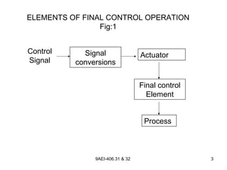
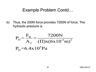
Instrumentation and process control fundamentalshossam hassanein
Basic course covers:
-Basic understanding of process control
-Important process control terminology
-Major components of a process loop
-Instrumentation P&ID symbols
Chapter 1 basic components of control systemHarish Odedra
This presentation is on basic of control engineering subject which is offered to 5th sem Mechanical Engineering Department in Gujarat Technological University.
Process load,process lag,self regulation,error,control lag,dead time,cycling,discontinious control modes,two position control modes,flaoting control modes,propotional band,offset,propotional control, integral control,derivative control,pid control,pi control,pd control,tuning of pid control
This Course basics of instrumentation and control systems used in oil and gas and petrochemical industry,
The course the following topics
Basics of Instrumentation
Field Instruments
Control Valves
Process Control
Control systems
CONTENTS
Measurements
Significance of Measurement system
Fundamental methods of Measurement
The generalized measurement system
Definitions & basic concepts
Errors in Measurements
Sources of errors
Accuracy Precision
Resolution
Linearity
Hysteresis
Impedance loading
Introduction to Transducers
Classification of transducers
Capacitive
Inductive
Resistive
Electromagnetic
Piezoelectric
Photoconductive
Photovoltaic
Pneumatic control valve
Actual Pneumatic Control Valve
Typical Actuator & Valve
introduction to actuator
Actuator power
Actuator Fluids
Diaphragm Actuator
Positioner Indicator
Valve Body
Valve Plugs
Reverse & Direct Actuators
Air-To-Open vs. Air-To-Close
control valve
Controller Tuning
Selection of controller modes
Tuning Rules
Ziegler – Nichols Controller Settings
CONTROL VALVE SIZING AND SELECTION FOR ANY APPLICATION.pptNagalingeswaranR
CONTROL VALVE BASICS.INCLUDING SIZIND, DETAILING AND SELECTION OF MATERIAL.THIS IS APPLICABLE FOR ALL APPLICATIONS LIKE UTILITY, POWER, WATER AND REFINERY. FROM THE PRESENTATION THE DESIGN ENGINEER CAN DECIDE THE TYPE OF CONTROL VALVE AND ITS CHARACTER TO BE SELECTED FOR THE GIVEN APPLICATION.
Energy Savings with Variable Frequency DrivesAzizah Kassim
To understand what is VFD / VSD / ASD / Inverter and what does it do.
To understand what is System Curve, Pump & Fan Curve and also Affinity Law
To understand how VFD saves AC motor ‘s energy
To estimate energy savings by using VFD to control speed of motor driving pumps / fans
To demonstrate few VFD’s applications in building and how it can save the energy
Fuzzy Logic Controller Based High Frequency Link AC-AC Converter For Voltage ...IJTET Journal
Abstract—In this paper, an advanced high frequency link AC-AC Push-pull cycloconverter for the voltage compensation is proposed in order to maintain the power quality in electric grid. The proposed methodology can be achieve arbitrary output voltage without using large energy storage elements. So that the system is more steadfast and less costly compared with the conventional inverter topology. Additionally, the proposed converter does not contain any line frequency transformer, which reduces the cost further. The control scheme for the push pull cycloconverter employs the fuzzy logic controller based sinusoidal pulse width modulation (SPWM) to accomplish better performance on voltage compensation, like unbalanced voltage harmonics elimination. The simulation results are given to show the effectiveness of the proposed high frequency link AC-AC converter and fuzzy logic controller based SPWM technology
Hybrid optimization of pumped hydro system and solar- Engr. Abdul-Azeez.pdffxintegritypublishin
Advancements in technology unveil a myriad of electrical and electronic breakthroughs geared towards efficiently harnessing limited resources to meet human energy demands. The optimization of hybrid solar PV panels and pumped hydro energy supply systems plays a pivotal role in utilizing natural resources effectively. This initiative not only benefits humanity but also fosters environmental sustainability. The study investigated the design optimization of these hybrid systems, focusing on understanding solar radiation patterns, identifying geographical influences on solar radiation, formulating a mathematical model for system optimization, and determining the optimal configuration of PV panels and pumped hydro storage. Through a comparative analysis approach and eight weeks of data collection, the study addressed key research questions related to solar radiation patterns and optimal system design. The findings highlighted regions with heightened solar radiation levels, showcasing substantial potential for power generation and emphasizing the system's efficiency. Optimizing system design significantly boosted power generation, promoted renewable energy utilization, and enhanced energy storage capacity. The study underscored the benefits of optimizing hybrid solar PV panels and pumped hydro energy supply systems for sustainable energy usage. Optimizing the design of solar PV panels and pumped hydro energy supply systems as examined across diverse climatic conditions in a developing country, not only enhances power generation but also improves the integration of renewable energy sources and boosts energy storage capacities, particularly beneficial for less economically prosperous regions. Additionally, the study provides valuable insights for advancing energy research in economically viable areas. Recommendations included conducting site-specific assessments, utilizing advanced modeling tools, implementing regular maintenance protocols, and enhancing communication among system components.
Saudi Arabia stands as a titan in the global energy landscape, renowned for its abundant oil and gas resources. It's the largest exporter of petroleum and holds some of the world's most significant reserves. Let's delve into the top 10 oil and gas projects shaping Saudi Arabia's energy future in 2024.
Overview of the fundamental roles in Hydropower generation and the components involved in wider Electrical Engineering.
This paper presents the design and construction of hydroelectric dams from the hydrologist’s survey of the valley before construction, all aspects and involved disciplines, fluid dynamics, structural engineering, generation and mains frequency regulation to the very transmission of power through the network in the United Kingdom.
Author: Robbie Edward Sayers
Collaborators and co editors: Charlie Sims and Connor Healey.
(C) 2024 Robbie E. Sayers
CFD Simulation of By-pass Flow in a HRSG module by R&R Consult.pptxR&R Consult
CFD analysis is incredibly effective at solving mysteries and improving the performance of complex systems!
Here's a great example: At a large natural gas-fired power plant, where they use waste heat to generate steam and energy, they were puzzled that their boiler wasn't producing as much steam as expected.
R&R and Tetra Engineering Group Inc. were asked to solve the issue with reduced steam production.
An inspection had shown that a significant amount of hot flue gas was bypassing the boiler tubes, where the heat was supposed to be transferred.
R&R Consult conducted a CFD analysis, which revealed that 6.3% of the flue gas was bypassing the boiler tubes without transferring heat. The analysis also showed that the flue gas was instead being directed along the sides of the boiler and between the modules that were supposed to capture the heat. This was the cause of the reduced performance.
Based on our results, Tetra Engineering installed covering plates to reduce the bypass flow. This improved the boiler's performance and increased electricity production.
It is always satisfying when we can help solve complex challenges like this. Do your systems also need a check-up or optimization? Give us a call!
Work done in cooperation with James Malloy and David Moelling from Tetra Engineering.
More examples of our work https://www.r-r-consult.dk/en/cases-en/
NO1 Uk best vashikaran specialist in delhi vashikaran baba near me online vas...Amil Baba Dawood bangali
Contact with Dawood Bhai Just call on +92322-6382012 and we'll help you. We'll solve all your problems within 12 to 24 hours and with 101% guarantee and with astrology systematic. If you want to take any personal or professional advice then also you can call us on +92322-6382012 , ONLINE LOVE PROBLEM & Other all types of Daily Life Problem's.Then CALL or WHATSAPP us on +92322-6382012 and Get all these problems solutions here by Amil Baba DAWOOD BANGALI
#vashikaranspecialist #astrologer #palmistry #amliyaat #taweez #manpasandshadi #horoscope #spiritual #lovelife #lovespell #marriagespell#aamilbabainpakistan #amilbabainkarachi #powerfullblackmagicspell #kalajadumantarspecialist #realamilbaba #AmilbabainPakistan #astrologerincanada #astrologerindubai #lovespellsmaster #kalajaduspecialist #lovespellsthatwork #aamilbabainlahore#blackmagicformarriage #aamilbaba #kalajadu #kalailam #taweez #wazifaexpert #jadumantar #vashikaranspecialist #astrologer #palmistry #amliyaat #taweez #manpasandshadi #horoscope #spiritual #lovelife #lovespell #marriagespell#aamilbabainpakistan #amilbabainkarachi #powerfullblackmagicspell #kalajadumantarspecialist #realamilbaba #AmilbabainPakistan #astrologerincanada #astrologerindubai #lovespellsmaster #kalajaduspecialist #lovespellsthatwork #aamilbabainlahore #blackmagicforlove #blackmagicformarriage #aamilbaba #kalajadu #kalailam #taweez #wazifaexpert #jadumantar #vashikaranspecialist #astrologer #palmistry #amliyaat #taweez #manpasandshadi #horoscope #spiritual #lovelife #lovespell #marriagespell#aamilbabainpakistan #amilbabainkarachi #powerfullblackmagicspell #kalajadumantarspecialist #realamilbaba #AmilbabainPakistan #astrologerincanada #astrologerindubai #lovespellsmaster #kalajaduspecialist #lovespellsthatwork #aamilbabainlahore #Amilbabainuk #amilbabainspain #amilbabaindubai #Amilbabainnorway #amilbabainkrachi #amilbabainlahore #amilbabaingujranwalan #amilbabainislamabad
About
Indigenized remote control interface card suitable for MAFI system CCR equipment. Compatible for IDM8000 CCR. Backplane mounted serial and TCP/Ethernet communication module for CCR remote access. IDM 8000 CCR remote control on serial and TCP protocol.
• Remote control: Parallel or serial interface.
• Compatible with MAFI CCR system.
• Compatible with IDM8000 CCR.
• Compatible with Backplane mount serial communication.
• Compatible with commercial and Defence aviation CCR system.
• Remote control system for accessing CCR and allied system over serial or TCP.
• Indigenized local Support/presence in India.
• Easy in configuration using DIP switches.
Technical Specifications
Indigenized remote control interface card suitable for MAFI system CCR equipment. Compatible for IDM8000 CCR. Backplane mounted serial and TCP/Ethernet communication module for CCR remote access. IDM 8000 CCR remote control on serial and TCP protocol.
Key Features
Indigenized remote control interface card suitable for MAFI system CCR equipment. Compatible for IDM8000 CCR. Backplane mounted serial and TCP/Ethernet communication module for CCR remote access. IDM 8000 CCR remote control on serial and TCP protocol.
• Remote control: Parallel or serial interface
• Compatible with MAFI CCR system
• Copatiable with IDM8000 CCR
• Compatible with Backplane mount serial communication.
• Compatible with commercial and Defence aviation CCR system.
• Remote control system for accessing CCR and allied system over serial or TCP.
• Indigenized local Support/presence in India.
Application
• Remote control: Parallel or serial interface.
• Compatible with MAFI CCR system.
• Compatible with IDM8000 CCR.
• Compatible with Backplane mount serial communication.
• Compatible with commercial and Defence aviation CCR system.
• Remote control system for accessing CCR and allied system over serial or TCP.
• Indigenized local Support/presence in India.
• Easy in configuration using DIP switches.
Immunizing Image Classifiers Against Localized Adversary Attacksgerogepatton
This paper addresses the vulnerability of deep learning models, particularly convolutional neural networks
(CNN)s, to adversarial attacks and presents a proactive training technique designed to counter them. We
introduce a novel volumization algorithm, which transforms 2D images into 3D volumetric representations.
When combined with 3D convolution and deep curriculum learning optimization (CLO), itsignificantly improves
the immunity of models against localized universal attacks by up to 40%. We evaluate our proposed approach
using contemporary CNN architectures and the modified Canadian Institute for Advanced Research (CIFAR-10
and CIFAR-100) and ImageNet Large Scale Visual Recognition Challenge (ILSVRC12) datasets, showcasing
accuracy improvements over previous techniques. The results indicate that the combination of the volumetric
input and curriculum learning holds significant promise for mitigating adversarial attacks without necessitating
adversary training.
Governing Equations for Fundamental Aerodynamics_Anderson2010.pdf
Process control 3 chapter
1. 9AEI-406.31 & 32 1
Final Control Element
Basic Principle of Final Control Element
• Final control element operations involve the steps
necessary to convert the control signal, (generated by
a process controller) into proportional action on the
process itself.
2. 9AEI-406.31 & 32 2
Final Control Element
• The process controller O/P signals are usually in one
of three forms.
• Electrical signal ( 4 -20 mA )
• Pneumatic signal (3 to 15 PSI)
• Digital signals usually TTL level voltages.
• By using the above signals the final control element
control the process.
3. 9AEI-406.31 & 32 3
ELEMENTS OF FINAL CONTROL OPERATION
Fig:1
Control
Signal
Signal
conversions
Actuator
Final control
Element
Process
4. 9AEI-406.31 & 32 4
Elements of a Final Control Operation
• Process-control application the conversion of a
process-controller signal to a control function can be
represented by the elements of a final control
operation as shown in fig 1.
5. 9AEI-406.31 & 32 5
Description of each block
1. Control Signal:
The input control signal may take many forms such as
• An electric current
• Pneumatic pressure
• Digital signal etc.,
6. 9AEI-406.31 & 32 6
Description…..
2. Signal conversions :
• This block refers to the modifications that must
be made to the control signal to properly
interface with the next stage of control, that is
actuator.
• Thus, if a valve control element is to be
operated by an electric motor actuator,
• Then a 4 - 20 mA DC control signal must be
modified to operate the motor
7. 9AEI-406.31 & 32 7
Description…..cont..
• If DC motor is used, modification might be current to
voltage conversion and amplification
• Signal conversions are often called transducers
because they convert control signals from one form to
other, such as
• Current to pressure
• Current to voltage
• Analog to digital
8. 9AEI-406.31 & 32 8
Description….
3. Actuators:
• The actuator is a translation of the converted control
signal into action on the control element.
• Thus, if a valve is to operated then the actuator is a
device that converts the control signal into physical
action of opening or closing the valve
9. 9AEI-406.31 & 32 9
Description….
4. Final control element:
• This device has direct influence on the process
dynamic variable and is designed as an integral part of
the process.
• Thus, if flow is to be controlled, then the control
element, a valve, must be built, directly into the flow
system.
• If temperature is to be controlled, then some control
element that has a direct influence on temperature
must be involved in the process.
10. 9AEI-406.31 & 32 10
Description….
4. Final control element:
• This could be a heater / cooler combination, that is
electrically actuated by relays or a pneumatic valve to
control influx of reactants.
11. 9AEI-406.31 & 32 11
Applications of final control element
• To regulate the flow rate in a fluid delivery system.
• To control the degree of backing of crackers in cracking
systems etc.,
• To maintain level, temperature etc., in process industries.
12. 12 9AEI-406.33
Need for E/P and P/E converter
• Signal conversions are often called transducers because
they convert control signals from one form to other, such
as
• Electrical to pressure (E/P)
• Pressure to electrical (P/E)
• The electrical signal in the form of current signal.
13. 13 9AEI-406.33
Need for Current-to-Pressure converter
The P/I converter is used wherever pneumatic signals
must be converted to electronic signals for any one of
the following reasons.
• Transmission over large distances.
• Input to an electronic data logger or computer.
• Input to Telemeter equipment.
• Instrument air not available at the receiver controller.
14. 14 9AEI-406.33
Need for Current-to-Pressure converter
• When we want to use the low level electric current signal
to do work, it is much easier to let the work to be done by
a pneumatic signal.
15. 15 9AEI-406.33
Pressure-to-Current converter
• The pressure-to-current converter, or simply P/I
converter, is complementary to I/P converter.
• In principle, any of the electronics pressure transmitters
could be used, but in practice, special devices are used
to improve accuracy.
17. 17 9AEI-406.33
• Because of this need for accuracy, most P/I converters
use a bellows input and a motion balance sensor.
• A typical high quality P/E converter is shown in Fig. 4.8.
The voltage output can be converted into current values
with number of standard circuits.
18. 18 9AEI-406.33
• Bellow is convert the pneumatic control signal (3-15 psi)
in to displacement signal.
• Bellow elongation sensed by LVDT (Linear Variable
Differential Transformer.
19. 19 9AEI-406.33
• The air signals are at low pressure levels (0.2 to 1
Kg/cm2, or 3 psi to 15 psi), and many of the pressure
detectors are not sensitive or not linear enough at these
pressures.
• A P/I converter should be at least 0.5% accurate and
preferably 0.25% to preserve the integrity of the initial
signal.
21. 21 9AEI-406.34
• The current-to-pressure converter, or simply I/P
converter, is a very important element in process control.
• The I/P converter gives us a linear way of translating the
4-20 m A current into a 0.2 to 1 Kg/cm2
signal (3 to 15 psi
signal).
22. 22 9AEI-406.34
Current-to-Pressure converter
• There are many designs for these converters, but the
basic principle almost always involves the use of a
flapper/nozzle system.
• Fig. 1 illustrates a simple way to construct such a
converter.
24. 24 9AEI-406.34
• The current through a coil produces a force that will tend
to pull the flapper down and close off the gap.
• A high current produces a high pressure so that the
device is direct acting.
25. 25 9AEI-406.34
• Adjustment of the springs and perhaps the position
relative to the pivot to which they are attached allows
the unit to be calibrated so that 4 mA corresponds to 0.2
Kg/cm2 ( or 3 psi) and 20 mA corresponds to 1 kg/cm2
(or 15 psi).
• Fig. 2 illustrates the construction of one such converters
and also lists the various electric devices with which it is
commonly combined.
27. 27 9AEI-406.34
• A permanent magnet creates a field that passes through
the steel body of the transmitter and across a small air
gap to the pole piece.
• A multi turn, flexure-mounted voice coil is suspended in
the air gap.
• The input current flows through the coil creating an
electromagnetic force that tend to repel the coil and thus
converts the current signal into a mechanical force.
28. 28 9AEI-406.34
• Since the total force obtainable in a typical voice coil
motor with small current inputs is very less, a different
approach, namely, the use of a reaction nozzle, is
employed here to convert the force into a pneumatic
output pressure.
29. 29 9AEI-406.34
• In this circuit, supply air flows through a restriction and
out the detector nozzle.
• The reaction of the air jet as it impinges against the
nozzle seat supplies the counterbalancing force to the
voice coil motor.
30. 30 9AEI-406.34
• The nozzle back pressure is the transmitted output
pressure.
• In order to make the transmitter insensitive to vibration,
the voice coil is integrally mounted to a float submerged
in silicone oil.
• The float is sized so that its buoyant force equals the
weight of the assembly, leaving a zero net force.
31. 31 9AEI-406.34
• Zero is adjusted by changing a leaf spring force.
• Span is adjusted by turning the range adjusting screw to
change the gap between the screw and the magnet thus
shunting some of the magnetic fielded away from the pole
piece.
• Such converter are called motion balance type converter.
• A force balanced type converter with signal feedback to
improve accuracy is shown in fig.3.
33. 9AEI-406.35 33
Actuators
• Actuators converts the control signal into action on the
control elements
Eg:
if a valve is to be operated then the actuator is a device
that converts the control signal into physical action of
opening or closing the valve
34. 9AEI-406.35 34
Actuators…..
• The actuator must provide an accurate output position
proportional to the input signal in spite of various forces
acting on the output member.
• They often translates a control signals into a large force
or torque as required to manipulate some control
element
35. 9AEI-406.35 35
Classification of actuators
Actuators are classified as
• Pneumatic actuators
• Hydraulic actuators
• Electro pneumatic actuators
• Electric motor actuator
36. 9AEI-406.35 36
• Pneumatic actuators may operate directly from the
pneumatic output signal from a pneumatic controller or
they may employ a separate source of compressed air.
• The principle is based on the concept of pressure as
force per unit area.
• It net pressure difference (P2 – P1) is applied to a
diaphragm of surface area A; the net force (F) acting on
it is given as F = (P2 – P1) A.
Pneumatic actuator
39. 9AEI-406.35 39
• Fig. 1 shows the condition in the low signal pressure
state.
• It consists of spring, control shaft and diaphragm.
• The pressure on the opposite side of the diaphragm is
maintained at atmospheric pressure by the open hole H.
• The input pressure applies a force on the diaphragm
40. 9AEI-406.35 40
• It forces the diaphragm and connects the shaft to down
side against the spring force.
• The figure 2 shows the maximum control pressure and
maximum travel of shaft.
• The pressure and force are linearly related.
41. 9AEI-406.35 41
• The shaft position is linearly related to the applied control
pressure
Where
= shaft travel (m)
= applied gauge pressure (Pascals)
A = diaphragm area(m2
)
K = spring constant (N/m2
)
p∆
A
x p
k
∆ = ∆
x∆
44. 44 9AEI-406.36
Electro Pneumatic Actuators
• When an electric control systems are employed, it is
often advantageous to use a pneumatic actuator.
• If a suitable air supply is available, a pneumatic actuator
can provide very large power output and may be
operated directly from an electric control system.
• This requires transducing the electrical output of the
controller into an input variable for the actuator.
45. 45 9AEI-406.36
Electric Pneumatic Actuators
• The electro pneumatic pilot is shown in fig (1). It converts
an electrical signal input to a proportional air pressure
output.
• The input electric signal is usually a direct current.
• “Voice coil” motor accepts direct current as input signal.
47. 47 9AEI-406.36
Electro Pneumatic Actuators
• The “Voice Coil” motor converts the direct current into a
mechanical force when placed in a magnetic field.
• The force causes a deflection of the balance beam,
covers the nozzle and results in an increase of output
pressure.
48. 48 9AEI-406.36
Electro Pneumatic Actuators
• The output pressure acts on the feedback bellows to
cause a torque on the balance beam equal but
opposite to that of the voice coil.
• The output pressure therefore is proportional to the
input dc current.
• The electro - pneumatic actuator is shown in fig 2.
50. 50 9AEI-406.36
• The motion of the output of the actuator is related to the
balance beam through the feedback lever.
• The output position of the actuator is therefore proportional
to input direct current.
51. 51 9AEI-406.36
Advantages
• Low cost
• Simple design
• Mechanical fail safe
• Suitable for high hazardous area
• Good control with control device
53. 53 9AEI-406.37
Hydraulic Actuator
• Hydraulic actuator accepts a signal from a pneumatic
controller or an electric controller and employ hydraulic
pressure to drive an output member.
• The hydraulic actuator is used where high speed and
large forces are required.
• The basic principle is shown in figure 3
54. 54 9AEI-406.37
Hydraulic Actuator
• The basic idea is the same as for pneumatic actuators
except that an incompressible fluid is used to provide
the pressure.
• The hydraulic pressure can be made very large by
adjustments of the area of the forcing piston A1.
56. 56 9AEI-406.37
• The hydraulic pressure is given by
PH = F1 / A1
• Where PH = hydraulic pressure (Pa)
F1 = applied piston force (N)
A1 = forcing piston area (m2
)
57. 579AEI-406.37
• The resulting force on the working piston is
FW = PHA2
Where FW = force of working piston (N)
A2 = working piston area (m2
)
• Thus, the working force is given in terms of the applied
force by
2
1
W
1
A F
F
A
=
59. 59 9AEI-406.37
1. Find the working force resulting from 200N applied to a
1cm radius forcing piston
a) If the working piston has a radius of 6cm. Then
b) Find the hydraulic pressure
Example Problem
60. 609AEI-406.37
Solution :
a) We can find the working force from,
2 2
2
1
1
6
. .(200 )
1
w
R Cm
F F N
R Cm
= = ÷ ÷
FW = 7200N
Example Problem Contd…
2
1
W
1
A F
F
A
=
61. 61 9AEI-406.37
b) Thus, the 200N force provides 7200N of force. The
hydraulic pressure is
W
H -2 2
2
5
H
F 7200N
P = =
A (Π)x(6x10 m)
P =6.4x10 Pa
Example Problem Contd…
65. 9AEI-406.38 65
Solenoid
• A solenoid is an elementary device that converts an
electrical signal into mechanical motion, usually in a
straight line.
68. 9AEI-406.38 68
• A simple solenoid consists of a coil and plunger as
shown in Fig. 1.
• The plunger may be free standing or spring loaded.
• The coil may be operated by either dc or ac voltage.
69. 9AEI-406.38 69
Specifications
• Solenoid specifications include the electrical rating and
the plunger pull or push force when excited by the
specified voltage.
• Some solenoids are rated only for intermittent duty
because of thermal constraints.
• In this case, the maximum duty cycle ( percentage on
total time) will be specified.
70. 9AEI-406.38 70
Applications
• Solenoids are used when a large sudden force must be
applied to perform some job.
• These actuators are best suited for small, short-stroke
on-off valves, requiring high speeds of response.
• Solenoid-actuated valves can open or close in 8 to 12
milliseconds.
71. 9AEI-406.38 71
• In Fig. 2 a solenoid is used to change the gears of a two-
position transmission.
• An SCR is used to activate the solenoid coil.
73. 9AEI-406.38 73
• In many process control pipe lines solenoid values
(where the plunger can act as value stem also) are used
for quick closing or shut-off operations.
• In large pipelines shut-off values are operated with the
help of pneumatic air or hydraulic oil which are in turn
controlled by solenoids valves fitted in the air line or oil
line.
74. 9AEI-406.38 74
• Solenoids move in a straight line and therefore require a
cam or other mechanical converter to operate rotary
values.
75. 9AEI-406.38 75
• A practical solenoid valve consists of the valve body, a
magnetic core attached to the stem and disc, and a
solenoid coil (Refer Fig. 4.11).
• The magnetic core moves in a tube that is closed at the
top and sealed at the bottom, allowing the valve to be
packless.
77. 9AEI-406.38 77
• A small spring assists the release and initial closing of
the valve. The valve is electrically energized to open.
• The figure shows both the reenergized and energized
conditions of the valve for better understanding.
78. 9AEI-406.38 78
Disadvantages
• Although the force output of solenoids may not have
many electrical or mechanical limitations, their use as
valve actuators has economic and core (or stem) travel
limitations, and they are expensive too.
79. 9AEI-406.38 79
• Designs are available with a separate positioned which
accepts 4-20 mA from controller and delivers a dc
output signal to the solenoid.
• Valve position feedback is obtained through the use of a
linear variable differential transformer (LVDT) mounted
directly on the valve.
81. 9AEI-406.39 81
Stepper Motor
• A stepping motor is a rotating machine that actually
completes a full rotation by sequencing through a series
of discrete rotational seeps.
• Each step position is an equilibrium position in that,
without further excitation, the rotor position will stay at
the latest step.
82. 9AEI-406.39 82
Stepper Motor
• Thus, continuous rotation is achieved by the input of a
train of pulses, each of which causes an advance of one
step.
• It is not really Continuous rotation, but discrete, stepwise
rotation.
• The rotational rate is determined by the number of steps
per revolution and the rates at which the pulses are
applied.
85. 9AEI-406.39 85
• The operation of a stepping motor can be understood
from the simple model shown in Figure1,
• Which has 90 per step.
• In this motor, the rotor is a PM that is driven by a
particular set of electromagnets.
• In the position shown, the system is in equilibrium and
no motion occurs.
86. 9AEI-406.39 86
• The switches are typically solid-state devices, such as
transistors, SCRs, or TRICACs.
• The switch sequencer will direct the switches through a
sequence of positions as the pulses are received.
• The next pulse in Figure 2a will change S2 from C to D,
resulting in the poles of that electromagnet reversing
fields.
88. 9AEI-406.39 88
• Now, because the pole north/south orientation is
different, the rotor is repelled and attracted so that it
moves to the new position of equilibrium shown in Figure
2b.
• With the next pulse, S1 is changed to B, causing the
same kind of pole reversal and rotation of the PM to a
new position, as shown in Figure 2c.
89. 9AEI-406.39 89
• Finally, the next pulse cause S2 to switch to C again, and
the PM rotor again steps to a new equilibrium position,
as in Figure 2d.
• The next pulse will send the system back to the original
state and the rotor to the original position.
• This sequence is them repeated as the pulse train
comes in, resulting in a stepwise continuous rotation of
the rotor PM.
90. 9AEI-406.39 90
• The most common stepper motor does not use a PM,
but rather a rotor of magnetic material (not a magnet)
with a certain number of teeth.
• This rotor is driven by a phased arrangement of coils
with a different number of poles so that the rotor can
never be in perfect alignment with the stator.
92. 9AEI-406.39 92
• Figure 7.26 illustrates this for a rotor with 8 “teeth” and a
stator with 12 “poles.”
• One set of four teeth is aligned, but the other four are
not. If excitation is placed on the next set of poles (B)
and taken off the first set (A), then the rotor will step
once to come into alignment with the B set of poles.
• The direction of rotation of stepper motors can be
changed just by changing the order in which different
poles are activated and deactivated.
94. 9AEI-406.40 & 41 94
Control Valve
• A valve is a device that regulates the flow of a fluid
(gases, liquids, fluidized solids, or slurries) by opening,
closing, or partially obstructing various passageways.
• Valves are technically pipe fittings,. In an open valve,
fluid flows in a direction from higher pressure to lower
pressure.
96. 9AEI-406.40 & 41 96
• Control valves are valves used to control conditions
such as flow, pressure, temperature, and liquid level by
fully or partially opening or closing in response to signals
received from controllers that compare a "set point" to a
"process variable" whose value is provided by sensors
that monitor changes in such conditions.
97. 9AEI-406.40 & 41 97
• The opening or closing of control valves is done by
means of electrical, hydraulic or pneumatic systems.
• Petitioners are used to control the opening or closing of
the actuator based on Electric, or Pneumatic Signals.
• These control signals, traditionally based on 3-15psi
(0.2-1.0bar), more common now are 4-20mA signals for
industry, 0-10V for HVAC systems.
98. 9AEI-406.40 & 41 98
Construction of control valve
• The control valve is basically divided into three main
parts
• Valve body and Bonnet
• Stem
• plug
99. 9AEI-406.40 & 41 99
1) Body 2) Head 3) Ball 4) Lever handle
5) Stem
100. 9AEI-406.40 & 41 100
Body and bonnet
• The main parts of a valve are the body and the bonnet.
• These two parts form the casing that holds the fluid
going through the valve.
• The bonnet is the casing through which the stem (see
below) passes and that forms a guide and seal for the
stem.
101. 9AEI-406.40 & 41 101
• Valve bodies are usually metallic. Brass, bronze,
gunmetal, cast iron, steel, alloy steels and stainless
steels.
• Seawater applications, like desalination plants, often use
duplex valves, as well as super duplex valves, due to
their corrosion resistant properties, particularly against
warm seawater.
102. 9AEI-406.40 & 41 102
Body materials for various applications
• Alloy 20 valves are typically used in sulphuric acid
plants,
• Monel valves are used in hydrofluoric acid (HF Acid)
plants.
• Hastelloy valves are often used in high temperature
applications, such as nuclear plants,
• Inconel valves are often used in hydrogen applications.
• Plastic bodies are used for relatively low pressures and
temperatures. PVC, PP (Polypropylene), PVDF
(Polyvinylidene fluoride) and glass-reinforced nylon are
common plastics used for valve bodies.
103. 9AEI-406.40 & 41 103
Bonnet
• A bonnet acts as a cover on the valve body.
• It is commonly semi-permanently screwed into the valve
body.
• During manufacture of the valve, the internal parts are
put into the body and then the bonnet is attached to hold
everything together inside.
104. 9AEI-406.40 & 41 104
Ports
• Ports are passages that allow fluid to pass through the
valve.
• Ports are obstructed by the valve member or disc to
control flow.
• Valves most commonly have 2 ports, but may have as
many as 20.
• The valve is almost always connected at it's ports to
pipes or other components.
• Connection methods include threadings, compression
fittings, glue, cement, flanges, or welding
105. 9AEI-406.40 & 41 105
Disc
• A disc or valve member is a movable obstruction inside
the stationary body that adjustably restricts flow through
the valve.
• Although traditionally disc-shaped, discs come in various
shapes.
• A ball is a round valve member with one or more paths
between ports passing through it.
106. 9AEI-406.40 & 41 106
• By rotating the ball flow can be directed between
different ports.
• Ball valves use spherical rotors with a cylindrical hole
drilled as a fluid passage.
• Plug valves use cylindrical or conically tapered rotors
called plugs.
107. 9AEI-406.40 & 41 107
Seat
• The seat is the interior surface of the body which
contacts the disc to form a leak-tight seal.
• In discs that move linearly or swing on a hinge the disc
comes into contact with the seat only when the valve is
shut.
• In disks that rotate, the seat is always in contact with the
disk, but the area of contact changes as the disc is
turned. The seat always remains stationary relative to
the body.
• Seats are classified by whether they are cut directly into
the body, or if they are made of a different material:
108. 9AEI-406.40 & 41 108
• Hard seats are integral to the valve body. Nearly all hard
seated metal valves have a small amount of leakage.
• Examples: Gate, globe, and check valves are usually
hard seated.
• Soft seats are fitted to the valve body and made of
softer materials such as PTFE (Poly tetrafluoroethylene)
or various elastomers such as NBR (Nitrile butadiene
rubber) , EPDM (ethylene propylene diene Monomer (M-class)
rubber), or FKM (Fakultas Kesehatan Masyarakat) depending
on the maximum operating temperature.
• Examples: butterfly, ball, plug, and diaphragm valves are
usually soft seated.
109. 9AEI-406.40 & 41 109109
• Stem is nothing but a vertical metallic shaft or rod.
• The stem transmits motion from controlling device to the
disc.
• The stem typically passes through the bonnet when present.
• The motion transmitted by the stem may be a linear force, a
rotational torque, or some combination of these.
Stem
110. 9AEI-406.40 & 41 110
Gaskets
• The seals or packings used to prevent the escape of a
gas or fluids from valves.
112. 9AEI-406.40 & 41 112
• The valve plug is screwed into stem and then pinned
• It can be a single seated plug or double seated plug
which is guided at the top and bottom
Plug
113. 9AEI-406.40 & 41 113
• According to their basic shapes, plugs can be classified
as
• Disc
• V – shape
• Contoured
Construction of control valve (contd..)
117. 9AEI-406.42 117
Types of control valves
• There are three basic types of control valves whose
relationship between stem position and flow rate
• These are :
• Quick opening control valve
• Linear control valve
• Equal percentage control valve
120. 9AEI-406.42 120
Control Valve Flow Characteristics
• The most common characteristics are shown in the
figure above.
• The percent of flow through the valve is plotted against
valve stem position.
• The curves shown are typical of those available from
valve manufacturers.
• These curves are based on constant pressure drop
across the valve and are called inherent flow
characteristics.
123. 9AEI-406.42 123
Control Valve Flow Characteristics
• Linear - flow capacity increases linearly with valve travel.
• Equal percentage - flow capacity increases
exponentially with valve trim travel. Equal increments of
valve travel produce equal percentage changes in the
existing Cv.
• A modified parabolic characteristic is approximately
midway between linear and equal-percentage
characteristics. It provides fine throttling at low flow
capacity and approximately linear characteristics at
higher flow capacity.
124. 9AEI-406.42 124
• Quick opening provides large changes in flow for very
small changes in lift. It usually has too high a valve gain
for use in modulating control. So it is limited to on-off
service, such as sequential operation in either batch or
semi-continuous processes.
• Hyperbolic
• Square Root
• The majority of control applications are valves with
linear, equal-percentage, or modified-flow characteristics
125. 9AEI-406.42 125
Quick Opening Control Valve
• This type of valve is used predominantly for full on /
full off control applications
• A relatively small motion of valve, for example ,
may allow 90% of maximum flow rate with only a
30% travel of the stem
126. 9AEI-406.42 126
Linear valve
• This type of valve has a flow rate that varies linearly with
the stem position
• It represents the ideal situation where the valve alone
determines the pressure drop
127. 9AEI-406.42 127
Linear valve
• The relationship is expressed as
max max
Q S
=
Q S
Where
Q = flow rate (m3
/s)
Qmax = maximum flow rate (m3
/s)
S = stem position (m)
Smax = maximum stem position (m)
128. 9AEI-406.42 128
Equal percentage valve
• This is a very important type of valve employed in flow
control
• It has a characteristics such that a given percentage
change in stem position produces an equivalent change
in flow , i.e. an equal percentage
129. 9AEI-406.42 129
• Generally, this type of valve does not shut-off the
flow completely in its limits of stem travel
• At the other extreme, the valve allows a maximum
flow Qmax.
Equal percentage valve (contd..)
130. 9AEI-406.42 130
• For this type we define rangeability R as the ratio
R = Qmax/ Qmin
• The curve in fig. 1 shows that increase in flow rate for a
given change in valve opening depends the extent to
which the valve is already open
• This curve typically exponential in form and is
represented by
Q = Qmin .RS/Smax
Equal percentage valve (contd..)
131. 9AEI-406.43 & 44 131
Different Types Of Control Valves
• Globe control valve:
• Sliding Stem Control Valves:
• Lifting Gate Valves
• Rotating-Shaft Control Valves
132. 9AEI-406.43 & 44 132
Sliding Stem Control Valves:
• Control valves in which the plug is operated by means
of reciprocating motion are termed sliding stem valves
and are of following types
1.Single seat plug valves
2.Double seat plug valves.
3.Lifting-gate valves.
134. 9AEI-406.43 & 44 134
Single Seat Control Valve
Fig:2, a single seat control valve and pneumatic actuator
135. 9AEI-406.43 & 44 135
Single Seat Control Valve
• Figure 2 is a diagrammatic representation of a single
seat two-port globe valve.
• In this case the fluid flow is pushing against the valve
plug and tending to keep the plug off the valve seat.
136. 9AEI-406.43 & 44 136
Single Seat Control Valve
• The vertical movement of the plug and stem of the
control valve changes the area of opening of the port.
• The flow rate of the fluid passing through the port is
therefore proportioned or throttled by positioning the
valve stem. The stem in turn positioned by the
actuator.
138. 9AEI-406.43 & 44 138
A few types of single seat valve plugs
• The V-port type plug is open on the inside and the
flow passes horizontally through the triangular
shaped area over the seat ring as in the fig. 3.
139. 9AEI-406.43 & 44 139
Single Seat Plug Valves
• It has the following features:
a)It is simple in construction
b)It can be shut off to provide zero flow.
c)There is a large force acting on the valve stem
because of the differential head acting across the port
and seat area.
140. 9AEI-406.43 & 44 140
Need for Double seat valve
• If a larger valve, having a larger orifice, is used to pass
greater volumes of the medium, then the force that the
actuator must develop in order to close the valve will
also increase.
• Where very large capacities must be passed using large
valves, or where very high differential pressures exist,
the point will be reached where it becomes impractical to
provide sufficient force to close a conventional single
seat valve.
• In such circumstances, the traditional solution to this
problem is the double seat two-port valve.
142. 9AEI-406.43 & 44 142
Double Seat Plug Valve
• The double seat valve has two port openings and
two seats and two plugs.
• The port openings are not usually identical in size
as in fig.4
144. 9AEI-406.43 & 44 144
Double Seat Plug Valve
This type has the following features.
• Net force acting on the valve stem is generally
small therefore pressure balanced.
• It cannot be shut off tightly because of differential
temperature expansion of value plug and valve
body
145. 9AEI-406.43 & 44 145
Double Seat Plug Valve
• Few types of plugs for single seat and double seat
valves are shown in fig :5
• The piston type plug has one or more grooves along its
length and the flow passes vertically in the grooves
between the plug and seat ring.
146. 9AEI-406.45 146
GATE VALVES
• Gate valves are used when a straight-line flow of fluid
and minimum restric-tion is desired.
• Gate valves are so named because the part that either
stops or allows flow through the valve acts somewhat
like the opening or closing of a gate and is called,
appropriately, the gate.
• The gate is usually wedge shaped.
147. 9AEI-406.45 147
• When the valve is wide open, the gate is fully drawn up
into the valve, leaving an opening for flow through the
valve the same size as the pipe in which the valve is
installed.
• Therefore, there is little pressure drop or flow restriction
through the valve.
149. 9AEI-406.45 149
Disadvantages
• Gate valves are not suitable for throttling purposes since
the control of flow would be difficult due to valve design
and since the flow of fluid slapping against a partially
open gate can cause extensive damage to the valve.
150. 9AEI-406.45 150
Lifting Gate Valves
• Lifting gate valves are shown in figure .3
• The gate valve in fig.1 is often used for fluids containing
solid matter, because it presents an open area directly to
the flow of fluid and does not involve a change of
direction of flow stream.
• A gate valve can usually be shut off tightly by wedging
into the seat.
• The chopping action at shut off is very useful for stringy
materials such as paper pulp.
154. 9AEI-406.45 154
Weir Valve
• It is also called Diaphragm valves (or) membrane
valves
• The weir valve of fig.5 particularly suited to certain
chemical fluids, because it has a smooth contour inside
the body with no “pockets” for solid matter and because
it has no packing gland around the stem.
155. 9AEI-406.45 155
Weir Valve
• The flexible diaphragm of rubber or other non metallic
material is positioned by the plunger and stem.
• Fluid pressure inside the valve body holds the
diaphragm smoothly against the plunger.
158. 9AEI-406.45 158
Applications of Diaphragm Valve
• Diaphragm valves can be manual or automated.
• Their application is generally as shut-off valves in
process systems within the food and beverage,
pharmaceutical and biotech industries.
159. 9AEI-406.46 159
Rotating-Shaft Control Valves
• Control valves in which the restriction is accomplished
by the rotation of a plug or vane may be called
rotating-shaft type.
• Rotary type valves, often called quarter-turn valves,
• All require a rotary motion to open and close, and can
easily be fitted with actuators.
161. 9AEI-406.46 161
Eccentric plug valves
• Figure 1 shows a typical eccentric plug valve.
• These valves are normally installed with the plug spindle
horizontal as shown, and the attached actuator situated
alongside the valve.
• Plug valves may include linkages between the plug and
actuator.
163. 9AEI-406.46 163
Rotating Ball valves
• Figure 2 shows a ball valve consisting of a spherical ball
located between two sealing rings in a simple body form.
• The ball has a hole allowing fluid to pass through. When
aligned with the pipe ends, this gives either full bore or
nearly full bore flow with very little pressure drop.
• Rotating the ball through 90° opens and closes the flow
passage.
• Ball valves designed specifically for control purposes will
have characterized balls or seats, to give a predictable
flow pattern.
165. 9AEI-406.46 165
Advantages of ball valves
• Ball valves are an economic means of providing control
with tight shut-off for many fluids including steam at
temperatures up to 250°C (38 bar g, saturated steam).
• Above this temperature, special seat materials or metal-
to-metal seating are necessary, which can be expensive.
• Ball valves are easily actuated and often used for remote
isolation and control.
• For critical control applications, segmented balls and
balls with specially shaped holes are available to provide
different flow characteristics.
166. 9AEI-406.46166
Rotary Plug Valve
• The Rotating plug is shown in fig.3
• The plug is a cylindrical or conical element with a
transverse opening.
168. 9AEI-406.46 168
Rotary Plug Valve
• It is rotated in the valve body by an external lever so
that the opening on one side of the plug is gradually
covered or uncovered.
• The shape of the opening or port may be circular, V-
shape, rectangular, or any form that is desired to
produce a given flow-angle characteristic.
169. 9AEI-406.46 169
Rotary Plug Valve
• A rotating plug valve having a conical plug can generally
be closed tightly and has high range ability.
• This type of valve is often employed for throttling the flow
of oil to burner systems.
• The valve with a spherical plug that control the flow of
fluid through the valve body is called as ball valve.
170. 9AEI-406.47 to 48 170
Butterfly valves
• The valve is similar in operation to a ball valve.
• Rotating the handle turns the plate either parallel or
perpendicular to the flow of water, shutting off the flow.
172. 9AEI-406.47 to 48 172
Butterfly valves
• Schematic diagram of a butterfly valve, which consists of
a disc rotating in on bearings.
• In the open position the disc is parallel to the pipe wall,
allowing full flow through the valve.
• In the closed position it is rotated against a seat, and
perpendicular to the pipe wall.
173. 9AEI-406.47 to 48 173
• Traditionally, butterfly valves were limited to low
pressures and temperatures, due to the inherent
limitations of the soft seats used.
• Currently, valves with higher temperature seats or high
quality and specially machined metal-to-metal seats are
available to overcome these drawbacks.
• Standard butterfly valves are now used in simple control
applications.
• Particularly in larger sizes and where limited turndown is
required.
174. 9AEI-406.47 to 48 174
• A fluid flowing through a butterfly valve creates a low
pressure drop, in that the valve presents little resistance
to flow when open.
• In general however, their differential pressure limits are
lower than those for globe valves.
• Ball valves are similar except that, due to their different
sealing arrangements, they can operate against higher
differential pressures than equivalent butterfly valves.
177. 9AEI-406.47 to 48 177
• Butterfly valves are valves with a circular body and a
rotary motion disk closure member which is pivotally
supported by its stem.
• A butterfly valve can appear in various styles, including
eccentric and high-performance valves.
• These are normally a type of valve that uses a flat plate
to control the flow of water.
178. 9AEI-406.47 to 48 178
• As well as this, butterfly valves are used on firefighting
apparatus and typically are used on larger lines, such as
front and rear suction ports and tank to pump lines.
• A butterfly valve is also a type of flow control device,
used to make a fluid start or stop flowing through a
section of pipe.
179. 9AEI-406.47 to 48 179
Butterfly Valve
• The total rotation of the vane is usually restricted to
about 60 degrees, because the addition of 30 deg
does not produce much further increase in flow.
• The V-port butterfly valve incorporates a V-slot in the
body so that rotation of the vane opens a portion of
the V-slot.
• The range ability may vary from 5 to 50 and tight shut
off may be obtained with special design.
182. 9AEI-406.47 to 48 182
Application
• The butterfly valve is most often employed for the control
of air and gas
183. 9AEI-406.47 to 48 183
Louvers
• The louvers consists of two or more rectangular vane
mounted on shafts one above the other and is inter
connected so as to rotate together
• The vanes or operated by an external lever
• In the unirotational louver the vanes remain at all
position
• In a counter rotational louver alternate vanes rotate in
the opposite direction
185. 9AEI-406.47 to 48 185
Louvers
• Flow guide or some time installed between adjacent
vanes in order to improve the effective ness of throttling
• A louver can not provide a tight shut-off because of the
long length of seat surfaces
186. 9AEI-406.47 to 48 186
Application
• Louvers are used exclusively for control of air flow (draft)
at low pressure.