The document discusses proportional electrohydraulics. It describes how proportional valves regulate pressure or flow according to an electronic reference signal. Proportional valves are operated by electronic drivers that regulate electrical current to the valve's solenoid based on the reference signal. This current is converted into a mechanical force that moves the spool to control hydraulic output. Control loops can be open-loop or closed-loop depending on the required accuracy.
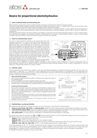
![6 TYPICAL DIAGRAMS OF PROPORTIONAL CONTROLS
Valve’s-regulated pressure variation
according to the reference signal
Valve’s-regulated pressure variation accor-
ding to the flow passing through the valve
6.1 PRESSURE CONTROL VALVES
Reference signal [% of max]
Regulatedpressure[%ofmax]
Flow rate [l/min]
Regulatedpressure[bar]
Regulated flow vs. functional Δp at max refe-
rence input signal
Pressure variation on use ports depending to
the spool stroke (only for valves with zero
overlapping in rest position).
Valve’s-regulated flow variation according to the
reference input signal
Pressure gain diagram
6.2 DIRECTIONAL AND FLOW CONTROL VALVES
Valve pressure drop ͬP [bar]
Flow[l/min]
Reference signal [% of max]
Maxflow[l/min]
ͬPA→B[%Pp]
The time lag required by the valve to reach
the requested hydraulic ragulation in front of
a step change in the reference input signal
(usually 0÷100%).
Response time is measured in millisecond
[ms] from 10 to 90 % of the step valve.
The curve shows for typical regulation ranges
(±5% and ± 90%) at different sinusoidal refe-
rence input signal frequency:
A) amplitude ratio variation, between reference
input signal and the regulated spool position
output signal;
B) phase lag between reference input signal and
the regulated spool position signal.
The maximum difference in the valve regula-
tion between reference input signal from 0 to
maximum and than from maximum to zero.
Hysteresis is measured in percentage of the
maximum value of the regulated hydraulic
parameter.
Response time Reference signal
Regulatedparameter
Frequency [Hz]
Amplituderatio[dB]
Regulatedparameter
Operating diagramRegulation diagram
Regulation diagram at characteristic ͬp Regulation diagram at max reference signal
Spool stroke [%]
Bode diagram HysteresisResponse time - step input
A1 A2
B1 B2
01/15
Phase[degree]
Repeatability: The maximum difference in the valve’s hydraulic regulation repeating the same input reference signal. Repeatability is measured
in percentage of the maximum value of the regulated hydraulic parameter.
Overlap: Percentage of spool stroke, starting from the central position, in which the valve remain closed.
Fail safe: spool’s safety hydraulic configuration in absence of electrical power supply
Linear spool: provides linear correspondence between valves regulation and reference input signal
Progressive spool: provides progressive regulation for finest low flow control
Differential spool: as progressive but with P-B = 50% of P-A
Leakage: The flow passing through port P to tank port T with the valve spool in central position. It is directly connected with the quality of the
valve’s mechanical execution.
Reference input signal: The electric signal sent from machine CNC to the valve electronic driver to obtain the required regulation value.
Driving current: The current sent from the electronic driver to the valve’s solenoid.
Bias current: Static offset added to the reference input signal required to compensate positive overlap spools.
Dither: The pulse frequency of the driver regulation used to minimize the valve hysteresis.
Regulation scale: Setting of the valve regulation with the max reference signal.
Ramp time: Time (in sec.) required to smoothly operate the valve in front of a step reference input signal.
5 TYPICAL ELECTROHYDRAULIC TERMS](https://image.slidesharecdn.com/f001-160804152018/85/F001-2-320.jpg)


![DESIGN AND FABRICATION OF THE IBM 90-90 SEAT BELT CLAMP KIA VEHICLE[1].pptx 2...](https://cdn.slidesharecdn.com/ss_thumbnails/designandfabricationoftheibm90-90seatbeltclampkiavehicle1-260116160442-70ff67fc-thumbnail.jpg?width=640&height=640&fit=bounds)


![[English Version]Maker-Ray Product Brochure V3 .pdf](https://cdn.slidesharecdn.com/ss_thumbnails/englishversionmaker-rayproductbrochurev3-260113094444-0156dbdc-thumbnail.jpg?width=640&height=640&fit=bounds)


